
YOKOGAWA AFV40S/AFV40D on-site control unit (with cabinet)
YOKOGAWA AFV40S/AFV40D on-site control unit (with cabinet)
Core hardware configuration and specifications
1. Core module configuration
Module Type Single Redundancy (AFV40S) Double Redundancy (AFV40D) Key Description
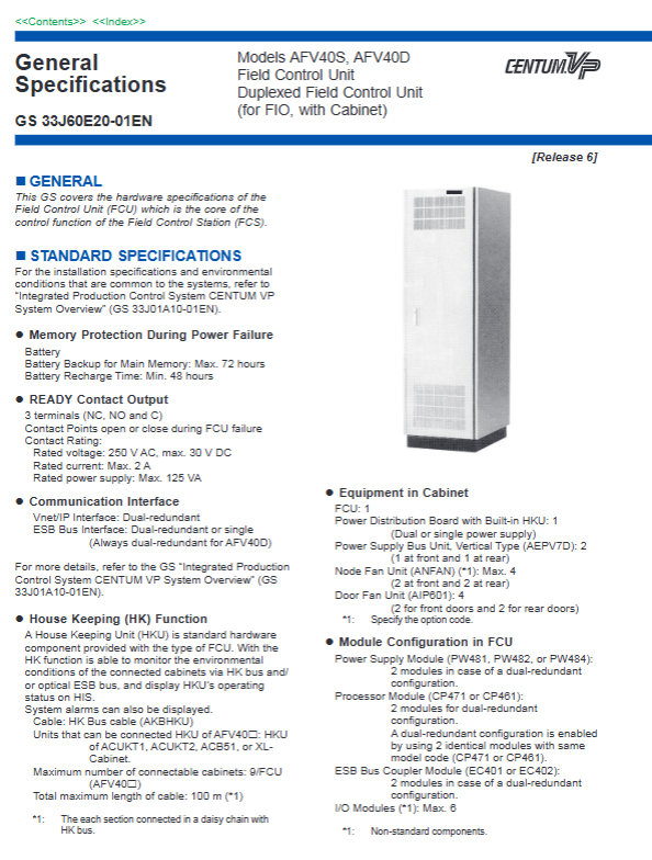
1 power module (PW481/PW482/PW484), 2 optional dual power supplies (redundant configuration) supporting 100-120V AC/220-240V AC/24V DC
1 processor module (CP461/CP471) 2 (redundant of the same model) CP471 needs to be equipped with R6.05 or above control functions
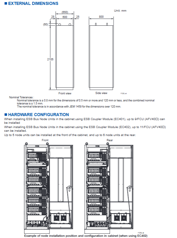
1 ESB bus coupling module (EC401/EC402), optional dual redundancy 2 (EC401/EC402, mandatory dual redundancy) EC401 can connect up to 9 nodes, EC402 can connect up to 11 nodes
Up to 6 I/O modules (non-standard configuration) must comply with the FIO system installation restrictions
2. Built in components of the cabinet
Basic components: 1 FCU, 1 power distribution board with HKU, 2 vertical power bus units (1 front and 1 rear)
Cooling components: 4 door fans (2 for each front and rear door), node fans (ANFAN, configured according to the number of units)
Monitoring component: HKU (House Keeping Unit), standard configuration, supports cabinet environment monitoring
3. Communication interface specifications
Core characteristics of interface type redundancy configuration
Vnet/IP interface dual redundancy (AFV40S selectable power supply, AFV40D forced dual power supply) system control network, redundant switching ensures stable communication
ESB bus interface AFV40S: single/dual redundancy; AFV40D: Mandatory dual redundant connection node unit, EC401 supports bus topology, EC402 supports upper and lower connection nodes
The HK bus interface is connected to the external cabinet HKU via a single channel, with AKBHKU cable and a total length of ≤ 100m
READY contact output 3 terminal (NC/NO/C) fault, contact on/off, rated 250V AC/30V DC, maximum 2A/125VA
Key parameters and physical characteristics
1. Electrical parameters
Parameter specifications
Power supply voltage 100-120V AC (50/60Hz), 220-240V AC (50/60Hz), 24V DC
Maximum power consumption 100-120V AC: 2500VA; 220-240V AC:2860VA; 24V DC:71A
Power down protection: Main memory battery backup takes up to 72 hours and charging takes at least 48 hours
Protection level IP20
2. Physical characteristics
Parameter specifications
External dimensions (mm) Height 2105 x Width 800 x Depth 600 (including 25mm front and rear protrusions)
Weight approximately 240kg (excluding nodes); About 360kg (fully equipped with 11 nodes)
Paint color subject: Frost white (Munsell 2.5Y 8.4/1.2); Channel Base: Spring Black (Munsell 3.3PB2.5/0.5)
Grounding terminal M8 screw terminal connection
Power connection M6 screw terminal connection, supports dual power supply system
Installation restrictions and connection capabilities
1. Node unit connection restrictions
Limit type specifications
Maximum number of connected nodes 13/FCU (ANB10 /ANB11 )
The maximum number of installed units in the cabinet is 11 (ANB10 node unit+ANT10U optical ESB relay unit)
There are a maximum of 5 installation positions in the front and 6 installation positions in the rear of the cabinet
Installation sequence: Install the ANB10 node unit first, and then install the ANT10U relay unit
The optical ESB node connection requires the use of ANT401/ANT411 optical relay modules, with a maximum transmission distance of 50km
2. Fan configuration rules
Number of required node fans (ANFAN) for the total number of units in the cabinet (ANB10 +ANT10U)
0-4 of 1 (option code/1-FAN)
5-9 of 2 (Option Code/2-FAN)
10 of 3 (option code/3-FAN)
11 of 4 (option code/4-FAN)
3. Cable and topology limitations
ESB bus cable: Use YCB301 dedicated cable, pre installed in the cabinet, additional connection is required between ANB10 and ANT10U
HK bus: AKBHKU cable is used to connect external cabinets, with a total length of ≤ 100m (daisy chain connection)
Optical ESB bus: supports chain/star topology and requires the use of ANT401/ANT411 relay modules
Model code and options
1. Basic model and core suffix
Product Model Core Suffix Description Key Configuration
AFV40S (single redundancy) - A/- S (processor type); 3/4 (Vnet/IP and power supply); 1-4 (ESB bus); 1/2/4 (power type) selectable/dual redundant ESB bus, single/dual power supply
AFV40D (dual redundancy) - A/- S (processor type); 4 (Vnet/IP and power supply); 2/4 (ESB bus); 1/2 (power type) mandatory dual redundancy Vnet/IP and ESB bus
2. Main option codes
Option code function description associated model
/ - S1F single ESB bus+single power node unit ANB10S-3 5
/- D2F dual redundant ESB bus+dual power node unit ANB10D-4 5
/ - T2A dual power optical ESB relay unit ANT10U-4 5
/ - FAN node fans (configured by quantity) ANFAN
/CH Channel Base with Cable Hole (300 × 40mm)-
/CE with CE/RCM/AAC/KC certification-
/ATDOC Explosion proof Manual (ATEX Directive Adaptation)-
Software and accessory requirements
Software requirements: A separate software license is required. We recommend VP6F1700 control function software and VP6F3100 Project I/O license
SEM functional requirements: The use of event sequence manager requires specific hardware conditions, refer to GS 33J30D10-01EN
Standard accessories: 2 door fan filters (Part No.T9070CB)
Related products: Cabinet Connection Kit (Model AKT211), Cabinet Side Panel (ACB2P, requires paired configuration)
Key issues
Question 1: What is the core difference between AFV40S and AFV40D? How to select based on project redundancy requirements?
answer
Core Differences:
Redundancy configuration: AFV40S is single redundancy (optional dual redundancy for processor/power/ESB bus), AFV40D is full dual redundancy (mandatory dual redundancy for processor/power/Vnet/IP/ESB bus);
Suffix restrictions: AFV40D only supports dual redundancy related suffixes (such as ESB bus with only 2/4 options), while AFV40S supports single/dual redundancy suffixes;
Node Unit: AFV40S supports single/dual power node units, while AFV40D only supports dual redundant ESB+dual power node units (ANB10D-4 5).
Selection principle:
High reliability requirements (such as critical process control): Choose AFV40D, fully redundant configuration to avoid single point of failure;
Cost sensitive and non critical scenarios: Choose AFV40S and configure single/dual redundant ESB buses and power supplies as needed;
Number of nodes ≤ 9: AFV40S with EC401; Number of nodes 10-11: AFV40S with EC402, AFV40D with EC402.
Question 2: What are the key rules for unit installation and fan configuration in the AFV40 cabinet? How to avoid installation violations?
answer
Unit installation rules:
Quantity limit: A maximum of 11 units (ANB10 +ANT10U) can be installed in the cabinet, with ≤ 5 units in the front and ≤ 6 units in the rear;
Installation sequence: ANB10 node unit must be installed first, followed by ANT10U optical relay unit;
Cable connection: The ESB bus cable (YCB301) inside the cabinet has been pre installed, and manual connection is required between ANB10 and ANT10U.
Fan configuration rules:
The number of node fans (ANFAN) is configured according to the total number of units (0-4 → 1, 5-9 → 2, 10 → 3, 11 → 4);
Door fans are standard configuration (4 units), no additional selection is required.
Avoid violations:
Install strictly in the order of "ANB10 priority", without reversing unit types;
Accurately select fan option codes based on the total number of units, without omission or excessive configuration;
The optical ESB node needs to be connected through the ANT401/ANT411 relay module, not directly connected to the FCU.
Question 3: What are the communication interface and power configuration options for AFV40? How to adapt to different on-site power supply conditions?
answer
Communication interface selection:
Vnet/IP interface: dual redundant configuration (AFV40S can provide a single power supply, AFV40D requires dual power supply), used for system control network;
ESB bus interface: AFV40S can be selected as a single menu (EC401/EC402 × 1) or dual redundancy (EC401/EC402 × 2), AFV40D is mandatory dual redundancy, used to connect node units;
HK bus interface: single channel, used to connect external cabinet HKU, total length ≤ 100m.
Power configuration selection:
Power supply type: Supports 100-120V AC (50/60Hz), 220-240V AC (50/60Hz), 24V DC, specified by suffix code;
Power redundancy: AFV40S can provide single/dual power supply, while AFV40D requires dual power supply.
On site adaptation plan:
Conventional industrial power supply (220-240V AC): choose suffix "2", AFV40S can be a single power supply (suffix "3") or a dual power supply (suffix "4");
Low voltage scenario (24V DC): Select suffix "4" and confirm that the on-site DC power supply capacity is ≥ 71A;
Cross border project: Select option code "/CE" to obtain CE/RCM/ECC/KC multi certification adaptation;
Explosion proof scenario: Select option code "/ATDOC" to obtain the ATEX Directive Adaptation Manual.
- OMRON
- ABB
- General Electric
- EMERSON
- Honeywell
- HIMA
- ALSTOM
- Rolls-Royce
- MOTOROLA
- Rockwell
- Siemens
- Woodward
- YOKOGAWA
- FOXBORO
- KOLLMORGEN
- MOOG
- KB
- YAMAHA
- BENDER
- TEKTRONIX
- Westinghouse
- AMAT
- AB
- XYCOM
- Yaskawa
- B&R
- Schneider
- KONGSBERG
- NI
- WATLOW
- ProSoft
- SEW
- ADVANCED
- Reliance
- TRICONEX
- METSO
- MAN
- Advantest
- STUDER
- DANAHER MOTION
- Bently
- Galil
- EATON
- MOLEX
- DEIF
- B&W
- ZYGO
- Aerotech
- DANFOSS
- Beijer
- Moxa
- Rexroth
- Johnson
- WAGO
- TOSHIBA
- BMCM
- SMC
- HITACHI
- HIRSCHMANN
- Application field
- XP POWER
- CTI
- TRICON
- STOBER
- Thinklogical
- Horner Automation
- Meggitt
- Fanuc
- Baldor
- SHINKAWA
- Other Brands
- UniOP
- KUKA
- Iba
- Beckhoff
-
 Basler DECS-200-2L Digital Excitation Control
 -
 Basler BE1-47N Voltage Phase Sequence Relay
 -
 Basler AEC63-7 Analog Excitation Controller 220-277V
 -
 Basler BE1-50/51B-107 Overcurrent Relay
 -
 Basler Electric BE1‑32R BE1‑E1P‑BON0F Protective Relay
 -
 Basler BE1-25 Solid State Time Overcurrent Relay M1EA6PA5S1F
 -
 Basler MVC 232 Manual Voltage Control Module 90 37000 103 60VAC 55VDC
 -
 Basler RAL6144-16GM Racer GigE Line Scan Camera
 -
 Basler SSR 63-12 Static Voltage Regulator
 -
 Basler BE1-51A Overcurrent Relay
 -
 Basler BE1-87T Solid State Protective Relay
 -
 Basler SR4A2B01B3A Static Voltage Regulator
 -
 Basler SSR 32-12 Static Voltage Regulator
 -
 Basler TRR00696 Transformer 1KVA 115V
 -
 Basler DECS-100-B15 AVR Replacement
 -
Basler BE1-27 Under-Voltage Relay
-
 Basler ACA2000-50GM Interface Module
 -
 Basler AEC63-7 Analog Excitation Controller
 -
 Basler PRS 250 Veri-Sync Relay
 -
 Basler SR4A-2B15B3A Static Voltage Regulator
 -
Basler BE1-32R Power Relay
-
Basler SR8A-2B06B3E Static Voltage Regulator
-
Basler BE1-81 O/U Frequency Relay
-
 Basler BE1-51A-K2E-W6M-B1N0F Overcurrent Relay
 -
Basler BE1-851 Overcurrent Relay G3A1S1 – 48-125V AC/DC
-
 Basler BEI-51 Overcurrent Relay – NSN 5945-01-293-2363
 -
Basler Electric L301KC Protective Relay – L301KC
-
 Basler DECS-100-B15 Automatic Voltage Regulator – Generator AVR
 -
 Basler SR4A-2B15B3A Static Voltage Regulator – SR4A2B15B3A
 -
 Basler UF 312 Under Frequency Protective Module – 9094700100
 -
Basler Electric MVC 232 Manual Control Module – 60VAC 55VDC 20A
-
Basler PRS 250 Veri-Sync Relay – Generator Synchronizing Relay
-
 Basler DECS-100-A05 Digital Regulator Review
 -
 Basler AEM-2020 Analog Expansion Module Specs
 -
 Basler DECS-100-B15 Digital Excitation Specs
 -
Basler Electric 9125600106 Regulator Component
-
Basler BE1-51A-K1E-W6M-B1N0F Overcurrent Relay
-
 Basler MVC-301 MVC 300 Excitation Controller
 -
 Basler SSR 32-12 Static Voltage Regulator
 -
 Basler 9-2849-00-101 Control Module
 -
Basler BE1-51A Overcurrent Relay
-
 Basler BE1-51/27R Overcurrent Relay
 -
 Basler BE1-51 Overcurrent Relay
 -
 Basler SR8A-2B15B3A Static Voltage Regulator
 -
 Basler BE32965001 Transformer and Timer Board
 -
 Basler 9174700100 EL200-7 Excitation Limiter
 -
 Basler BE2000E AVR Voltage Regulator
 -
Basler BE1-87G Differential Relay
-
 Basler BE21834001 Generator Control Module
 -
Basler DECS-100-B15 AVR
-
 Basler D90 96801 100 PCB Card
 -
 Basler XR2002F Voltage Regulator (110 VAC, 48-480 Hz)
 -
 Basler SR8A-2B14B3A Regulator
 -
 Basler 9561500100 Module
 -
 Basler DECS-400 BE1-11 System
 -
 Basler DECS-100-B15 Excitation Control
 -
 Basler SCP 210 Frequency Controller
 -
Basler SR4A-2B15B3A Static Voltage Regulator
-
Basler BE1-32R Power Relay
-
 Basler PIA2400-17GM Power Interface Adapter
 -
 Basler MVC 232 Manual Voltage Control Module
 -
 Basler SSR 32-12 Static Voltage Regulator
 -
Basler 5MW AVR Generator Voltage Regulator
-
 Basler VR63-4B Voltage Regulator
 -
Basler DECS-100-A05 AVR for Engine Generator
-
Basler DECS-100-B15 Automatic Voltage Regulator
-
Basler BE1-32R Directional Power Relay
-
Basler BE1-87B Differential Relay
-
 Basler UFOV 260A Protective Module
 -
 Basler 9-2614-02-100 PCB Rev M
 -
Basler DECS-100-B15 Digital AVR
-
 Basler 9284900103 PS DECS-400N
 -
 Basler D4N3H1U Intertie Protection
 -
 Basler DECS-100-B15 A15 AVR
 -
 Basler KR4F Voltage Regulator
 -
 Basler BE26434 T14 Transformer
 -
 Basler SR8A-2B15B3A Regulator
 -
 Westinghouse 774B472A12 AR Relay
 -
Basler DECS-100-B15 AVR
-
Basler XR2002F Regulator 110V
-
Basler SR125-E Static Regulator
-
Basler SSR 125-12 Regulator
-
Basler MOC2599 Motor Pot
-
 Basler BE1-DFPR Feeder Relay
 -
 Basler CBS 305 Current Boost
 -
Basler BE1-25 AutoSync
-
Basler MVC 300 Voltage Control
-
 Basler BE3-25A AutoSync
 -
 Basler KR7FF Static Regulator
 -
Basler 90-49000-100 Regulator
-
 Basler 880 kVA Dry Type Transformer Specs
 -
Basler Electric BE1-25 Sync-Check Relay Specs
-
 Basler SSR 125-12 Voltage Regulator Specs
 -
 Basler Electric BE1-851 Overcurrent Relay Review
 -
Basler Electric 149D930G02 Control Sub-Assembly
-
 Basler Electric BE1-81O/UT Frequency Relay Specs
 -
 Basler Electric BE1-51/27C Overcurrent Relay
 -
 Basler Electric 149D956G02 Industrial Component
 -
Basler Electric BE1-51A Overcurrent Relay Specs
-
 Basler Electric BE1-40Q Loss of Excitation Relay
 -
Basler DECS-200 Excitation Control System
-
 Basler DECS-200 Voltage Regulator 56-277V AC / 125V DC
 -
Basler BE1-87T Transformer Differential Relay
-
 Basler RDP-110-S1 Protection Relay
 -
 Basler BE1-700V Digital Protective Relay
 -
 Basler BE1-951 Overcurrent Protection System
 -
 Basler DECS-300 Digital Excitation Control
 -
 Basler DECS-200 Digital Excitation Control
 -
 Basler DECS-200-1C Excitation Control System
 -
Basler DECS-200-1L Digital Excitation Control
-
 Basler Electric BE1-GPS Generator Protection System
 -
Basler Electric DECS-200-1C Digital Excitation Controller
-
 Basler Electric DECS125-15 Excitation Control with Power Module
 -
Basler Electric BE1-87G Differential Relay
-
 Basler Electric BE1-11 Protection System I5A3M2P2N0EA00
 -
Basler Electric DECS-200-1C Excitation Control System
-
Basler Electric BE1-11g Generator Protection Relay
-
Basler Electric DECS 125-15-B2C1 V2.0.9 Excitation Control
-
Basler Electric BE1-81O/UT3ED1JA7N2F Frequency Relay
-
Basler Electric BE1-81O/UT3EE1YB7N1F Frequency Relay
-
 Basler Electric DECS-200-1L Digital Excitation Control System
 -
Basler DECS125-15-B2C1 Excitation Control
-
 Basler 9507900205 SSR Retrofit Voltage Regulator
 -
 Basler BE2000E Digital Voltage Regulator
 -
 Basler BE1-GPS Generator Protection System
 -
Basler DECS-250-CN1CN1N Digital Excitation Control
-
 Basler DGC-2020 Genset Controller
 -
Basler BE1-81O UT3ED1LA7N0F Frequency Relay (Variant)


