
YOKOGAWA VP6F1900/1905 Control Function (A2FV70 Dedicated)
YOKOGAWA VP6F1900/1905 Control Function (A2FV70 Dedicated)
GENERAL
VP6F1900 Control Function for Field Control Station (FCS) (for A2FV70) is installed and runs in the following FCS models:
A2FV70S, A2FV70D
Both VP6F1900 Control Function for Field Control Station and VP6F1905 Control Function for FCS
Simulator have the same functional specifications, except that one runs on a real machine and the other runs on a simulator.
This document describes the common contents for both models unless noted otherwise.
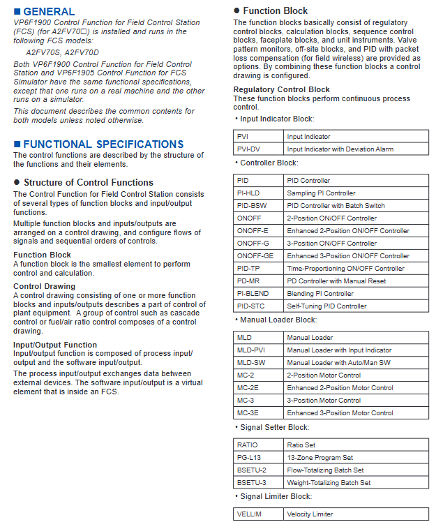
FUNCTIONAL SPECIFICATIONS
The control functions are described by the structure of the functions and their elements.
Structure of Control Functions
The Control Function for Field Control Station consists of several types of function blocks and input/output functions.
Multiple function blocks and inputs/outputs are arranged on a control drawing, and configure flows of signals and sequential orders of controls.
Function Block
A function block is the smallest element to perform control and calculation.
Control Drawing
A control drawing consisting of one or more function blocks and inputs/outputs describes a part of control of plant equipment. A group of control such as cascade control or fuel/air ratio control composes of a control drawing.
Input/Output Function
Input/output function is composed of process input/ output and the software input/output.
The process input/output exchanges data between external devices. The software input/output is a virtual element that is inside an FCS.
Classification and specifications of core functional blocks
1. Basic functional blocks (7 categories)
Functional block type, core usage, representative model and key characteristics
Continuous process control PID (standard PID), PID-STC (self-tuning PID), ONOFF (two position switch control), FF-PID (fieldbus PID), etc
Compute block signal operations and logical processing ADD (addition), SQRT (square root), AND (logical AND), Calcu (general computing), etc
Sequence control block interlocking and batch control ST (sequence table), LC (logic diagram), SIO-11E (enhanced switch instrument), TMF (timer), etc
Panel block multifunctional block unified label display INDST3 (three pointer manual station), BSI (batch status indication), HAS3C (mixed manual station), etc
Unit instrument block, whole unit equipment control, UTAS (analog unit instrument), UTPB-N (non resident 5-key unit instrument), etc
Valve mode monitoring block (optional) Valve switch status monitoring VPM64 (64 points) - VPM512A (512 points with alarm)
Off site Block (optional) Refinery Off site Mixing/Shipping Control FSBSET (batch setting), BLEND (mixing master control)
2. Featured functional blocks (3 types of core extensions)
Functional block type, core characteristics, applicable scenarios
ZWOPID (Wireless PID Compensation) is compatible with wireless field devices and provides PID control for stable process response in wireless communication scenarios when data packets are lost
YS instrument block compatible with YS series controllers/manual stations/total meters YS series instrument integrated control
Enhanced switch instrument block supports 1-2 input/output channels, including single trigger output type complex interlocking logic control
I/O function and communication support
1. Classification of I/O functions
I/O Type Core Function Signal Identification/Support Range
Process I/O on-site device signal interaction simulation I/O ≤ 1760 points, contact I/O ≤ 4096 points
Software I/O FCS internal virtual signal internal switches (% SW: 9999,% GS: 256), message output (6 types of messages including% AN/% PR)
Communication I/O subsystem data exchange% W/% X identification, supports PLC and other subsystem data access, 16 bit data volume ≤ 8000 words
Fieldbus I/O fieldbus device access% Z identification, compatible with FOUNDATION fieldbus devices
2. Subsystem Communication Protocol
Supports 5 types of core communication modules and protocols, requiring corresponding hardware modules:
Serial communication: ALR111/ALR121 modules (N-IO/FIO specific)
Ethernet communication: ALE111 module (N-IO/FIO specific)
FOUNDATION fieldbus communication: ALF111 module (N-IO/FIO specific)
PROFIBUS-DP communication: ALP121 module (N-IO/FIO specific)
PROFINET communication: A2LP131 module (N-IO/FIO specific)
Application capacity and operating parameters
1. Core indicators for three types of capacity configuration
Configuration type: Standard type (C01) Extended type (C02) Large type (C03)
Number of tags (maximum) 18000 18000 18000 18000
Number of functional blocks (maximum) 5500 7000 9000
Simulate I/O points (maximum) 1760 points 1760 points 1760 points
Contact I/O points (maximum) 4096 points 4096 points 4096 points 4096 points
Control the number of drawings 200 (optional 300/400/500) 200 (optional 300/400/500)
1 second trend collection points 1024 points 1024 points 1024 points
2. Scanning cycle and database requirements
Scanning cycle:
Standard scan: 1 second (fixed)
Medium speed scanning: 200ms/500ms (can directly input 50/100/250ms), suitable for analog quantity calculation
High speed scanning: 200ms/500ms (can directly input 50/100/250ms), suitable for sequence control
- OMRON
- ABB
- General Electric
- EMERSON
- Honeywell
- HIMA
- ALSTOM
- Rolls-Royce
- MOTOROLA
- Rockwell
- Siemens
- Woodward
- YOKOGAWA
- FOXBORO
- KOLLMORGEN
- MOOG
- KB
- YAMAHA
- BENDER
- TEKTRONIX
- Westinghouse
- AMAT
- AB
- XYCOM
- Yaskawa
- B&R
- Schneider
- KONGSBERG
- NI
- WATLOW
- ProSoft
- SEW
- ADVANCED
- Reliance
- TRICONEX
- METSO
- MAN
- Advantest
- STUDER
- DANAHER MOTION
- Bently
- Galil
- EATON
- MOLEX
- DEIF
- B&W
- ZYGO
- Aerotech
- DANFOSS
- Beijer
- Moxa
- Rexroth
- Johnson
- WAGO
- TOSHIBA
- BMCM
- SMC
- HITACHI
- HIRSCHMANN
- Application field
- XP POWER
- CTI
- TRICON
- STOBER
- Thinklogical
- Horner Automation
- Meggitt
- Fanuc
- Baldor
- SHINKAWA
- Other Brands
- UniOP
- KUKA
- Iba
- Beckhoff
-
 Basler D90 96801 100 PCB Card
 -
 Basler XR2002F Voltage Regulator (110 VAC, 48-480 Hz)
 -
 Basler SR8A-2B14B3A Regulator
 -
 Basler 9561500100 Module
 -
 Basler DECS-400 BE1-11 System
 -
 Basler DECS-100-B15 Excitation Control
 -
 Basler SCP 210 Frequency Controller
 -
 Basler SR4A-2B15B3A Static Voltage Regulator
 -
 Basler BE1-32R Power Relay
 -
 Basler PIA2400-17GM Power Interface Adapter
 -
 Basler MVC 232 Manual Voltage Control Module
 -
 Basler SSR 32-12 Static Voltage Regulator
 -
 Basler 5MW AVR Generator Voltage Regulator
 -
 Basler VR63-4B Voltage Regulator
 -
 Basler DECS-100-A05 AVR for Engine Generator
 -
 Basler DECS-100-B15 Automatic Voltage Regulator
 -
 Basler BE1-32R Directional Power Relay
 -
 Basler BE1-87B Differential Relay
 -
 Basler UFOV 260A Protective Module
 -
 Basler 9-2614-02-100 PCB Rev M
 -
Basler DECS-100-B15 Digital AVR
-
 Basler 9284900103 PS DECS-400N
 -
 Basler D4N3H1U Intertie Protection
 -
 Basler DECS-100-B15 A15 AVR
 -
 Basler KR4F Voltage Regulator
 -
 Basler BE26434 T14 Transformer
 -
 Basler SR8A-2B15B3A Regulator
 -
 Westinghouse 774B472A12 AR Relay
 -
Basler DECS-100-B15 AVR
-
Basler XR2002F Regulator 110V
-
Basler SR125-E Static Regulator
-
 Basler SSR 125-12 Regulator
 -
 Basler MOC2599 Motor Pot
 -
 Basler BE1-DFPR Feeder Relay
 -
 Basler CBS 305 Current Boost
 -
 Basler BE1-25 AutoSync
 -
 Basler MVC 300 Voltage Control
 -
 Basler BE3-25A AutoSync
 -
 Basler KR7FF Static Regulator
 -
 Basler 90-49000-100 Regulator
 -
 Basler 880 kVA Dry Type Transformer Specs
 -
 Basler Electric BE1-25 Sync-Check Relay Specs
 -
 Basler SSR 125-12 Voltage Regulator Specs
 -
 Basler Electric BE1-851 Overcurrent Relay Review
 -
Basler Electric 149D930G02 Control Sub-Assembly
-
 Basler Electric BE1-81O/UT Frequency Relay Specs
 -
 Basler Electric BE1-51/27C Overcurrent Relay
 -
 Basler Electric 149D956G02 Industrial Component
 -
Basler Electric BE1-51A Overcurrent Relay Specs
-
 Basler Electric BE1-40Q Loss of Excitation Relay
 -
 Basler DECS-200 Excitation Control System
 -
 Basler DECS-200 Voltage Regulator 56-277V AC / 125V DC
 -
Basler BE1-87T Transformer Differential Relay
-
 Basler RDP-110-S1 Protection Relay
 -
 Basler BE1-700V Digital Protective Relay
 -
 Basler BE1-951 Overcurrent Protection System
 -
 Basler DECS-300 Digital Excitation Control
 -
 Basler DECS-200 Digital Excitation Control
 -
 Basler DECS-200-1C Excitation Control System
 -
Basler DECS-200-1L Digital Excitation Control
-
 Basler Electric BE1-GPS Generator Protection System
 -
Basler Electric DECS-200-1C Digital Excitation Controller
-
 Basler Electric DECS125-15 Excitation Control with Power Module
 -
 Basler Electric BE1-87G Differential Relay
 -
 Basler Electric BE1-11 Protection System I5A3M2P2N0EA00
 -
Basler Electric DECS-200-1C Excitation Control System
-
Basler Electric BE1-11g Generator Protection Relay
-
Basler Electric DECS 125-15-B2C1 V2.0.9 Excitation Control
-
 Basler Electric BE1-81O/UT3ED1JA7N2F Frequency Relay
 -
Basler Electric BE1-81O/UT3EE1YB7N1F Frequency Relay
-
 Basler Electric DECS-200-1L Digital Excitation Control System
 -
Basler DECS125-15-B2C1 Excitation Control
-
 Basler 9507900205 SSR Retrofit Voltage Regulator
 -
 Basler BE2000E Digital Voltage Regulator
 -
 Basler BE1-GPS Generator Protection System
 -
Basler DECS-250-CN1CN1N Digital Excitation Control
-
 Basler DGC-2020 Genset Controller
 -
 Basler BE1-81O UT3ED1LA7N0F Frequency Relay (Variant)
 -
 Basler BE1-81O UT3EE1YA9S0F Frequency Relay (Variant)
 -
Basler BE1-81O Over/Under Frequency Relay
-
Basler DECS125-15 Digital Excitation Control
-
Basler Electric BE1-951 Overcurrent Protection System
-
 Basler Electric BE1-700V Digital Protective Relay
 -
 Basler Electric APR63-5 Automatic Voltage Regulator
 -
Basler Electric BE1-851 Overcurrent Protection System
-
Basler Electric DECS-250-LN1SN1N Excitation Control
-
 Basler Electric BE1-87T Transformer Differential Relay
 -
Basler Electric DECS-200-1L Excitation Control System
-
 Basler Electric 9310300100 DECS-300 Excitation Control
 -
 Basler Electric SSE-N 125-4.5KW Shunt Exciter Regulator
 -
 Basler Electric DGC-2020HD-5NS1DNSBA Genset Controller
 -
Basler Electric BE1-81-O/UT3EE1JB7N1F Frequency Relay
-
Basler Electric BE1-81T1EE1WA0N1F Frequency Relay
-
 Basler Electric BE1-25M1EA6PN5R1F Sync-Check Relay
 -
 Basler Electric BE1-GPS Generator Protection System
 -
Basler Electric DECS-250-LN1SN1N Excitation Control Rev V
-
 Basler Electric DECS-250-CN2CN1N Excitation Control
 -
Basler Electric BE1-50/51B-207 Overcurrent Relay
-
Basler Electric DECS-300-C0N0 Excitation Control System
-
Basler Electric DECS-200 Digital Excitation Control System
-
Basler Electric DECS-250-LN1CN1N Excitation Unit
-
Basler Electric DECS-250 LN2SA1D Excitation Unit Specs
-
Basler Electric BE1-87T Transformer Relay Review
-
Basler Electric BE1-11 Protection System
-
Basler Electric BE1-GPS100-E4N1H1N Protection System
-
 Allen-Bradley 442G-MABH-R Safety Module
 -
 Beckhoff CX1030-0111 PLC Assembly Profile
 -
 FANUC IC693CPU364 PLC Module
 -
 Orange Denmark Type 200816 220 PLC Specs
 -
 OMRON C200H-SNT31 Sysmac PLC Module
 -
 Allen Bradley 20AB022A3AYNANC0 PowerFlex 70
 -
 OMRON C200HW-PCU01 Position Control Unit
 -
 ABB AO845A-eA Analog Output Module
 -
 OMRON CJ1M-CPU22 CPU Unit
 -
 Allen Bradley 100-E265ED11 Contactor
 -
 Honeywell 51304511-100 Interface Module
 -
 SOLEXY BXF3S0101N0018 Gateway Module
 -
 OMRON CJ2H-CPU65 CPU Unit
 -
 Automation Direct GS2-45P0 AC Drive
 -
 M68-2000 2-Axis Motion CNC Controller
 -
 OMRON CJ1M-CPU11 V3.0 PLC CPU Unit
 -
 OMRON CJ1W-NC413 4-Axis Positioning Controller
 -
 OMRON 3G2A3-PRO16 Programming Console HMI
 -
 Siemens 3VT8440-2AA04-2GA2 Molded Case Circuit Breaker
 -
 Siemens 3RT5045 Contactor Series
 -
 OMRON C200HS-CPU01-E SYSMAC PLC Controller
 -
 OMRON C500-NC103-E Positioning Control Unit
 -
 OMRON CJ1W-TC001 Temperature Control Unit


