
YOKOGAWA YS100 series instrument
YS170 (Programmable Controller) SLPC supports PV/SV/MV read and write, program control parameter adjustment, and alarm status monitoring
YS135 (SV setting automatic/manual station) SMST-111 supports PV monitoring, SV setting, and high/low limit alarm configuration
YS136 (MV setting automatic/manual station) SMST-121 supports PV monitoring, MV setting, and upper and lower limit configuration of operating variables
Installation and wiring specifications
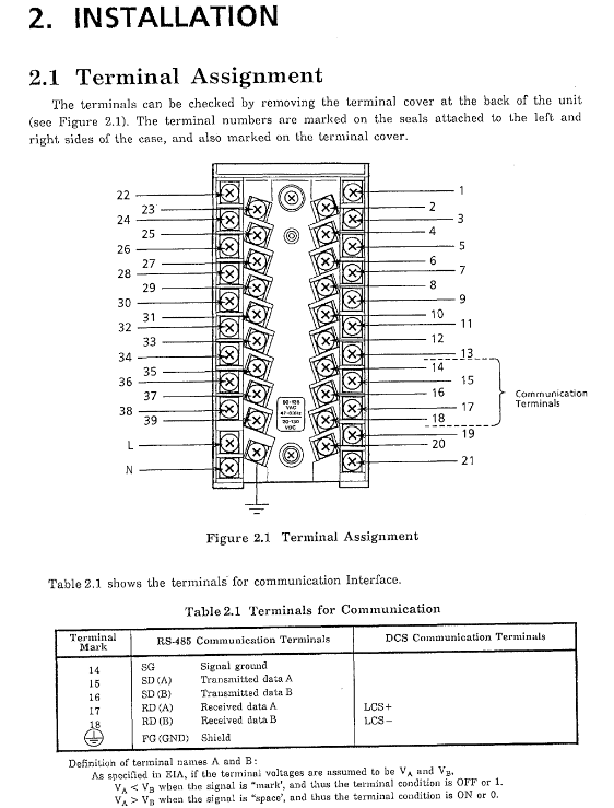
(1) Terminal allocation
The communication terminal of YS100 series instruments is located on the back of the equipment, and can be viewed after removing the terminal cover. The terminal number is marked on the sealing parts and terminal cover on both sides of the chassis. The core communication terminals are assigned as follows:
Terminal Number RS-485 Communication Function DCS-LCS Communication Function Remarks
14 Signal Ground (SG) LCS+, LCS - dual function terminal, switch usage according to communication options
15 Send Data A (SD (A)) - Used only for RS-485 communication
16 Send Data B (SD (B)) - Used only for RS-485 communication
17 Receive Data A (RD (A)) - Used only for RS-485 communication
18 Receive Data B (RD (B)) - Used only for RS-485 communication
FG (GND) shielding layer grounding shielding layer grounding forced grounding, used for anti-interference
Note: The voltage definition of terminals A and B follows the EIA standard: when the signal is "mark" and VA<VB, the corresponding terminal status is OFF or 1; When the signal is "space" and VA>VB, the corresponding terminal status is ON or 0.
(2) RS-485 communication wiring
1. Four wire wiring system
Applicable scenarios: Bidirectional communication scenarios that require simultaneous sending and receiving, with higher communication stability;
Wiring requirements: Use 4-core shielded twisted pair cables to connect SD (A), SD (B), RD (A), and RD (B) respectively. The signal ground (SG) and shielding layer (FG) should be grounded together to avoid common mode interference;
Terminal resistance: Connect 120 Ω terminal resistors between SD (A) - SD (B) and RD (A) - RD (B) on the monitoring computer side and the farthest instrument side, respectively.
2. Two wire wiring system
Applicable scenarios: scenarios with low communication speed requirements and sensitive wiring costs;
Wiring requirements: Use 2-core shielded twisted pair, short-circuit SD (A) and RD (A), short-circuit SD (B) and RD (B), and connect them to the bus. Signal ground and shielding layer ground;
Terminal resistor: Connect a 120 Ω terminal resistor between the short circuited terminals at both ends of the bus.
3. Wiring precautions
Avoid parallel laying with power cables. If crossing is necessary, maintain a 90 ° vertical crossing to reduce electromagnetic interference;
The shielding layer needs to be grounded at one end (recommended to be grounded on the monitoring computer side) to avoid the formation of a grounding loop at both ends;
The cable length cannot exceed 1200m, and if it exceeds this limit, a signal amplifier (compatible with RS-485 protocol) must be used;
When multiple instruments are connected, a bus topology structure is used, and star connections are prohibited to avoid signal reflection.
(3) DCS-LCS communication cabling
1. Core wiring structure
Link composition: DCS field control unit (such as MFCU) → LCS communication card → TE08 terminal block → YS100 instrument, connected to SCCD twisted pair cable through KS4 cable;
Wiring distance: The maximum length of a single section of KS4 cable is 100m. The length of the SCCD twisted pair between the TE08 terminal block and the instrument should be adjusted according to the site layout, and the total attenuation should be controlled;
Shielding requirement: The shielding layer of all communication cables must be connected to the shielding terminal (S) of TE08 terminal block to achieve unified grounding.
2. YS100 and TE08 terminal block wiring
Wiring method: Each YS100 instrument is connected to the LCS+and LCS - terminals of the TE08 terminal block through SCCD twisted pair cables. Terminal 17 corresponds to LCS+, and terminal 18 corresponds to LCS -;
Connection restriction: A single TE08 terminal block can connect up to 8 YS100 instruments, and multiple instruments can be connected in parallel on the same LCS+or LCS - bus.
Communication parameter configuration
(1) Configure entrance and basic parameters
1. Configuration method
The communication parameters are set through the engineering panel group (CONFIG1 menu) on the instrument front-end panel, and only the enable/disable of the terminal resistor needs to be operated through the JP1 jumper on the RS-485 communication board (hardware configuration).
2. Core configuration parameters (CONFIG1 menu)
Line number display item function description default value optional range remark
1 SET configuration enable/disable INHB (disable) INHB, ENBL (enable) must be set to ENBL to modify other parameters
5 COMM communication function display -485 (RS-485), LCS (DCS-LCS) automatically recognizes installed communication options without manual setting
When COMWR communication is enabled with ENBL (allowed) and INHB (prohibited), instrument parameters cannot be modified through communication
- OMRON
- ABB
- General Electric
- EMERSON
- Honeywell
- HIMA
- ALSTOM
- Rolls-Royce
- MOTOROLA
- Rockwell
- Siemens
- Woodward
- YOKOGAWA
- FOXBORO
- KOLLMORGEN
- MOOG
- KB
- YAMAHA
- BENDER
- TEKTRONIX
- Westinghouse
- AMAT
- AB
- XYCOM
- Yaskawa
- B&R
- Schneider
- KONGSBERG
- NI
- WATLOW
- ProSoft
- SEW
- ADVANCED
- Reliance
- TRICONEX
- METSO
- MAN
- Advantest
- STUDER
- DANAHER MOTION
- Bently
- Galil
- EATON
- MOLEX
- DEIF
- B&W
- ZYGO
- Aerotech
- DANFOSS
- Beijer
- Moxa
- Rexroth
- Johnson
- WAGO
- TOSHIBA
- BMCM
- SMC
- HITACHI
- HIRSCHMANN
- Application field
- XP POWER
- CTI
- TRICON
- STOBER
- Thinklogical
- Horner Automation
- Meggitt
- Fanuc
- Baldor
- SHINKAWA
- Other Brands
- UniOP
- KUKA
- Iba
- Beckhoff
-
 Basler D90 96801 100 PCB Card
 -
 Basler XR2002F Voltage Regulator (110 VAC, 48-480 Hz)
 -
 Basler SR8A-2B14B3A Regulator
 -
 Basler 9561500100 Module
 -
 Basler DECS-400 BE1-11 System
 -
 Basler DECS-100-B15 Excitation Control
 -
 Basler SCP 210 Frequency Controller
 -
 Basler SR4A-2B15B3A Static Voltage Regulator
 -
 Basler BE1-32R Power Relay
 -
 Basler PIA2400-17GM Power Interface Adapter
 -
 Basler MVC 232 Manual Voltage Control Module
 -
 Basler SSR 32-12 Static Voltage Regulator
 -
 Basler 5MW AVR Generator Voltage Regulator
 -
 Basler VR63-4B Voltage Regulator
 -
 Basler DECS-100-A05 AVR for Engine Generator
 -
 Basler DECS-100-B15 Automatic Voltage Regulator
 -
 Basler BE1-32R Directional Power Relay
 -
 Basler BE1-87B Differential Relay
 -
 Basler UFOV 260A Protective Module
 -
 Basler 9-2614-02-100 PCB Rev M
 -
Basler DECS-100-B15 Digital AVR
-
 Basler 9284900103 PS DECS-400N
 -
 Basler D4N3H1U Intertie Protection
 -
 Basler DECS-100-B15 A15 AVR
 -
 Basler KR4F Voltage Regulator
 -
 Basler BE26434 T14 Transformer
 -
 Basler SR8A-2B15B3A Regulator
 -
 Westinghouse 774B472A12 AR Relay
 -
Basler DECS-100-B15 AVR
-
Basler XR2002F Regulator 110V
-
Basler SR125-E Static Regulator
-
 Basler SSR 125-12 Regulator
 -
 Basler MOC2599 Motor Pot
 -
 Basler BE1-DFPR Feeder Relay
 -
 Basler CBS 305 Current Boost
 -
 Basler BE1-25 AutoSync
 -
 Basler MVC 300 Voltage Control
 -
 Basler BE3-25A AutoSync
 -
 Basler KR7FF Static Regulator
 -
 Basler 90-49000-100 Regulator
 -
 Basler 880 kVA Dry Type Transformer Specs
 -
 Basler Electric BE1-25 Sync-Check Relay Specs
 -
 Basler SSR 125-12 Voltage Regulator Specs
 -
 Basler Electric BE1-851 Overcurrent Relay Review
 -
Basler Electric 149D930G02 Control Sub-Assembly
-
 Basler Electric BE1-81O/UT Frequency Relay Specs
 -
 Basler Electric BE1-51/27C Overcurrent Relay
 -
 Basler Electric 149D956G02 Industrial Component
 -
Basler Electric BE1-51A Overcurrent Relay Specs
-
 Basler Electric BE1-40Q Loss of Excitation Relay
 -
 Basler DECS-200 Excitation Control System
 -
 Basler DECS-200 Voltage Regulator 56-277V AC / 125V DC
 -
Basler BE1-87T Transformer Differential Relay
-
 Basler RDP-110-S1 Protection Relay
 -
 Basler BE1-700V Digital Protective Relay
 -
 Basler BE1-951 Overcurrent Protection System
 -
 Basler DECS-300 Digital Excitation Control
 -
 Basler DECS-200 Digital Excitation Control
 -
 Basler DECS-200-1C Excitation Control System
 -
Basler DECS-200-1L Digital Excitation Control
-
 Basler Electric BE1-GPS Generator Protection System
 -
Basler Electric DECS-200-1C Digital Excitation Controller
-
 Basler Electric DECS125-15 Excitation Control with Power Module
 -
 Basler Electric BE1-87G Differential Relay
 -
 Basler Electric BE1-11 Protection System I5A3M2P2N0EA00
 -
Basler Electric DECS-200-1C Excitation Control System
-
Basler Electric BE1-11g Generator Protection Relay
-
Basler Electric DECS 125-15-B2C1 V2.0.9 Excitation Control
-
 Basler Electric BE1-81O/UT3ED1JA7N2F Frequency Relay
 -
Basler Electric BE1-81O/UT3EE1YB7N1F Frequency Relay
-
 Basler Electric DECS-200-1L Digital Excitation Control System
 -
Basler DECS125-15-B2C1 Excitation Control
-
 Basler 9507900205 SSR Retrofit Voltage Regulator
 -
 Basler BE2000E Digital Voltage Regulator
 -
 Basler BE1-GPS Generator Protection System
 -
Basler DECS-250-CN1CN1N Digital Excitation Control
-
 Basler DGC-2020 Genset Controller
 -
 Basler BE1-81O UT3ED1LA7N0F Frequency Relay (Variant)
 -
 Basler BE1-81O UT3EE1YA9S0F Frequency Relay (Variant)
 -
Basler BE1-81O Over/Under Frequency Relay
-
Basler DECS125-15 Digital Excitation Control
-
Basler Electric BE1-951 Overcurrent Protection System
-
 Basler Electric BE1-700V Digital Protective Relay
 -
 Basler Electric APR63-5 Automatic Voltage Regulator
 -
Basler Electric BE1-851 Overcurrent Protection System
-
Basler Electric DECS-250-LN1SN1N Excitation Control
-
 Basler Electric BE1-87T Transformer Differential Relay
 -
Basler Electric DECS-200-1L Excitation Control System
-
 Basler Electric 9310300100 DECS-300 Excitation Control
 -
 Basler Electric SSE-N 125-4.5KW Shunt Exciter Regulator
 -
 Basler Electric DGC-2020HD-5NS1DNSBA Genset Controller
 -
Basler Electric BE1-81-O/UT3EE1JB7N1F Frequency Relay
-
Basler Electric BE1-81T1EE1WA0N1F Frequency Relay
-
 Basler Electric BE1-25M1EA6PN5R1F Sync-Check Relay
 -
 Basler Electric BE1-GPS Generator Protection System
 -
Basler Electric DECS-250-LN1SN1N Excitation Control Rev V
-
 Basler Electric DECS-250-CN2CN1N Excitation Control
 -
Basler Electric BE1-50/51B-207 Overcurrent Relay
-
Basler Electric DECS-300-C0N0 Excitation Control System
-
Basler Electric DECS-200 Digital Excitation Control System
-
Basler Electric DECS-250-LN1CN1N Excitation Unit
-
Basler Electric DECS-250 LN2SA1D Excitation Unit Specs
-
Basler Electric BE1-87T Transformer Relay Review
-
Basler Electric BE1-11 Protection System
-
Basler Electric BE1-GPS100-E4N1H1N Protection System
-
 Allen-Bradley 442G-MABH-R Safety Module
 -
 Beckhoff CX1030-0111 PLC Assembly Profile
 -
 FANUC IC693CPU364 PLC Module
 -
 Orange Denmark Type 200816 220 PLC Specs
 -
 OMRON C200H-SNT31 Sysmac PLC Module
 -
 Allen Bradley 20AB022A3AYNANC0 PowerFlex 70
 -
 OMRON C200HW-PCU01 Position Control Unit
 -
 ABB AO845A-eA Analog Output Module
 -
 OMRON CJ1M-CPU22 CPU Unit
 -
 Allen Bradley 100-E265ED11 Contactor
 -
 Honeywell 51304511-100 Interface Module
 -
 SOLEXY BXF3S0101N0018 Gateway Module
 -
 OMRON CJ2H-CPU65 CPU Unit
 -
 Automation Direct GS2-45P0 AC Drive
 -
 M68-2000 2-Axis Motion CNC Controller
 -
 OMRON CJ1M-CPU11 V3.0 PLC CPU Unit
 -
 OMRON CJ1W-NC413 4-Axis Positioning Controller
 -
 OMRON 3G2A3-PRO16 Programming Console HMI
 -
 Siemens 3VT8440-2AA04-2GA2 Molded Case Circuit Breaker
 -
 Siemens 3RT5045 Contactor Series
 -
 OMRON C200HS-CPU01-E SYSMAC PLC Controller
 -
 OMRON C500-NC103-E Positioning Control Unit
 -
 OMRON CJ1W-TC001 Temperature Control Unit


