
Westinghouse iGen series digital inverter generator
Westinghouse iGen series digital inverter generator
Core security standards (top priority)
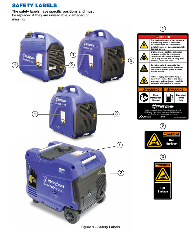
Safe operation is a prerequisite for the use of generators, and the document specifies multidimensional safety requirements that are applicable to all models.
1. Environment and placement safety
Operating environment: Only allowed to operate in outdoor ventilated areas, at least 1.8 meters away from doors, windows, and ventilation openings. It is strictly prohibited to use indoors, in garages, tents, and other enclosed spaces to prevent carbon monoxide poisoning (exhaust gas is colorless, odorless, and highly toxic).
Placement requirements: It must be placed on a horizontal, solid, and dry surface, avoiding loose areas such as sand and grass (to prevent debris from blocking the air vent). It is prohibited to operate in rainy, snowy, humid environments or floorplain areas to prevent short circuits.
Distance requirement: Keep at least 1.8 meters away from buildings, flammable materials, and other equipment to avoid high-temperature components igniting debris.
2. Electricity safety
Operation specifications: It is forbidden to touch the equipment with wet hands, and it is strictly prohibited to start the equipment when it is wet; Stay away from strong conductive areas such as metal decks and steel plants to reduce the risk of electric shock.
Line connection: Only use intact and grounded three core extension cables, and do not use damaged, knotted, or coiled cables; When connecting fixed circuits (such as household circuits), it must be operated by a certified electrician and self wiring is strictly prohibited.
Load limitation: It is prohibited to touch the live terminals or exposed wires of running equipment, and multiple generators must not be connected to the same load, extension lines, or fixed circuits; It is strictly prohibited to supply power to medical support equipment.
3. Fuel safety
Fuel specification: Only use unleaded gasoline with octane rating ≥ 91 and ethanol content ≤ 10%. Ethanol free gasoline is preferred to avoid fuel deterioration affecting equipment.
Filling specification: It is necessary to fill in the outdoor ventilated area, stop the machine and cool it down until the muffler shell is not hot to the touch before proceeding; Clean the surrounding impurities before opening the fuel cap, slowly add fuel, and do not exceed the red mark in the fuel tank (reserved expansion space) to avoid fuel spillage.
Fire prevention requirements: Keep away from sparks, open flames (matches, cigarettes), and electronic devices (mobile phones, intercoms) when refueling; The equipment operation area needs to be equipped with ABE or BE portable fire extinguishers; If there is a fuel leak, wipe it clean immediately and wait for the area to dry before starting the equipment.
Storage requirements: Fuel containers should be stored in a well ventilated area, away from flammable materials and sources of ignition, and fuel should not be used as a cleaning agent.
4. Special safety warnings
High temperature protection: During equipment operation, some components (muffler, engine) have extremely high temperatures, so avoid touching them. The "Hot Surface" warning label should be marked on the equipment and kept clear and visible.
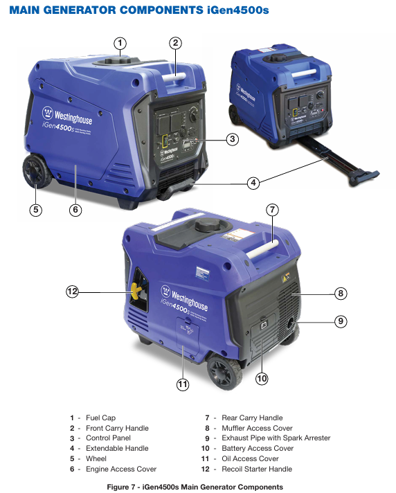
Misstart protection: Special attention should be paid to the remote start function of iGen4500s. When not in use, the engine control switch should be placed in the "STOP" position, and the remote control should be properly stored to avoid accidental start; Before starting the remote control, it is necessary to ensure that there are no safety hazards within the device's line of sight.
Maintain safety: Before maintenance, remove the spark plug cap to prevent accidental start-up; Do not open the oil filling port when the engine is hot (high pressure in the crankcase may cause burns from hot oil injection), and wait for a few minutes before operation.
Product configuration and functional differences
The core structure of the four models is consistent, all of which are portable inverter generators driven by air-cooled, four stroke gasoline engines, supporting pure sine wave output. However, there are differences in power, interface, and functionality, making them suitable for different scenarios.
1. General core functions
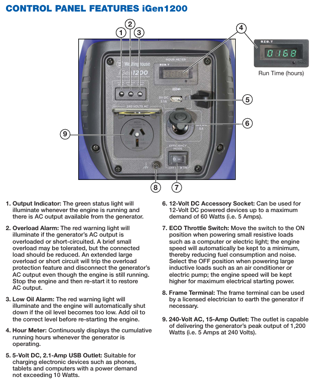
Output type: Supports 240V AC (50Hz, single-phase), 5V DC USB (some models support 12V DC) output, meeting various load requirements such as home appliances, electronic devices, tools, etc.
Protection function: All are equipped with low oil automatic shutdown, overload protection, and short circuit protection. When the oil is low, the red alarm light will light up and the machine will shut down. When overloaded/short circuited, the AC output will be disconnected and needs to be reset before use.
ECO throttle control: When turned on (in light load scenarios such as computers and lights), the engine speed automatically adapts to the load, reducing fuel consumption and noise; After shutdown (in heavy load scenarios such as air conditioning and water pumps), the engine maintains high speed to ensure starting power.
Other common configurations: hour meter (cumulative running time), waterproof interface (IP44 level), frame grounding terminal (can be grounded by an electrician).
2. Model specific configurations and parameter differences
Category iGen1200 iGen2200 iGen2500 iGen4500s
Engine parameters: displacement of 54cm ³, maximum speed of 5200rpm, oil capacity of 250mL, displacement of 79cm ³, maximum speed of 5300rpm, oil capacity of 350mL, displacement of 98cm ³, maximum speed of 5500rpm, oil capacity of 350mL, displacement of 224cm ³, maximum speed of 3600rpm, oil capacity of 600mL, including battery (sealed maintenance free)
Power parameters: continuous power 1000W, starting power 1200W, continuous power 1800W, starting power 2200W, continuous power 2200W, starting power 2500W, continuous power 3700W, starting power 4500W, including output power meter
Interface configuration: 1 x 240V AC (15A), 1 x 12V DC (5A, 60W), 1 x 5V USB (2.1A, 10W), 1 x 240V AC (15A), 1 x 5V USB (2.1A, 10W), 1 x 240V AC (15A), 1 x 5V USB (2.1A, 10W), 2 x 240V AC (15A), 1 x 12V DC (8A, 100W), 1 x 5V USB (2.1A, 10W)
Starting method: manual start, manual start, manual start+electric start+wireless remote control start (starting up to 50 meters and stopping at 25 meters)
Special configuration - Data center (cyclic display of accumulated running time, remaining running time, output power, fuel level, output voltage), telescopic handle+wheels (easy to move), fuel gauge
Dimensions and weight: length 463 x width 262 x height 395mm, dry weight 15kg, wet weight 17kg, length 500 x width 285 x height 450mm, dry weight 21kg, wet weight 24.5kg, length 500 x width 285 x height 450mm, dry weight 21.5kg, wet weight 25kg, length 650 x width 480 x height 520mm, dry weight 49.5kg, wet weight 60kg
3. Accessories list (included as standard with the box)
General accessories: SAE 10W-30 engine oil (250mL for iGen1200, 350mL for iGen2200/2500, 600mL for iGen4500s), fuel funnel, spark plug socket wrench, user manual.
Exclusive accessory: iGen4500s comes with an additional wireless remote key.
Complete operation process (detailed explanation by model)
1. Preparation before startup (applicable to all models)
Environmental inspection: Confirm that it is placed in a ventilated outdoor area, level and dry, with appropriate spacing and no flammable materials in close proximity.
Oil inspection:
Engine oil: The new engine has no engine oil and needs to be filled with SAE 10W-30 engine oil of the corresponding capacity according to the model (15W-40 can be replaced in high temperature environments). The oil level should be checked at the bottom edge of the oil filling port (starting too low can damage the engine).
Fuel: Add unleaded gasoline of grade 91 or above, do not overfill, and check for leaks after refueling.
Load disconnection: Ensure that all electrical appliances and tools are not connected to the generator interface or have turned off the power to avoid load shock during startup.
Other checks: Confirm that the spark plug cap is securely connected, the air filter is unobstructed, and the fuel cap vent is in the "ON" position (iGen1200/2200/2500).
2. Startup operation (by model)
(1) IGen1200 startup
Turn the fuel cap vent to the "ON" position.
Rotate the engine and fuel control switch counterclockwise to the "ON" position.
Cold engine start: Push the air damper lever to the right to the "START" position; Heat engine restart: Keep the throttle lever in the left "RUN" position.
Press and hold the device with one hand, and pull the starter rope with the other hand. Slowly pull until resistance is felt, then quickly pull it out with force. After starting, slowly release the rope (to avoid damaging the starter with a loud bounce).
After the engine starts, wait for it to warm up, gradually push the throttle lever to the left to the "RUN" position, and then connect the load.
(2) IGen2200/2500 startup
Turn the fuel cap vent to the "ON" position.
Cold engine start: Rotate the engine, fuel, and throttle control switches clockwise to the "CHOKE" position; Heat engine restart: Turn to the "ON" position.
Start the engine using the iGen1200 manual start method.
After the engine is warmed up, turn the control switch counterclockwise to the "ON" position and then connect the load.
(3) IGen4500s startup (three ways)
① Electric start
Turn the fuel control switch clockwise to the "ON" position.
Press and hold the engine control switch to the "START" position for 1 second, then release it and it will automatically pop to the "AUTO RUN" position. The electric starter will start the engine (if it fails to start once, the device will automatically retry).
Directly connect the load (no need to manually adjust the air door, the equipment comes with an automatic air door).
② Manually start
Ensure that the battery is connected (it cannot start when there is no power, and needs to be charged or replaced first).
Turn the fuel control switch to "ON" and push the engine control switch to the middle "AUTO RUN" position.
Start by manually pulling and connect the load after startup.
③ Wireless remote control start
Turn the fuel control switch to "ON" and push the engine control switch to the "AUTO RUN" position.
Aim the remote control at the device, press and hold the "ON" button for 1 second, then release it to start the engine (the effective distance of the remote control is about 50 meters).
Connect the load and press the "OFF" button on the remote control to stop the machine within 25 meters after starting.
3. Load connection specifications
240V AC load: directly or through an extension cord connected to the socket, open the waterproof cover to insert; Only supports 10A or 15A three pin plugs, and it is prohibited to connect 20A plugs (which may cause overload).
12V DC load (iGen1200/4500s): Connect using a cigarette lighter plug, with an extension cord length not exceeding 3.5 meters, and a load power not exceeding 60W (iGen1200)/100W (iGen4500s). It is prohibited to insert a car cigarette lighter (high temperature may ignite fuel).
5V DC USB load: connected using a standard A-type USB plug, with an extension cable length of no more than 2 meters and a load power of no more than 10W (suitable for charging mobile phones, tablets, and other devices).
Power calculation:
Pure resistive load (light bulb, toaster): starting power=operating power.
Motor loads (air conditioning, water pumps): starting power for small portable devices=operating power x 1.2, for large fixed devices=operating power x 3.5, total load operating power ≤ generator continuous power, total starting power ≤ generator starting power.
4. Shutdown operation (divided into normal/emergency)
(1) Normal shutdown
First, turn off or unplug all connected loads.
Run the engine without load for 1 minute to cool down the engine and generator.
Operation by model:
IGen1200: Turn the control switch clockwise to "OFF" and turn the fuel cap vent to "OFF".
IGen2200/2500: Rotate the control switch counterclockwise to "OFF" and turn the fuel cap vent to "OFF".
IGen4500s: Press the engine control switch to "STOP", then turn the fuel control switch to "OFF"; Or press the "OFF" button on the remote control (to confirm that the device has stopped).
(2) Emergency stop
Quickly execute the shutdown operation steps according to the corresponding model without the need for idle cooling, suitable for emergency situations such as equipment failure and fire.
Maintenance and storage (key to extending equipment lifespan)
1. Maintain the overall principle
Before maintenance, it is necessary to shut down, cool down, remove the spark plug cap, and operate in a ventilated area; Avoid skin contact with engine oil and fuel, wear protective gloves and glasses, and wash hands after operation.
Only use genuine Westinghouse accessories or accessories specified in the manual, non genuine may damage the device.
In harsh environments (high temperature, high humidity, high dust, high load), it is necessary to shorten the maintenance cycle.
2. Regular maintenance schedule (divided into cycles)
Maintain the project for the first 20 hours/1 month (first come) every 50 hours/3 months (first come) every 100 hours/6 months (first come) every 250 hours/1 year (first come) before each use
Check the engine oil level, if it is insufficient, add and thoroughly replace the oil - thoroughly replace the oil-
Visual inspection of air filter for cleanliness - Cleanliness (shortened cycle in dusty environment) --
Spark plug - check and clean, adjust the gap (0.7mm), replace (see the model in the table below)
Fuel Filter Screen - Cleaning-
Spark Arrester (iGen2200/2500/4500s) - Cleaning-
Inspect and clean the exterior surface to ensure that the ventilation openings are unobstructed-
Valve clearance (professional maintenance) - check and adjust
Combustion chamber (professional maintenance) - cleaned every 500 hours/2 years
3. Detailed explanation of key maintenance operations
(1) Engine oil maintenance
Oil specifications: Use four stroke engine oil with API grade ≥ SF, SAE 10W-30 for conventional environments, 15W-40 for temperatures>40 ℃, and prohibit the use of two-stroke engine oil or mixed engine oil.
Check oil level: Place the equipment horizontally, cool down after shutdown, open the oil filling port, and the oil level should be at the bottom edge of the filling port (if it is lower than, add; if it overflows, drain excess oil).
Change engine oil:
After cooling down, open the engine/oil access cover and place a drain pan under the filling port.
Unscrew the oil filler plug and tilt the equipment to drain the old oil.
Reset the device, add new engine oil of the corresponding capacity according to the model, check that the oil level meets the standard, tighten the screw plug, and cover it.
Old engine oil should be disposed of according to environmental protection requirements and should not be dumped at will.
(2) Air filter maintenance
Cleaning cycle: every 50 hours or 3 months, shortened to every 25 hours in dusty environments.
Cleaning steps:
Shutdown for cooling, open the engine access cover, and remove the air filter cover according to the model (iGen1200 press the lock, iGen2200/2500 tighten the screw, iGen4500s twist the lock).
Take out the foam filter element, clean it with household detergent+warm water or nonflammable solvent, and slowly squeeze it (no twisting or tearing).
Rinse with clean water, squeeze and drain, apply a small amount of clean engine oil (to enhance filtration effect), and then squeeze out excess oil.
Install the filter element and cover in the original direction.
(3) Spark plug maintenance
Change model: iGen1200 uses Torch A5RTC, iGen2200/2500 uses Torch E6RTC, iGen4500s uses Torch F7RTC (can be replaced with corresponding models such as Bosch and Champion).
Inspection and Cleaning:
Shutdown for cooling, remove the spark plug access cover, and remove the spark plug cap.
Use a spark plug socket wrench to unscrew the spark plug counterclockwise, and cover the cylinder port with a cloth to prevent debris from entering.
Check the electrode: If the insulation layer is cracked, the electrode is severely worn, or there is excessive carbon deposition, replace it directly; If the condition is good, clean the carbon deposits with a wire brush and adjust the gap to 0.7mm (achieved by bending the side electrode).
When installing, first tighten the spark plug by hand to fit the cylinder head, and then tighten it with a wrench (tighten the old spark plug by 1/8-1/4 turn, and the new spark plug by 1/4-1/2 turn, with a torque not exceeding 12Nm (iGen1200)/17Nm (other models)).
Insert the spark plug cap back and cover it.
(4) Fuel filter maintenance
Cleaning cycle: Every 100 hours or 6 months, or after refueling from non gas station sources.
Cleaning steps:
Shutdown for cooling, clean the area around the fuel cap, open the fuel cap, and remove the fuel filter from the fuel tank (manually pull it out).
Pour out impurities and fuel from the filter screen, and blow the filter screen with low-pressure compressed air from the outside to remove fine sand.
Insert the filter back in the original direction and tighten the fuel cap.
4. Long term storage (divided into cycles)
(1) 1-3 months of storage
Wipe the appearance of the equipment according to cleaning standards to ensure no oil stains or dust.
Add fuel stabilizer to the fuel tank and then fill it with fresh fuel (reducing air in the tank to prevent fuel deterioration).
Start the engine and run it for 10 minutes, allowing the stabilizer containing fuel to flow through the entire fuel system.
Stop the machine according to the normal shutdown steps, turn off the fuel control switch and fuel cap vent (iGen1200/2200/2500).
Store in a dry, clean, and ventilated room, away from direct sunlight.
(2) More than 3 months of storage (core anti fuel deterioration and internal corrosion)
Clean the appearance of the equipment.
Drain fuel: Open the fuel cap, remove the filter screen, and use a siphon pump to extract fuel from the fuel tank; Open the drain hose at the bottom of the carburetor again, loosen the drain screw, and empty the residual fuel in the carburetor (the fuel needs to be treated environmentally).
Start the engine and run it without load until the fuel runs out, then automatically shut down (completely emptying the fuel system).
Replace the engine oil (old oil contains impurities, long-term storage can corrode the engine).
Remove the spark plug, pour 1 tablespoon of clean engine oil into the cylinder, pull the starting rope several times by hand (to evenly apply the oil to the cylinder wall), and then reinstall the spark plug.
Pull the starting rope until resistance is felt (piston in compression stroke, valve closed), maintain this state for storage, and prevent internal corrosion.
Store in a dry, clean, and ventilated room, away from heat sources and flammable materials.
(3) Enable after storage
Check the oil level of the machine, add if it is insufficient; If cylinder oil has been added during storage, the exhaust may briefly emit smoke after starting, which is a normal phenomenon.
Add fresh fuel (prohibit the use of stored old fuel).
Follow the usual startup steps, run without load for 5 minutes first, and then connect the load.
5. Transportation specifications
Before transportation: Stop the machine and turn off the fuel control switch and fuel cap vent; If the equipment is already running, it needs to be cooled before transportation; Drain the fuel when conditions permit to avoid leakage.
During transportation: Keep the equipment level and prohibit flipping or tilting (to prevent oil and fuel leakage from damaging components); Only by using the device's built-in handle for handling, the iGen4500s can be moved using a telescopic handle and wheels. Dragging the wheels or lifting the device with the telescopic handle is prohibited.
Loading requirements: Fix it on the transport vehicle with ropes to avoid shaking and collision during transportation.
Troubleshooting (common problems+solutions)
The document provides a detailed troubleshooting table, and the following are the core troubleshooting steps for high-frequency problems, which are applicable to all models.
1. The engine cannot start or runs unstably after starting
Potential cause solutions
Check the oil level for low oil level and add it to the standard position
Insufficient or deteriorated fuel/water content, add fresh fuel; If the fuel deteriorates, empty the fuel tank and carburetor before refilling
Close the fuel cap vent (iGen1200/2200/2500) and turn it to the "ON" position
Control switch position error iGen1200: Turn to "ON"; IGen2200/2500: Cold engine to "CHOKE", hot engine to "ON"; IGen4500s: Fuel switch "ON", engine switch "AUTO RUN"
Improper adjustment of the air door: The air door of the refrigeration unit is not opened (adjusted to "CHOKE/START"), and the air door of the heating unit is not closed (adjusted to "ON/RUN")
Spark plug fault check whether the spark plug is loose, carbon deposits or improper clearance, clean, adjust or replace it
Air filter clogged, clean or replace air filter
Load not disconnected, unplug all loads and restart
2. Engine running but no output (AC/DC)
Potential causes and solutions for output types
Open all loads due to 240V AC overload or short circuit, press the reset button on iGen4500s, and restart the equipment on other models; Connect the load separately to troubleshoot the faulty equipment
The 240V AC plug is not securely plugged in or there is a cable malfunction. Re plug the plug and replace it with a known intact cable for testing
5V/12V DC load overload or short circuit disconnect the load, restart the equipment, and check if the load power exceeds the rated value
Contact authorized service dealers for internal faults of all output devices for maintenance
3. Engine shutdown during operation
Potential cause solutions
Fuel depletion or deterioration, add fresh fuel
The oil level is too low. Add oil to the standard position
Loosening spark plug cap and tightening spark plug cap
Overload or short circuit disconnect the load, restart the equipment, and check the total load power
Fuel filter clogged, clean the fuel filter
4. Unstable engine speed
Potential cause solutions
Load power fluctuation is a normal phenomenon under ECO mode and does not need to be addressed
Disconnect the load when the engine is not preheated, and run it without load for 2 minutes before reconnecting
Improper adjustment of the air door during heating, the air door is not adjusted to the "ON/RUN" position
Fuel deterioration or air filter blockage, replace fuel, clean air filter
- OMRON
- ABB
- General Electric
- EMERSON
- Honeywell
- HIMA
- ALSTOM
- Rolls-Royce
- MOTOROLA
- Rockwell
- Siemens
- Woodward
- YOKOGAWA
- FOXBORO
- KOLLMORGEN
- MOOG
- KB
- YAMAHA
- BENDER
- TEKTRONIX
- Westinghouse
- AMAT
- AB
- XYCOM
- Yaskawa
- B&R
- Schneider
- KONGSBERG
- NI
- WATLOW
- ProSoft
- SEW
- ADVANCED
- Reliance
- TRICONEX
- METSO
- MAN
- Advantest
- STUDER
- DANAHER MOTION
- Bently
- Galil
- EATON
- MOLEX
- DEIF
- B&W
- ZYGO
- Aerotech
- DANFOSS
- Beijer
- Moxa
- Rexroth
- Johnson
- WAGO
- TOSHIBA
- BMCM
- SMC
- HITACHI
- HIRSCHMANN
- Application field
- XP POWER
- CTI
- TRICON
- STOBER
- Thinklogical
- Horner Automation
- Meggitt
- Fanuc
- Baldor
- SHINKAWA
- Other Brands
- UniOP
- KUKA
- Iba
- Beckhoff
-
 Basler D90 96801 100 PCB Card
 -
 Basler XR2002F Voltage Regulator (110 VAC, 48-480 Hz)
 -
 Basler SR8A-2B14B3A Regulator
 -
 Basler 9561500100 Module
 -
 Basler DECS-400 BE1-11 System
 -
 Basler DECS-100-B15 Excitation Control
 -
 Basler SCP 210 Frequency Controller
 -
 Basler SR4A-2B15B3A Static Voltage Regulator
 -
 Basler BE1-32R Power Relay
 -
 Basler PIA2400-17GM Power Interface Adapter
 -
 Basler MVC 232 Manual Voltage Control Module
 -
 Basler SSR 32-12 Static Voltage Regulator
 -
 Basler 5MW AVR Generator Voltage Regulator
 -
 Basler VR63-4B Voltage Regulator
 -
 Basler DECS-100-A05 AVR for Engine Generator
 -
 Basler DECS-100-B15 Automatic Voltage Regulator
 -
 Basler BE1-32R Directional Power Relay
 -
 Basler BE1-87B Differential Relay
 -
 Basler UFOV 260A Protective Module
 -
 Basler 9-2614-02-100 PCB Rev M
 -
Basler DECS-100-B15 Digital AVR
-
 Basler 9284900103 PS DECS-400N
 -
 Basler D4N3H1U Intertie Protection
 -
 Basler DECS-100-B15 A15 AVR
 -
 Basler KR4F Voltage Regulator
 -
 Basler BE26434 T14 Transformer
 -
 Basler SR8A-2B15B3A Regulator
 -
 Westinghouse 774B472A12 AR Relay
 -
Basler DECS-100-B15 AVR
-
Basler XR2002F Regulator 110V
-
Basler SR125-E Static Regulator
-
 Basler SSR 125-12 Regulator
 -
 Basler MOC2599 Motor Pot
 -
 Basler BE1-DFPR Feeder Relay
 -
 Basler CBS 305 Current Boost
 -
 Basler BE1-25 AutoSync
 -
 Basler MVC 300 Voltage Control
 -
 Basler BE3-25A AutoSync
 -
 Basler KR7FF Static Regulator
 -
 Basler 90-49000-100 Regulator
 -
 Basler 880 kVA Dry Type Transformer Specs
 -
 Basler Electric BE1-25 Sync-Check Relay Specs
 -
 Basler SSR 125-12 Voltage Regulator Specs
 -
 Basler Electric BE1-851 Overcurrent Relay Review
 -
Basler Electric 149D930G02 Control Sub-Assembly
-
 Basler Electric BE1-81O/UT Frequency Relay Specs
 -
 Basler Electric BE1-51/27C Overcurrent Relay
 -
 Basler Electric 149D956G02 Industrial Component
 -
Basler Electric BE1-51A Overcurrent Relay Specs
-
 Basler Electric BE1-40Q Loss of Excitation Relay
 -
 Basler DECS-200 Excitation Control System
 -
 Basler DECS-200 Voltage Regulator 56-277V AC / 125V DC
 -
Basler BE1-87T Transformer Differential Relay
-
 Basler RDP-110-S1 Protection Relay
 -
 Basler BE1-700V Digital Protective Relay
 -
 Basler BE1-951 Overcurrent Protection System
 -
 Basler DECS-300 Digital Excitation Control
 -
 Basler DECS-200 Digital Excitation Control
 -
 Basler DECS-200-1C Excitation Control System
 -
Basler DECS-200-1L Digital Excitation Control
-
 Basler Electric BE1-GPS Generator Protection System
 -
Basler Electric DECS-200-1C Digital Excitation Controller
-
 Basler Electric DECS125-15 Excitation Control with Power Module
 -
 Basler Electric BE1-87G Differential Relay
 -
 Basler Electric BE1-11 Protection System I5A3M2P2N0EA00
 -
Basler Electric DECS-200-1C Excitation Control System
-
Basler Electric BE1-11g Generator Protection Relay
-
Basler Electric DECS 125-15-B2C1 V2.0.9 Excitation Control
-
 Basler Electric BE1-81O/UT3ED1JA7N2F Frequency Relay
 -
Basler Electric BE1-81O/UT3EE1YB7N1F Frequency Relay
-
 Basler Electric DECS-200-1L Digital Excitation Control System
 -
Basler DECS125-15-B2C1 Excitation Control
-
 Basler 9507900205 SSR Retrofit Voltage Regulator
 -
 Basler BE2000E Digital Voltage Regulator
 -
 Basler BE1-GPS Generator Protection System
 -
Basler DECS-250-CN1CN1N Digital Excitation Control
-
 Basler DGC-2020 Genset Controller
 -
 Basler BE1-81O UT3ED1LA7N0F Frequency Relay (Variant)
 -
 Basler BE1-81O UT3EE1YA9S0F Frequency Relay (Variant)
 -
Basler BE1-81O Over/Under Frequency Relay
-
Basler DECS125-15 Digital Excitation Control
-
Basler Electric BE1-951 Overcurrent Protection System
-
 Basler Electric BE1-700V Digital Protective Relay
 -
 Basler Electric APR63-5 Automatic Voltage Regulator
 -
Basler Electric BE1-851 Overcurrent Protection System
-
Basler Electric DECS-250-LN1SN1N Excitation Control
-
 Basler Electric BE1-87T Transformer Differential Relay
 -
Basler Electric DECS-200-1L Excitation Control System
-
 Basler Electric 9310300100 DECS-300 Excitation Control
 -
 Basler Electric SSE-N 125-4.5KW Shunt Exciter Regulator
 -
 Basler Electric DGC-2020HD-5NS1DNSBA Genset Controller
 -
Basler Electric BE1-81-O/UT3EE1JB7N1F Frequency Relay
-
Basler Electric BE1-81T1EE1WA0N1F Frequency Relay
-
 Basler Electric BE1-25M1EA6PN5R1F Sync-Check Relay
 -
 Basler Electric BE1-GPS Generator Protection System
 -
Basler Electric DECS-250-LN1SN1N Excitation Control Rev V
-
 Basler Electric DECS-250-CN2CN1N Excitation Control
 -
Basler Electric BE1-50/51B-207 Overcurrent Relay
-
Basler Electric DECS-300-C0N0 Excitation Control System
-
Basler Electric DECS-200 Digital Excitation Control System
-
Basler Electric DECS-250-LN1CN1N Excitation Unit
-
Basler Electric DECS-250 LN2SA1D Excitation Unit Specs
-
Basler Electric BE1-87T Transformer Relay Review
-
Basler Electric BE1-11 Protection System
-
Basler Electric BE1-GPS100-E4N1H1N Protection System
-
 Allen-Bradley 442G-MABH-R Safety Module
 -
 Beckhoff CX1030-0111 PLC Assembly Profile
 -
 FANUC IC693CPU364 PLC Module
 -
 Orange Denmark Type 200816 220 PLC Specs
 -
 OMRON C200H-SNT31 Sysmac PLC Module
 -
 Allen Bradley 20AB022A3AYNANC0 PowerFlex 70
 -
 OMRON C200HW-PCU01 Position Control Unit
 -
 ABB AO845A-eA Analog Output Module
 -
 OMRON CJ1M-CPU22 CPU Unit
 -
 Allen Bradley 100-E265ED11 Contactor
 -
 Honeywell 51304511-100 Interface Module
 -
 SOLEXY BXF3S0101N0018 Gateway Module
 -
 OMRON CJ2H-CPU65 CPU Unit
 -
 Automation Direct GS2-45P0 AC Drive
 -
 M68-2000 2-Axis Motion CNC Controller
 -
 OMRON CJ1M-CPU11 V3.0 PLC CPU Unit
 -
 OMRON CJ1W-NC413 4-Axis Positioning Controller
 -
 OMRON 3G2A3-PRO16 Programming Console HMI
 -
 Siemens 3VT8440-2AA04-2GA2 Molded Case Circuit Breaker
 -
 Siemens 3RT5045 Contactor Series
 -
 OMRON C200HS-CPU01-E SYSMAC PLC Controller
 -
 OMRON C500-NC103-E Positioning Control Unit
 -
 OMRON CJ1W-TC001 Temperature Control Unit


