
Westinghouse iGen4500DFc Dual Fuel Digital Variable Frequency Generator
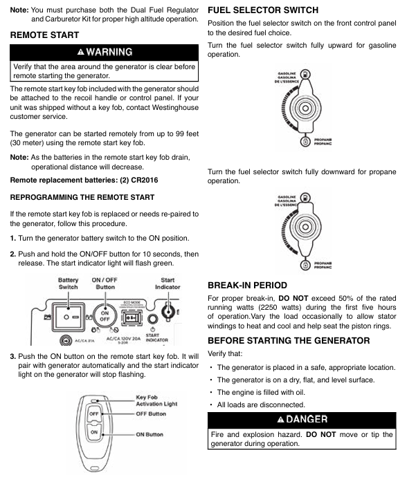
Stop the engine: Press the "START/STOP" stop button on the control panel (or the "OFF" button on the remote control) to shut down the engine.
Close the fuel valve: Close the fuel tank valve in gasoline mode, and close the cylinder valve in propane mode (tighten clockwise).
Long term shutdown: Turn off the battery switch, cover with a dust cover (plastic cover is prohibited to avoid moisture), and place in a dry and ventilated place.
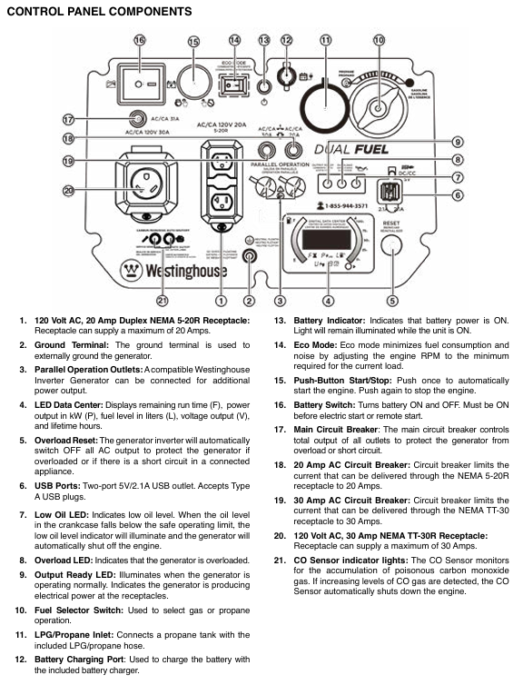
Installation and usage specifications
1. Installation and placement requirements
Placement environment:
Can only be used outdoors, at least 1.5 meters (5 feet) away from doors, windows, ventilation openings, and air conditioning units. It is prohibited to use indoors, in garages, basements, tents, and other enclosed/semi enclosed spaces to prevent carbon monoxide poisoning.
Place on a hard and flat surface (cement floor, wooden board) to avoid sand, grass debris, and soil blocking the heat dissipation outlet; Do not operate on slopes to prevent uneven oil lubrication or fuel leakage.
Grounding requirements:
When only using a socket for direct power supply, there is no need for additional grounding (generator neutral line floating design).
If connecting to the building power supply system (such as a household distribution box), a professional electrician must install a transfer switch (in accordance with NFPA 70 standard) and connect the generator grounding terminal to the grounding electrode (grounding resistance ≤ 4 Ω).
Protection requirements: Do not use in rainy, snowy, or humid environments to avoid rainwater splashing onto control panels or sockets; If temporary outdoor use is required, a rain shelter should be built (to ensure ventilation) and it is prohibited to cover the generator.
2. Extension cable and load adaptation
(1) Extension cable selection
Load current extension cable length ≤ 15 meters Extension cable length ≤ 30 meters Precautions
≤ 10A (such as lamps, computers) 16AWG 3-core grounding extension wire 14AWG 3-core grounding extension wire must use outdoor dedicated, undamaged, and well grounded extension wire
10-20A (such as microwave ovens and small air conditioners) 14AWG 3-core grounding extension cable 12AWG 3-core grounding extension cable. The shorter the length of the extension cable, the better to reduce voltage drop
20-30A (such as RV RVs, high-power water pumps) 12AWG 3-core grounding extension wire 10AWG 3-core grounding extension wire is prohibited from using multi joint extension wires to avoid overload and heating
(2) Common Load Adaptation Table
Equipment type Operating power (W) Starting power (W) Adaptation fuel mode Remarks
Laptop 60-100 60-100 gasoline/propane can activate ECO mode for the longest range
55 inch LED TV 80-150 80-150 gasoline/propane can be connected to the light fixture simultaneously
Household refrigerator (double door) 700-1000 2000-2500 gasoline with high starting power, needs to be started separately before connecting other devices
1.5 horsepower air conditioner (window type) 1200-1500 3000-3500 gasoline with ECO mode off to ensure sufficient peak power
RV RV (regular load) 1500-2500 3000-4000 gasoline/propane use 30A dedicated socket to avoid starting multiple high-power devices at the same time
1/3 horsepower water pump 800-1000 2000-2500 may trigger overload protection when starting gasoline, and other loads need to be disconnected
3. Parallel operation (parallel wires need to be purchased separately)
Applicable scenario: When a single generator has insufficient power (such as supplying power to 2 air conditioners), it can be connected in parallel with another compatible Westinghouse variable frequency generator (such as iGen4500DFc, iGen4000).
Operation steps:
Turn off two generators, disconnect all loads, and ensure that the battery switch is turned off.
Connect parallel wires: Connect the black wire to the black parallel interface of two generators, connect the red wire to the red interface, and connect the green grounding wire to the grounding terminal.
Start two generators in sequence and wait for their respective output ready indicator lights to turn on (green).
Connect the load to the socket of one of the generators, and the load will be shared between the two generators, with a total rated power ≤ the sum of the rated powers of the two generators.
Attention: Do not enable ECO mode when parallel connection is made; The fuel mode of the two generators must be consistent (both gasoline or propane); The total rated power of the load is ≤ 80% of the total rated power to avoid overload.
Maintenance and upkeep
1. Regular maintenance schedule
Maintenance project maintenance cycle operation content
Oil check: Before each use or after every 8 hours of operation, take out the dipstick, wipe it clean, insert and tighten it, take it out and check the liquid level. If it is below the L mark, add 10W-30 oil
The first 25 hours or 1 month of oil change; After heating up every 50 hours or 6 months, drain the oil (with the drain bolt at the bottom), replace the new engine oil (0.6L), and replace the drain bolt copper washer (Part # 94007)
Clean the air filter every 50 hours or 6 months; In dusty environment, shorten it to 25 hours, take out the foam filter element, clean it with detergent, soak a small amount of engine oil after drying (squeeze out the excess), and reinstall; Replace if damaged (Part # 5691)
- OMRON
- ABB
- General Electric
- EMERSON
- Honeywell
- HIMA
- ALSTOM
- Rolls-Royce
- MOTOROLA
- Rockwell
- Siemens
- Woodward
- YOKOGAWA
- FOXBORO
- KOLLMORGEN
- MOOG
- KB
- YAMAHA
- BENDER
- TEKTRONIX
- Westinghouse
- AMAT
- AB
- XYCOM
- Yaskawa
- B&R
- Schneider
- KONGSBERG
- NI
- WATLOW
- ProSoft
- SEW
- ADVANCED
- Reliance
- TRICONEX
- METSO
- MAN
- Advantest
- STUDER
- DANAHER MOTION
- Bently
- Galil
- EATON
- MOLEX
- DEIF
- B&W
- ZYGO
- Aerotech
- DANFOSS
- Beijer
- Moxa
- Rexroth
- Johnson
- WAGO
- TOSHIBA
- BMCM
- SMC
- HITACHI
- HIRSCHMANN
- Application field
- XP POWER
- CTI
- TRICON
- STOBER
- Thinklogical
- Horner Automation
- Meggitt
- Fanuc
- Baldor
- SHINKAWA
- Other Brands
- UniOP
- KUKA
- Iba
- Beckhoff
-
 Basler D90 96801 100 PCB Card
 -
 Basler XR2002F Voltage Regulator (110 VAC, 48-480 Hz)
 -
 Basler SR8A-2B14B3A Regulator
 -
 Basler 9561500100 Module
 -
 Basler DECS-400 BE1-11 System
 -
 Basler DECS-100-B15 Excitation Control
 -
 Basler SCP 210 Frequency Controller
 -
 Basler SR4A-2B15B3A Static Voltage Regulator
 -
 Basler BE1-32R Power Relay
 -
 Basler PIA2400-17GM Power Interface Adapter
 -
 Basler MVC 232 Manual Voltage Control Module
 -
 Basler SSR 32-12 Static Voltage Regulator
 -
 Basler 5MW AVR Generator Voltage Regulator
 -
 Basler VR63-4B Voltage Regulator
 -
 Basler DECS-100-A05 AVR for Engine Generator
 -
 Basler DECS-100-B15 Automatic Voltage Regulator
 -
 Basler BE1-32R Directional Power Relay
 -
 Basler BE1-87B Differential Relay
 -
 Basler UFOV 260A Protective Module
 -
 Basler 9-2614-02-100 PCB Rev M
 -
Basler DECS-100-B15 Digital AVR
-
 Basler 9284900103 PS DECS-400N
 -
 Basler D4N3H1U Intertie Protection
 -
 Basler DECS-100-B15 A15 AVR
 -
 Basler KR4F Voltage Regulator
 -
 Basler BE26434 T14 Transformer
 -
 Basler SR8A-2B15B3A Regulator
 -
 Westinghouse 774B472A12 AR Relay
 -
Basler DECS-100-B15 AVR
-
Basler XR2002F Regulator 110V
-
Basler SR125-E Static Regulator
-
 Basler SSR 125-12 Regulator
 -
 Basler MOC2599 Motor Pot
 -
 Basler BE1-DFPR Feeder Relay
 -
 Basler CBS 305 Current Boost
 -
 Basler BE1-25 AutoSync
 -
 Basler MVC 300 Voltage Control
 -
 Basler BE3-25A AutoSync
 -
 Basler KR7FF Static Regulator
 -
 Basler 90-49000-100 Regulator
 -
 Basler 880 kVA Dry Type Transformer Specs
 -
 Basler Electric BE1-25 Sync-Check Relay Specs
 -
 Basler SSR 125-12 Voltage Regulator Specs
 -
 Basler Electric BE1-851 Overcurrent Relay Review
 -
Basler Electric 149D930G02 Control Sub-Assembly
-
 Basler Electric BE1-81O/UT Frequency Relay Specs
 -
 Basler Electric BE1-51/27C Overcurrent Relay
 -
 Basler Electric 149D956G02 Industrial Component
 -
Basler Electric BE1-51A Overcurrent Relay Specs
-
 Basler Electric BE1-40Q Loss of Excitation Relay
 -
 Basler DECS-200 Excitation Control System
 -
 Basler DECS-200 Voltage Regulator 56-277V AC / 125V DC
 -
Basler BE1-87T Transformer Differential Relay
-
 Basler RDP-110-S1 Protection Relay
 -
 Basler BE1-700V Digital Protective Relay
 -
 Basler BE1-951 Overcurrent Protection System
 -
 Basler DECS-300 Digital Excitation Control
 -
 Basler DECS-200 Digital Excitation Control
 -
 Basler DECS-200-1C Excitation Control System
 -
Basler DECS-200-1L Digital Excitation Control
-
 Basler Electric BE1-GPS Generator Protection System
 -
Basler Electric DECS-200-1C Digital Excitation Controller
-
 Basler Electric DECS125-15 Excitation Control with Power Module
 -
 Basler Electric BE1-87G Differential Relay
 -
 Basler Electric BE1-11 Protection System I5A3M2P2N0EA00
 -
Basler Electric DECS-200-1C Excitation Control System
-
Basler Electric BE1-11g Generator Protection Relay
-
Basler Electric DECS 125-15-B2C1 V2.0.9 Excitation Control
-
 Basler Electric BE1-81O/UT3ED1JA7N2F Frequency Relay
 -
Basler Electric BE1-81O/UT3EE1YB7N1F Frequency Relay
-
 Basler Electric DECS-200-1L Digital Excitation Control System
 -
Basler DECS125-15-B2C1 Excitation Control
-
 Basler 9507900205 SSR Retrofit Voltage Regulator
 -
 Basler BE2000E Digital Voltage Regulator
 -
 Basler BE1-GPS Generator Protection System
 -
Basler DECS-250-CN1CN1N Digital Excitation Control
-
 Basler DGC-2020 Genset Controller
 -
 Basler BE1-81O UT3ED1LA7N0F Frequency Relay (Variant)
 -
 Basler BE1-81O UT3EE1YA9S0F Frequency Relay (Variant)
 -
Basler BE1-81O Over/Under Frequency Relay
-
Basler DECS125-15 Digital Excitation Control
-
Basler Electric BE1-951 Overcurrent Protection System
-
 Basler Electric BE1-700V Digital Protective Relay
 -
 Basler Electric APR63-5 Automatic Voltage Regulator
 -
Basler Electric BE1-851 Overcurrent Protection System
-
Basler Electric DECS-250-LN1SN1N Excitation Control
-
 Basler Electric BE1-87T Transformer Differential Relay
 -
Basler Electric DECS-200-1L Excitation Control System
-
 Basler Electric 9310300100 DECS-300 Excitation Control
 -
 Basler Electric SSE-N 125-4.5KW Shunt Exciter Regulator
 -
 Basler Electric DGC-2020HD-5NS1DNSBA Genset Controller
 -
Basler Electric BE1-81-O/UT3EE1JB7N1F Frequency Relay
-
Basler Electric BE1-81T1EE1WA0N1F Frequency Relay
-
 Basler Electric BE1-25M1EA6PN5R1F Sync-Check Relay
 -
 Basler Electric BE1-GPS Generator Protection System
 -
Basler Electric DECS-250-LN1SN1N Excitation Control Rev V
-
 Basler Electric DECS-250-CN2CN1N Excitation Control
 -
Basler Electric BE1-50/51B-207 Overcurrent Relay
-
Basler Electric DECS-300-C0N0 Excitation Control System
-
Basler Electric DECS-200 Digital Excitation Control System
-
Basler Electric DECS-250-LN1CN1N Excitation Unit
-
Basler Electric DECS-250 LN2SA1D Excitation Unit Specs
-
Basler Electric BE1-87T Transformer Relay Review
-
Basler Electric BE1-11 Protection System
-
Basler Electric BE1-GPS100-E4N1H1N Protection System
-
 Allen-Bradley 442G-MABH-R Safety Module
 -
 Beckhoff CX1030-0111 PLC Assembly Profile
 -
 FANUC IC693CPU364 PLC Module
 -
 Orange Denmark Type 200816 220 PLC Specs
 -
 OMRON C200H-SNT31 Sysmac PLC Module
 -
 Allen Bradley 20AB022A3AYNANC0 PowerFlex 70
 -
 OMRON C200HW-PCU01 Position Control Unit
 -
 ABB AO845A-eA Analog Output Module
 -
 OMRON CJ1M-CPU22 CPU Unit
 -
 Allen Bradley 100-E265ED11 Contactor
 -
 Honeywell 51304511-100 Interface Module
 -
 SOLEXY BXF3S0101N0018 Gateway Module
 -
 OMRON CJ2H-CPU65 CPU Unit
 -
 Automation Direct GS2-45P0 AC Drive
 -
 M68-2000 2-Axis Motion CNC Controller
 -
 OMRON CJ1M-CPU11 V3.0 PLC CPU Unit
 -
 OMRON CJ1W-NC413 4-Axis Positioning Controller
 -
 OMRON 3G2A3-PRO16 Programming Console HMI
 -
 Siemens 3VT8440-2AA04-2GA2 Molded Case Circuit Breaker
 -
 Siemens 3RT5045 Contactor Series
 -
 OMRON C200HS-CPU01-E SYSMAC PLC Controller
 -
 OMRON C500-NC103-E Positioning Control Unit
 -
 OMRON CJ1W-TC001 Temperature Control Unit


