

The ABB UNITOL 1000 series is a compact, high-performance automatic voltage regulator (AVR), consisting of three models: UNITOL 1005, 1010, and 1020, designed specifically for low-power range applications, setting a new benchmark in the industry with functionality, reliability, and connectivity. This series adopts separate communication and control processors, equipped with non-volatile flash storage for event and data logs, supports Ethernet time synchronization and event timestamps, and is suitable for various industrial scenarios.
ABB UNITOL 1000 series automatic voltage regulator
Product overview
The ABB UNITOL 1000 series is a compact, high-performance automatic voltage regulator (AVR), consisting of three models: UNITOL 1005, 1010, and 1020, designed specifically for low-power range applications, setting a new benchmark in the industry with functionality, reliability, and connectivity. This series adopts separate communication and control processors, equipped with non-volatile flash storage for event and data logs, supports Ethernet time synchronization and event timestamps, and is suitable for various industrial scenarios.
Product model and core parameters
UNITROL 1005:5A continuous, 10A peak, for low-end excitation applications, shares software source code and simulation model with 1010/1020, supports USB, Ethernet, no HMI, analog I/O is 2 inputs, digital I/O is 8 inputs+4 outputs
UNITROL 1010:10A continuous, 20A peak, compact device with limited functionality, same mechanical size and interface as 1020, supports Ethernet RS485(Modbus RTU/VDC)、USB, Analog I/O consists of 3 inputs and 2 outputs, while digital I/O consists of 4 inputs and 8 inputs/outputs
UNITROL 1020:20A continuous, 38A peak, high performance, with a local human-machine interface, comprehensive functions, interface identical to 1010, I/O configuration identical to 1010, and an intuitive local control panel added
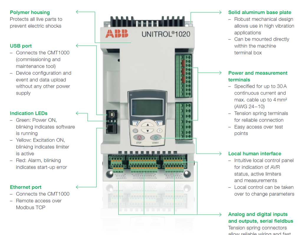
Main functions and features
Control mode: Supports automatic voltage regulator (AVR), excitation current regulator (FCR), power factor regulator (PF), reactive power regulator (VAR), etc., and can achieve disturbance free switching between various modes.
Limiter and protection: including excitation current limiter (minimum/maximum), PQ minimum limiter, motor current limiter, V/Hz limiter, motor voltage limiter, etc., to ensure the safe and stable operation of synchronous motors; It has functions such as soft start, voltage matching, and rotating diode monitoring.
Software Function Package: Provides four versions: ECO, LIGHT, BASIC, and FULL, ranging from basic functions to advanced features such as synchronization, event recording, data recording, and real-time clock. The FULL version can also add a Power System Stabilizer (PSS) option, which complies with the IEEE 421.5-2005 standard.
Communication capability: Supports protocols such as Modbus RTU, Modbus TCP, CAN, etc., equipped with Ethernet and USB ports for easy connection to debugging tools and remote access.
Environmental adaptability: Designed for wide temperature environments and harsh industrial conditions, it can be directly installed on machines and has high EMC immunity.
Debugging and maintenance tools
CMT 1000 is a debugging and maintenance tool for this series, which connects devices via USB or Ethernet. Its functions include:
Set parameters and adjust PID to ensure stable operation;
Comprehensive monitoring system to assist in identifying and locating issues during on-site debugging;
Provide functions such as a main window (displaying access modes and device information), a settings adjustment window (viewing control modes, alarms, etc.), and an oscilloscope (recording and analyzing signals).
application area
Widely used in land-based power plants (based on diesel engines, gas/steam turbines, water turbines), ships (electric propulsion and auxiliary power supply), traction (diesel electric locomotives), wind energy (based on directly connected synchronous motors), synchronous motors, and variable speed applications.
Working principle
Signal acquisition: Real time acquisition of key parameters such as three-phase voltage, current, and grid voltage of the motor through measuring terminals, as a basis for adjustment.
Deviation calculation: Compare the actual voltage of the collected motor with the set target voltage to calculate the deviation value.
Control regulation: Based on the deviation value, the built-in control algorithm (such as PID regulation) is used to generate excitation current regulation commands, and the current size of the excitation system is adjusted through the IGBT power output stage.
Dynamic response: Quickly respond to changes in the power grid or load, adjust the magnetic field strength of the motor by changing the excitation current, and then correct the motor terminal voltage to stabilize it within the set range.
Protection and Limitation: Equipped with multiple limiters (such as excitation current, V/Hz limit, etc.), it automatically intervenes when parameters exceed the safe range to prevent motor overload or damage, ensuring the safe operation of the system.

- User name Member Level Quantity Specification Purchase Date
- Satisfaction :
-


-
 SIGMATEK TAE1941 Display Unit Replacement and Troubleshooting
 -
 SIGMATEK TAE151 Replacement and Troubleshooting
 -
 SIGMATEK AKM Servo Motor Replacement and Troubleshooting Guide
 -
 SIGMATEK S-DIAS Control System Replacement and Upgrade Guide
 -
 SIGMATEK ETT Series HMI Replacement and Selection Guide
 -
 SIGMATEK DIAS Drive 310-23 servo amplifier
 -
 SIGMATEK CCP 521 C-DIAS processor module
 -
 Megmeet L6 electric drive troubleshooting
 -
 Sysmex XN-1000/2000 Technical Guide
 -
 Sysmex XN-L blood analyzer maintenance and troubleshooting
 -
 Troubleshooting and Maintenance of Sysmex XN-9000
 -
 LTI Motion ServoOne PROFIBUS/PROFINET Troubleshooting and Replacement
 -
 Micro Innovation MICRO GF1 Touch Screen Troubleshooting and Replacement
 -
 Troubleshooting and Replacement of Micro Innovation WINbloc Distributed I/O System
 -
 MICRO PANEL GS-2 Troubleshooting and Debugging
 -
 LTi Synchronous Motor LST/LSH Replacement Selection Guide
 -
 Fault diagnosis of LTi CDE/CDB3000
 -
 Maintenance and troubleshooting of ENOTEC SILOTEC 8000 silo analyzer
 -
 ENOTEC ENSITU 7000 Oxygen Analyzer
 -
 ENOTEC COMTEC 6000 ATEX GasEx Analyzer Maintenance, Calibration, and Troubleshooting Guide
 -
 ENOTEC Analyzer Family Selection Guide
 -
 ENOTEC OXITEC 500E Oxygen Analyzer
 -
 KUKA KR CS Box-2 Compact Controller for Four Axis SCARA Robot
 -
 KUKA KR C5 slim-2 Robot Controller
 -
 KUKA KR C5 micro KSS troubleshooting
 -
 KUKA KR C5 micro debugging and troubleshooting
 -
 KUKA KR C5 Controller Assembly and Troubleshooting
 -
 KUKA KR C5 Cabinet Assembly and Troubleshooting
 -
 KUKA KR C4 Smallsize-2 Debugging Guide
 -
 KUKA KR C4 Midsize Assembly Guide
 -
 ENOTEC OXITEC 5000 Oxygen Analyzer Maintenance Guide
 -
 KUKA KR C4 extended assembly and debugging
 -
 KUKA KR C4 compact assembly and debugging
 -
 KUKA Sunrise Cabinet Med Medical Collaborative Robot Special Control Cabinet
 -
 KUKA Sunrise Cabinet Next Generation Small Control Cabinet
 -
 KUKA KR C4 Smallsize-2 family's smallest control cabinet
 -
 KUKA KR C4 Midsize Fault Diagnosis
 -
 KUKA KR C4 extended is a high-power multi axis control cabinet
 -
 Troubleshooting and Maintenance of KUKA KR C4 Control Cabinet
 -
 Troubleshooting and Maintenance of KUKA KR C4 Compact Control Cabinet
 -
 KUKA KR15 DELTA-2 V2 Robot Installation and Debugging
 -
 KUKA TITAN-2 Ultra Assembly and Maintenance Guide
 -
 KUKA KR SCARA-2 CS Assembly, Debugging, and Operation Guide
 -
 Troubleshooting KUKA SCARA X
 -
 Troubleshooting of KUKA KR FORTEC-2 ultra
 -
 Troubleshooting of KUKA KR FORTEC-2
 -
 Troubleshooting KUKA KR 1000 Titan
 -
 Troubleshooting of KUKA KR 600 FORTEC
 -
 KUKA KR 500 MT FORTEC Maintenance and Inspection
 -
 KUKA KR 360 FORTEC Inspection and Maintenance Guide
 -
 Troubleshooting KUKA Sunrise Cabinet Med
 -
 KUKA KR SCARA HO Assembly and Maintenance
 -
 KUKA QUANTEC-2 PA maintenance troubleshooting
 -
 KUKA QUANTEC-2 K/P Maintenance Troubleshooting Guide
 -
 KUKA QUANTEC-2 HO Maintenance Guide
 -
 KUKA KR QUANTEC-2 HC Maintenance and Rescue Guide
 -
 KUKA KR QUANTEC-2 Maintenance Troubleshooting Guide
 -
 KUKA KR QUANTEC PA series heavy-duty palletizing robot
 -
 KUKA KR IONTEC-2 Debugging and Maintenance Guide
 -
 KUKA KR IONTEC ultra series six axis heavy-duty industrial robot
 -
 KUKA KR IONTEC HO Maintenance Troubleshooting Guide
 -
 KUKA KR CYBERTECH-3 HW maintenance troubleshooting
 -
 KUKA KR CYBERTECH-3 maintenance troubleshooting
 -
 KUKA KR8 R2100-2 arc HW maintenance troubleshooting
 -
 KUKA KR CYBERTECH nano-2 maintenance troubleshooting
 -
 KUKA KR 20 R1810 HO maintenance troubleshooting
 -
 KUKA CYBERTECH maintenance troubleshooting
 -
 KUKA KR CYBERTECH CR maintenance troubleshooting
 -
 KUKA KR AGILUS-3 ultra maintenance troubleshooting
 -
 KUKA KR 300 R2700-2 C-F maintenance troubleshooting
 -
 KUKA KR 20 R1820-2 E Maintenance Troubleshooting and Replacement Practice
 -
 KUKA AGILUS-3 troubleshooting
 -
 KUKA KR AGILUS-2 maintenance troubleshooting
 -
 KUKA KR 1000 titan PA troubleshooting
 -
 KUKA KR 700 PA maintenance troubleshooting
 -
 KUKA KR18 R1450-3 PP Operation and Maintenance Essentials
 -
KUKA KR12 SCARA Operations Essentials
-
 KUKA KR4 R600 Operation and Maintenance Essentials
 -
 KUKA KR 3 AGILUS Operation and Maintenance Safety Essentials
 -
 KUKA LBR iiwa CR Cleanroom Troubleshooting and Maintenance
 -
 Troubleshooting and Maintenance of KUKA KR AGILUS sixx
 -
 KUKA KR60 SCARA CS Maintenance Guide
 -
 KUKA KR 23 SCARA-2 Robot Installation and Maintenance Detailed Explanation
 -
 KUKA KR 20 SCARA CS Robot Selection and Maintenance Guide
 -
 KUKA KR 15 DELTA-2 Robot Installation and Maintenance
 -
 KUKA KR 13 SCARA-2 CS Detailed Explanation
 -
 KUKA KR 3 D1200 Robot Operation and Maintenance
 -
 KUKA KR 3 D1200 HM Robot Operation and Maintenance Guide
 -
 KUKA LBR Med Medical Robot Integration Guide
 -
 KUKA iiwa Robot Safety Operation and Maintenance
 -
 KUKA LBR iiwa CR Operations and Troubleshooting
 -
 Lauer PCS Series Operation Console Configuration Guide
 -
 Installation and Maintenance Guide for KUKA LBR iisy Series Collaborative Robots
 -
 KUKA LBR iisy 3 R760 Collaborative Robot Debugging Guide
 -
 KUKA LBR iico Robot Installation and Debugging Technical Guide
 -
 Lauer Starline LCA 300/320/325 Text Display Application Guide
 -
 Lauer PCS 950 Operation Console Application Guide
 -
 Lauer EPC series industrial computer configuration
 -
 Bonfiglioli Precision Planetary Gearbox Selection and Application Guide
 -
 Installation and heat dissipation of Bonfiglioli Vectron cold plate frequency converter
 -
 Bonfiglioli Vectron EM-RES-02 Expansion Module Installation and Configuration Guide
 -
 Bonfiglioli Vectron EM-RES-01 Expansion Module Rotary Transformer Interface Configuration Guide
 -
 Bonfiglioli Vectron EM-IO-04 module KTY temperature measurement and digital port configuration
 -
 Bonfiglioli Vectron EM-IO-03 Expansion Module Dual Analog Output and PTC Configuration
 -
 Installation of Bonfiglioli Vectron EM-IO-02 Expansion Module and PTC Temperature Monitoring Configuration
 -
 Bonfiglioli Vectron EM-IO-01 Expansion Module Installation and System Bus Configuration Guide
 -
 Bonfiglioli F series gearbox spare parts identification and replacement guide
 -
 Installation, maintenance, and troubleshooting of Bonfiglioli HF series reducers for hoisting applications
 -
 Bonfiglioli 300 series reducer installation, maintenance, and troubleshooting guide
 -
 Selection and integration guide for Bonfiglioli R3 series planetary gearboxes in primary crushing equipment
 -
 Bonfiglioli C-series ATEX gearbox selection and explosion-proof application guide
 -
 Bonfiglioli Vectron EM-ENC-05 Full Function Expansion Module Integration Guide
 -
 Bonfiglioli Vectron EM-ENC-04 Multi functional Expansion Module Complete Configuration Guide
 -
 Bonfiglioli Vectron EM-ENC-03 Second Encoder Interface and System Bus Expansion Guide
 -
 Bonfiglioli Vectron EM-ENC-02 Expansion Module Integration and Encoder Interface Guide
 -
 Bonfiglioli Vectron CM-CAN CANopen Communication Configuration and DS402 Control Guide
 -
 Bonfiglioli Vectron EM-SYS System Bus Networking and Virtual Link Configuration Guide
 -
 Bonfiglioli Vectron CM-PDP Profibus DP Configuration and Debugging Guide
 -
 Bonfiglioli Vectron CM-232/485 Modbus Communication Configuration Guide
 -
 Bonfiglioli BMS series servo reduction motor selection and integration guide
 -
 Bonfiglioli ACTION 210/410 Inverter Debugging and Fault Diagnosis Complete Guide
 -
 Honeywell Enhanced Micro TDC 3000X System Redundancy Architecture and Maintenance Guide
 -
 Selection and Configuration of Bonfiglioli Active Series Inverter
 -
 Installation, Maintenance, and Troubleshooting Guide for Bonfiglioli HDP/HDO Series Heavy duty Gearboxes
 -
 Installation, Maintenance, and Troubleshooting Guide for Bonfiglioli 300/300M Series Gearboxes
 -
 Bonfiglioli 300M planetary gearbox selection and thermal verification guide
 -
 Bonfiglioli 3/H series heavy-duty gearbox selection and verification guide
 -
 Bonfiglioli KRG/KCG/KSD Hydraulic Coupling Selection and Integration Guide


