
Allen Bradley 1203-CN1 ControlNet Communication Module
Allen Bradley 1203-CN1 ControlNet Communication Module
Product Overview and Core Positioning
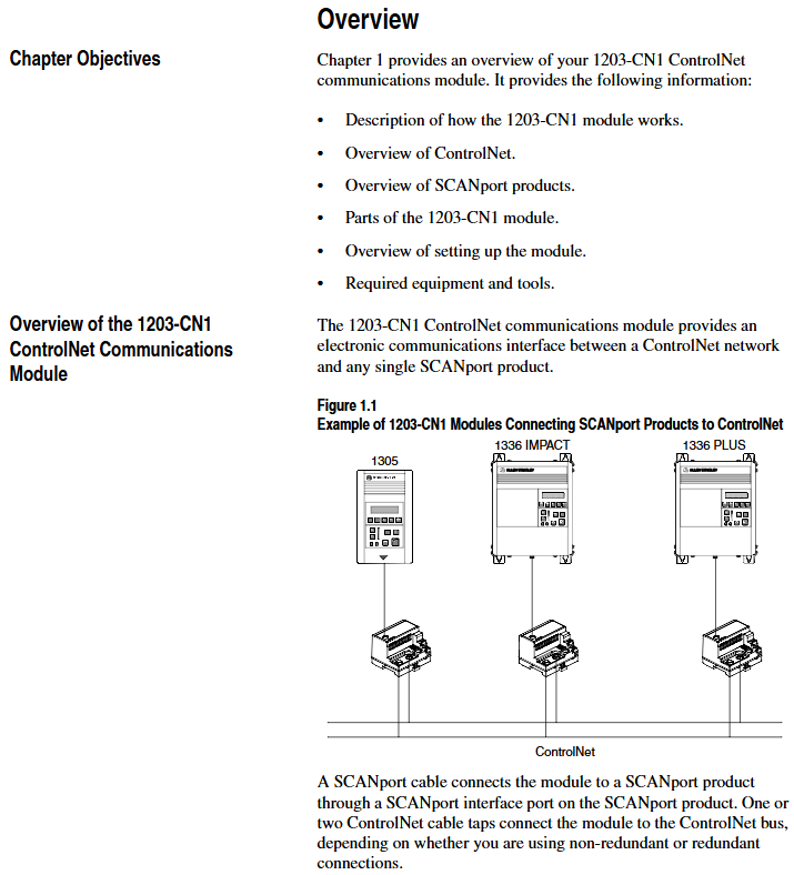
Product Function: As a bridge between the ControlNet network and SCAnport products, the module can convert ControlNet messages into signals recognizable by SCAnport products, supporting the transmission of scheduled I/O data (such as logical instructions, analog reference values) and non scheduled messages (such as parameter read/write, fault query). The ControlNet network speed reaches 5Mbps, ensuring real-time and deterministic performance.
Adaptation scenarios: Compatible with various Allen Bradley SCANPort products, including 1305 AC micro drives, 1336 series inverters (IMPACT/PLUS/FORCE), 1394 multi axis motion control systems, SMC Dialog Plus controllers, etc. Different products support 1-6 peripheral connections, with an I/O word length range of 0-10 words (depending on the product model).
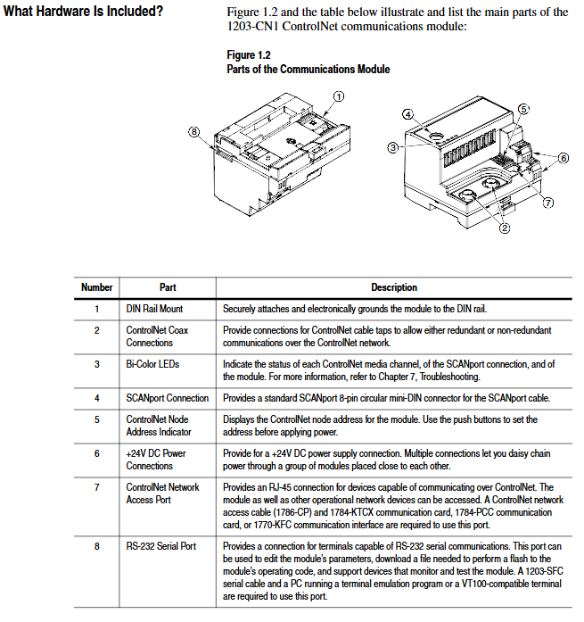
Hardware composition: The core hardware interfaces and components of the module are shown in the table below:
|Component Name | Function Description|
|DIN rail mounting seat | Fixed module and electrically grounded, compatible with 35 × 7.5mm DIN rails (models 199-DR1, etc.)|
|ControlNet coaxial interface (A/B channels) | Connect ControlNet cable taps, supporting redundant/non redundant network configurations|
|Two color LED indicator lights | 4 status lights (ControlNet A/B channels SCANport、 The module itself is used for fault diagnosis|
|SCANPort interface | 8-pin circular mini DIN connector, connected to SCANPort products through a dedicated SCANPort cable|
|ControlNet Node Address Indicator | Press the key to set the node address (0-99), which needs to be powered off and restarted to take effect, ensuring that the address is unique within the network|
|24V DC power interface | Supports multi module Daisy chain power supply, reduces wiring complexity|
|Network Access Port (RJ-45) | To connect ControlNet network devices, a 1786-CP cable and a 1784-KTCX communication card are required|
|RS-232 serial port | Used for parameter configuration and firmware upgrade, requires 1203-SFC serial port cable and terminal simulation software/VT100 terminal|
Installation and electrostatic protection
1. Installation preparation
Tools and equipment: Grounding wristband (included with module), 1/8 inch flathead screwdriver, blunt tool (set node address), ohmmeter, SCANPort cable (such as 1202-C03/C10, up to 10m), ControlNet tap (such as 1786-TPS/TPR, redundant configuration requires 2).
Static protection: The module contains ESD sensitive components, and a grounding wristband must be worn during operation. Refer to Allen Bradley document 8000-4.5.2 "Guidelines for Preventing Static Damage".
2. Installation steps
Set node address: Use a blunt tool to press the "+/-" keys to set a unique address (0-99). It needs to be powered off and restarted to take effect. Avoid using pencils/pens to prevent damage to the switch.
Rail installation: Insert the top hook of the module into the DIN rail, rotate and fasten it, and use an ohmmeter to check the rail grounding (the resistance between the metal shell of the RS-232 port of the module and the rail grounding is ≤ 2 Ω).
Cable connection: Insert the SCANPort cable alignment interface (hear a snap sound); Screw the ControlNet tap into the corresponding A/B channel; 24V DC power supply connection (supports multi module cascade power supply).
Installation verification: After power on, the SCANPort and ControlNet LEDs remain constantly green, and the module LED flashes green (when network configuration is not completed). If the LED status is abnormal, the wiring needs to be checked.
3. Module removal
After power failure, disconnect all cables (SCANPort cables need to be pressed and pulled out), pry the release buckle with a screwdriver, remove the module, and maintain grounding protection throughout the process.
Basic configuration and operation
1. Serial port connection and parameter configuration
(1) Connection preparation
Hardware: 1203-SFC serial port cable (connecting module RS-232 port to PC/terminal).
Software: PC needs to install terminal simulation software (such as Windows HyperTerminal) or use VT100 compatible terminals.
(2) Serial port configuration steps
Software settings: default baud rate of 9600 (parameter 21 can be modified, supports 2400/4800/19.2K/38.4K), data bit 8, no checksum, stop bit 1, no flow control; Simulate to select VT100 mode.
Access main menu: Press Enter to enter the module main menu, supporting 7 functions:
1: Display/edit parameters; 2: Specify parameter number for query; 3: Display event queue; 4: Display current I/O data; 5: Display DF1 protocol statistics; 6: View serial number; 7: Firmware upgrade.
(3) Key parameter configuration
The default parameters of the module support 16 bit logic instructions/status and 16 bit reference/feedback values. When the SCANPort product triggers a fault in PLC programming mode or network failure, the following parameters can be used to adjust the function:
Parameter Number Name Function Description Default Value
4 CMD/Stat enable/disable logical instructions from ControlNet to SCAnport/simulate reference data transfer 1 (enable)
5-8 DataLnk A-D Config Enable/Disable corresponding data link (each channel occupies 2 inputs+2 output words) 0 (disabled)
9-10 Idle/Comm Flt Action PLC programming mode/action in case of network failure (0=fault, 1=zero data, 2=hold last value, 3=fault configuration value) 0 (fault)
11-20 Fault Cfg Logic/Ref/A1-D2 In: The preset values (logic instructions, reference values, data link values) outputted during a fault are 0
21 Serial Port Rate (0=2400, 1=4800, 2=9600, 3=19.2K, 4=38.4K) 2 (9600)
22 Reset Adapter Reset Module (1=Reset, 2=Reset after restoring default parameters) 0 (Ready)
2. Firmware Upgrade (Flash Upgrade)
Prepare the upgrade file (such as cn1-0_61.bin), connect via serial port to enter the main menu, and select "7>Update Flash Program".
Confirm that the SCANPort product is in a safe state (the product will malfunction and shut down during the upgrade), and press Y to start the upgrade.
Select "Send File" from the "Transfer" menu in the terminal software, choose Xmodem for the protocol, and select "Upgrade File Send". The entire process cannot be interrupted, and the module will automatically restart after completion.
ControlNet Network Configuration
1. Configuration tools and prerequisites
Software: RSNetWorx for ControlNet (32-bit Windows application), RSLinx (communication interface).
Hardware: The PC needs to be connected to the ControlNet network through a 1784-KTCX/1784-PCC card or 1770-KFC adapter.
2. Network configuration steps
Enter online mode: Start RSNetWorx, click "Online", automatically scan the network through RSLinx, and select the target ControlNet network.
Module Mapping:
Click on 'Edits Enabled', right-click on the controller (such as PLC-5) and select 'ControlNet Configuration'.
Select the node (module node address) corresponding to the SCANPort product, insert "Device Connection", and configure the unique N-file address for diagnostic/status/data input/output files.
Set input/output size (control I/O enable+2 words, each data link+2 words, range 2-10 words), RPI (request packet interval) ≥ network update time (NUT).
Save and Verify: Save the configuration file and download it to the controller. Set NUT ≥ 5ms, Max Scheduled Address ≥ highest I/O node address, and Max Unscheduled Address ≥ highest network node address in the network properties.
Configuration confirmation: The SCANPort product icon in RSNetWorx displays a gray flag, and the ControlNet LED of the controller and module is constantly green, indicating normal communication.
PLC programming and message communication
1. Ladder diagram programming (RSLogix5)
Implement I/O interaction between the controller and SCANPort product through N-file mapping. Example functions include start stop control, fault clearing, and frequency reference value transmission. Please note:
Logical instruction bit definition: For example, in the 1336 PLUS driver, bit 0=stop, bit 1=start, bit 2=jog, and bit 3=fault clearing. Please refer to the SCANPort product manual for details.
Data scaling: For example, the frequency reference value 0-32767 of the 1305 driver corresponds to 0-maximum frequency, which needs to be transmitted through MOV instructions in the program (such as N7:0 → N13:1).
2. Message communication (PCCC and analog block transmission)
(1) PCCC message
Support PLC-5 Typed Read/Write and encapsulate protocol messages, examples include:
Read 10 SCANPort product parameters (starting parameter 1): target address N10:1, PLC data storage N20:0, Size=10.
Read the complete information of a single parameter (such as parameter 1): target address N30:1, size=20 (including parameter name, unit, maximum value, etc.).
(2) Simulated Block Transfer
Supports 11 types of commands such as parameter read/write, fault queue query, NVS storage operation, etc., which need to be implemented through 2 MSG instructions (write request first, then read response). Examples include:
Parameter value reading: Request instruction length of 3 words (message length 3, decimal 769, parameter number), respond with parameter value or error code.
Fault queue reading: Request to specify queue number, respond with fault text (displayed in reverse ASCII), fault code, and timestamp (supported by 1336 FORCE).
Troubleshooting and LED diagnosis
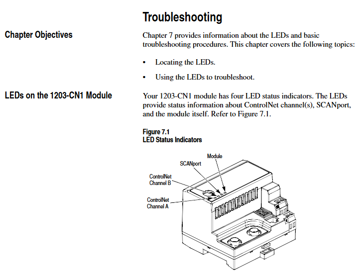
1. Interpretation of LED status
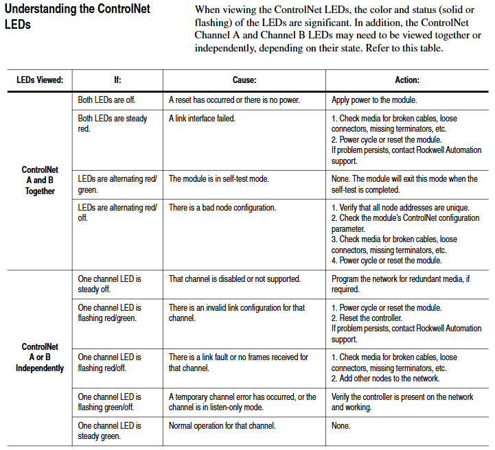
The colors and flashing patterns of the four LEDs in the module correspond to different states. The core troubleshooting is as follows:
Solution for LED type status reasons
Check the cable/tap for faults in the red link interface of both ControlNet A/B. Power off and restart, if ineffective, contact after-sales service
SCANPort flashing red SCANPort communication error/data link does not support reconnecting cables, verify module compatibility with product configuration
Module flashing red (3 times) Non volatile storage CRC error check parameters, modify and save at least 1 parameter, then restart
Module flashing green configured I/O but no ControlNet connection confirmed controller network configuration, remap module
2. Event queue and DF1 statistics
Event queue: Select "3>Display event queue" from the main menu to view fault/warning information (graded by severity: I=information, W=warning, S=serious, F=fatal), which can be cleared through "Clr Event Queue".
DF1 statistics: View the number of sent/received packets, undelivered messages, NAK errors, etc., and reset the statistics through "Clear DF1 Counts".
Core specifications
Project parameters
Power supply 24V DC (-20%~+30%), maximum current 250mA
Working environment temperature 0~60 ° C, humidity 5%~95%, no condensation, vibration 2.5g (5Hz~2KHz), impact 30g (working)/50g (non working)
Protection level UL 508/CUL, 6KV contact discharge/8KV air discharge, metal shell required to achieve EMC Class A compliance
- OMRON
- ABB
- General Electric
- EMERSON
- Honeywell
- HIMA
- ALSTOM
- Rolls-Royce
- MOTOROLA
- Rockwell
- Siemens
- Woodward
- YOKOGAWA
- FOXBORO
- KOLLMORGEN
- MOOG
- KB
- YAMAHA
- BENDER
- TEKTRONIX
- Westinghouse
- AMAT
- AB
- XYCOM
- Yaskawa
- B&R
- Schneider
- KONGSBERG
- NI
- WATLOW
- ProSoft
- SEW
- ADVANCED
- Reliance
- TRICONEX
- METSO
- MAN
- Advantest
- STUDER
- DANAHER MOTION
- Bently
- Galil
- EATON
- MOLEX
- DEIF
- B&W
- ZYGO
- Aerotech
- DANFOSS
- Beijer
- Moxa
- Rexroth
- Johnson
- WAGO
- TOSHIBA
- BMCM
- SMC
- HITACHI
- HIRSCHMANN
- Application field
- XP POWER
- CTI
- TRICON
- STOBER
- Thinklogical
- Horner Automation
- Meggitt
- Fanuc
- Baldor
- SHINKAWA
- Other Brands
- UniOP
- KUKA
- Iba
- Beckhoff
-
 Basler Electric BE1-87G Differential Relay
 -
 Basler Electric BE1-11 Protection System I5A3M2P2N0EA00
 -
 Basler Electric DECS-200-1C Excitation Control System
 -
 Basler Electric BE1-11g Generator Protection Relay
 -
 Basler Electric DECS 125-15-B2C1 V2.0.9 Excitation Control
 -
 Basler Electric BE1-81O/UT3ED1JA7N2F Frequency Relay
 -
 Basler Electric BE1-81O/UT3EE1YB7N1F Frequency Relay
 -
 Basler Electric DECS-200-1L Digital Excitation Control System
 -
 Basler DECS125-15-B2C1 Excitation Control
 -
 Basler 9507900205 SSR Retrofit Voltage Regulator
 -
 Basler BE2000E Digital Voltage Regulator
 -
 Basler BE1-GPS Generator Protection System
 -
 Basler DECS-250-CN1CN1N Digital Excitation Control
 -
 Basler DGC-2020 Genset Controller
 -
 Basler BE1-81O UT3ED1LA7N0F Frequency Relay (Variant)
 -
 Basler BE1-81O UT3EE1YA9S0F Frequency Relay (Variant)
 -
Basler BE1-81O Over/Under Frequency Relay
-
 Basler DECS125-15 Digital Excitation Control
 -
 Basler Electric BE1-951 Overcurrent Protection System
 -
 Basler Electric BE1-700V Digital Protective Relay
 -
 Basler Electric APR63-5 Automatic Voltage Regulator
 -
 Basler Electric BE1-851 Overcurrent Protection System
 -
Basler Electric DECS-250-LN1SN1N Excitation Control
-
 Basler Electric BE1-87T Transformer Differential Relay
 -
 Basler Electric DECS-200-1L Excitation Control System
 -
 Basler Electric 9310300100 DECS-300 Excitation Control
 -
 Basler Electric SSE-N 125-4.5KW Shunt Exciter Regulator
 -
 Basler Electric DGC-2020HD-5NS1DNSBA Genset Controller
 -
Basler Electric BE1-81-O/UT3EE1JB7N1F Frequency Relay
-
Basler Electric BE1-81T1EE1WA0N1F Frequency Relay
-
 Basler Electric BE1-25M1EA6PN5R1F Sync-Check Relay
 -
 Basler Electric BE1-GPS Generator Protection System
 -
Basler Electric DECS-250-LN1SN1N Excitation Control Rev V
-
 Basler Electric DECS-250-CN2CN1N Excitation Control
 -
 Basler Electric BE1-50/51B-207 Overcurrent Relay
 -
Basler Electric DECS-300-C0N0 Excitation Control System
-
Basler Electric DECS-200 Digital Excitation Control System
-
Basler Electric DECS-250-LN1CN1N Excitation Unit
-
Basler Electric DECS-250 LN2SA1D Excitation Unit Specs
-
Basler Electric BE1-87T Transformer Relay Review
-
Basler Electric BE1-11 Protection System
-
Basler Electric BE1-GPS100-E4N1H1N Protection System
-
 Allen-Bradley 442G-MABH-R Safety Module
 -
 Beckhoff CX1030-0111 PLC Assembly Profile
 -
 FANUC IC693CPU364 PLC Module
 -
 Orange Denmark Type 200816 220 PLC Specs
 -
 OMRON C200H-SNT31 Sysmac PLC Module
 -
 Allen Bradley 20AB022A3AYNANC0 PowerFlex 70
 -
 OMRON C200HW-PCU01 Position Control Unit
 -
 ABB AO845A-eA Analog Output Module
 -
 OMRON CJ1M-CPU22 CPU Unit
 -
 Allen Bradley 100-E265ED11 Contactor
 -
 Honeywell 51304511-100 Interface Module
 -
 SOLEXY BXF3S0101N0018 Gateway Module
 -
 OMRON CJ2H-CPU65 CPU Unit
 -
 Automation Direct GS2-45P0 AC Drive
 -
 M68-2000 2-Axis Motion CNC Controller
 -
 OMRON CJ1M-CPU11 V3.0 PLC CPU Unit
 -
 OMRON CJ1W-NC413 4-Axis Positioning Controller
 -
 OMRON 3G2A3-PRO16 Programming Console HMI
 -
 Siemens 3VT8440-2AA04-2GA2 Molded Case Circuit Breaker
 -
 Siemens 3RT5045 Contactor Series
 -
 OMRON C200HS-CPU01-E SYSMAC PLC Controller
 -
 OMRON C500-NC103-E Positioning Control Unit
 -
 OMRON CJ1W-TC001 Temperature Control Unit
 -
 OMRON NJ301-1100 NJ-PA3001 PLC System EtherCAT
 -
 Pilz 773100 M1P Safety Relay Base Unit
 -
 Siemens SINUMERIK 840D SL NCU 720.3B with PLC 317-3 PN/DP
 -
 Siemens 6AV6618-7GD01-3AB0 HMI Panel
 -
 OMRON F150-C15E-3 Vision Mate Controller PLC Overview
 -
 Mitsubishi MELSEC A Series PLC System A63P A3ACPU A616AD A68RD3
 -
 M68-2000 2 Axis Motion Controller SCE SERVO CNC
 -
 OMRON FZ-S2M PLC Camera Vision System
 -
 VISOLUX SLVA-4K PLC Module from Elektronik GmbH
 -
 OMRON CJ1M-CPU23 V2.0 PLC CPU Unit
 -
 ABB AI86-16CHF PCB Card 5761751-9 B Specifications
 -
 Allen-Bradley 100-D140ZJ22L Contactor Overview
 -
 Merlin Gerin PB80 PLC Rack
 -
 WEIR WE203 Power Supply PLC
 -
 OMRON NX-TS3102 Temperature Input Unit
 -
 Siemens 6ES7146-6FF00-0AB0 I/O Module
 -
 Fanuc A16B-3300-0057 Circuit Board
 -
 OMRON CJ1W-IDP01 Input Module
 -
 Siemens 6FX2007-1AD13 Handheld Unit
 -
 Gems EM54 PLC Module PCB
 -
 Beckhoff CX2030-0121 Embedded PC CPU
 -
 OMRON NJ301-1100 Machine Automation Controller
 -
 Biesse Rover CNI PLC 2153 030 7146.30 Numerical Control Module
 -
 OMRON CJ1W DA08V Analog Output Module
 -
 OMRON CS1D ETN21D Ethernet Module
 -
 Allen Bradley 1768 L43 CompactLogix Controller
 -
 Schneider TWDLMDA40DTK Twido PLC Module
 -
 Mitsubishi NZ2EX2B 60AD4 Analog Input Module
 -
 OMRON NS8 TV00B V2 Touch Display Panel
 -
 Mitsubishi AY71 CMOS TTL Output Module
 -
 OMRON C500 CPU11 E Processor Module
 -
 OMRON CJ1W PTS51 Temperature Input Module
 -
 Siemens 6SL3100-1DE22-0AA1 600V DC Supply
 -
 OMRON CJ1M-CPU23 PLC CPU 9‑Pin Serial
 -
 Schlumberger IMT4N 24‑250VAC 48‑230VAC PLC Timer
 -
 OMRON CJ1M-CPU22 PLC CPU Unit V2.0
 -
 Allen‑Bradley 2711P-B7C6D2 Touch Screen PanelView
 -
 ADSP-2181KST-160 Analog Devices DSP IC Specs
 -
 Schneider LC1F400 400A Contactor Specifications
 -
 Yaskawa SGDH-10DE-OY 1kW 400V Servo Drive
 -
 Schneider TM262L10MESE8T M262 PLC 5ns Inst
 -
 Mitsubishi AA104VJ05 10.4in LCD Panel Specs
 -
 Allen Bradley 1761-L32BWA MicroLogix 1000 PLC
 -
 Siemens 6ES7431-7KF00-0AB0 Analog Input Module
 -
 Allen Bradley 1769-OB16 Output Module
 -
 Siemens 6ES7131-1BL12-0XB0 Input Module
 -
 Beckhoff EP7041-3002 EtherCAT Box Module
 -
 Siemens RK7243-2AA30-0XB0 Communication Module
 -
 Siemens 4AM5742-8DD40-0FA0 Transformer
 -
 Siemens 3TK2834-1BB40 Safety Relay
 -
 Brother BAS 311 Sewing Machine Circuit Board
 -
Yaskawa SGDH-10DE-OY Servo Driver
-
 OMRON C60H C6DR DE V1 Sysmac PLC
 -
 MITSUBISHI ELECTRIC A2ACPU21 S1 CPU Module
 -
 ABB BAILEY INNPM12 Network Process Module
 -
 HONEYWELL 620 0073C IPC PLC Module
 -
 Mitsubishi 15050 PR02B PLC Circuit Board
 -
 SIEMENS 6SY7000 0AC37 Drive Control Module
 -
 OMRON TJ2 ECT16 Traxial EtherCAT Controller
 -
 GE Fanuc IC698PSD300D Power Supply Module
 -
 Texas Instruments Series 505 16 Position Base
 -
 OMRON YASKAWA SGDH 10DE OY Servo Drive
 -
 Allen‑Bradley 440G-MT Safety Interlock Switch Specs


