
Allen Bradley 1326AB high-performance AC servo motor
Allen Bradley 1326AB high-performance AC servo motor
Product Overview and Core Positioning
1. Product type and applicable scenarios
The 1326AB series is a three-phase brushless permanent magnet synchronous servo motor designed for high-precision motion control, compatible with Allen Bradley 1391 AC servo controller. It is widely used in machine tools, automated production lines, material handling and other scenarios that require precise positioning and high-speed response. It supports various mechanical structures such as screw drive, gear rack drive, conveyor belt drive, etc.
2. Core standard features
Performance Design:
Permanent magnet rotor structure improves servo response speed; Sine wave winding stator achieves low-speed smooth operation and efficient heat dissipation.
100% continuous rated locked rotor torque at zero speed, meeting the requirements for maintaining static load.
Feedback system:
Standard brushless rotary transformer, providing position, commutation, and speed feedback, without built-in electronic components, suitable for harsh environments.
Supports 1391 A Quad B encoder output (up to 2048 PPR), achieving high-precision position detection through rotary transformer signal conversion.
Protection and reliability:
TENV (fully enclosed non ventilated) structure, optional shaft seal kit (1326AB-MOD-SSV-xx) can achieve IP65 protection level (dustproof, anti pulsating water flow), but IP65 fails when external encoder/rotary transformer or fan is connected.
The winding is equipped with a normally closed thermal switch (115V AC/1A, 24V DC/1A) to achieve overheating protection, with a trigger temperature of about 150 ° C and a reset temperature of 90-100 ° C.
Installation and compatibility:
Supporting vertical/horizontal axis installation, the rotor dynamic balance accuracy reaches 0.0005 inches (0.0127mm) peak to peak displacement, reducing operational vibration.
Equipped with MIL standard connectors, the power and feedback cables support standard flexibility, high flexibility of drag chains (- T suffix), and ultra long (ES suffix, up to 300 feet/91.4m) versions, adapting to different installation distance requirements.
Model interpretation and optional configurations
1. Model coding rules (taking 1326AB-A1G-11-A4 as an example)
Explanation of the meaning of digit codes
1-4 Position 1326 Product Series AC Servo Motor
5th motor type A AC permanent magnet synchronous
6th B frame diameter A=4.25 inches (108mm), B=5.88 inches (149mm), C=7.63 inches (194mm)
The 7th position A is distinguished in alphabetical order based on the stacking length within the same framework (A<B<C<D, with increasing length and greater torque)
8th highest speed G=5000rpm, E=3000rpm, C=2000rpm, B=1600rpm
Installation of positions 9-10 and shaft type 11=NEMA British flange+keyway shaft; 21=IEC metric flange+metric shaft
The 11th to 12th positions of A4 can be selected with attachment A series=90V DC brake (A4=72 lb in/8.1N · m, A5=120 lb in/13.6N · m, A7=400 lb in/45.2N · m); K series=24V DC holding brake (K4/K5/K7 correspond to the same torque)
2. Key optional configurations
Configuration Type Model/Option Code Function Description
The 1326-MOD-BPS brake power supply converts 115V AC to 90V DC and is compatible with A-series brakes. A single unit can drive 4 brakes
Shaft seal kit 1326AB-MOD-SSV-xx on-site installation of Viton material shaft seal, no need to disassemble the motor, compatible with A/B/C series
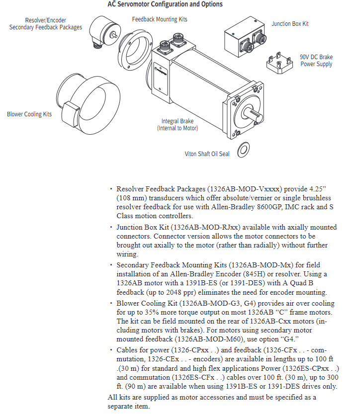
Feedback component 1326AB-MOD-Vxxxx 4.25-inch (108mm) rotary transformer, supports absolute/fine adjustment format, compatible with 8600GP, IMC and other controllers
Junction box 1326AB-MOD-RJxx axial lead out connector (replacing radial default), maintaining IP65 protection, compatible with A/B/C series
Fan cooling 1326AB-MOD-G3/G4 G3=C2E/C4B motor rear fan; G4=C4B motor "saddle shaped" fan, increasing torque output by 35%
Cable 1326 CPxx (power supply), 1326 CFx (commutation) standard length 15-100 feet, ES version up to 300 feet, only compatible with 1391B-ES/DES driver
Performance parameters and characteristic curves
1. Core performance parameters (typical model examples)
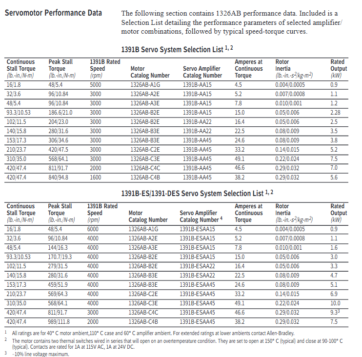
Motor model: Continuous locked rotor torque (lb in/N · m), peak locked rotor torque (lb in/N · m), rated speed (rpm), rotor moment of inertia (lb in s ²/kg-m ²), rated power (kW), continuous current (A)
1326AB-A1G 16/1.8 48/5.4 5000(1391B)/6000(ES/DES) 0.004/0.0005 0.9 4.5
1326AB-B2E 102/11.5 204/23.0(1391B)/279/31.5(ES/DES) 3000(1391B)/4000(ES/DES) 0.05/0.006 2.5 16.4
1326AB-C3E 310/35.0 568/64.1 3000(1391B)/4000(ES/DES) 0.22/0.024 7.5 49.1
1326AB-C4B 420/47.5 840/94.8(1391B)/989/111.8(ES/DES) 1600(1391B)/2000(ES/DES) 0.29/0.032 5.6 38.2
2. Interpretation of speed torque curve
Curve type: divided into two curves: 1391B controller (regular mode) and 1391B-ES/DES (enhanced mode). The peak torque of the former is twice the continuous torque, while the latter can reach three times, and the highest speed is increased (such as A1G from 5000rpm to 6000rpm).
Operating area:
Rated operating zone: Both the motor and controller shall not exceed the RMS rated value, meeting the continuous operation requirements. The calculation formula is:
Torque (T pa=peak acceleration torque, T ss=steady-state torque, T pd=peak deceleration torque, T r=static torque)
Intermittent operation zone: suitable for acceleration and deceleration scenarios, with a duty cycle RMS torque ≤ rated torque to avoid overheating.
Installation and Dimensional Specifications
1. Mechanical installation requirements
Rail adaptation: The A/B/C series both support 35 × 7.5mm DIN rails (models 199-DR1, etc.). The top hook of the module is locked by rotation after being hooked in, and the grounding resistance should be ≤ 2 Ω (detected through the metal shell of the RS-232 port).
Axial load limit: Radial and axial loads must meet the bearing life requirements (B10 life of 15000 hours). Taking the C series as an example, the maximum radial load at 500rpm is 900lbs, and the axial load is 600lbs (refer to the load curve in Figure 8 for details).
2. Key dimensions (taking imperial flanges as an example)
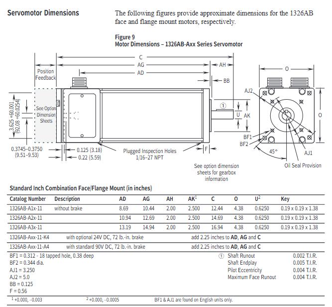
Series length AD (inches) flange diameter O (inches) shaft diameter U (inches) keyway size (inches) with brake length increase (inches)
A1x-11 8.69 4.38 0.625 0.19×0.19×1.38 2.25
B2x-11 13.16 5.88 1.125 0.25×0.25×1.50 2.25
C3x-11 17.38 7.63 1.375 0.31×0.31×2.00 2.5
3. Cable installation
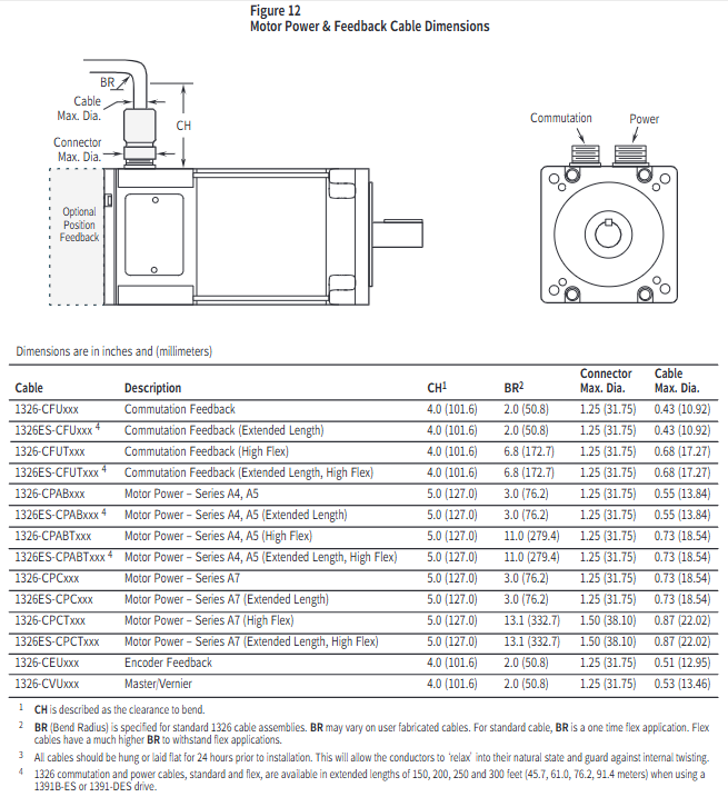
Wiring specifications: Power cables (1326-CPABxx) are wired by color (red=PWR, white=CAN_S, blue=CAN_L, black=COM, bare wire=shielded); The feedback cable (1326 CFUxx) needs to distinguish between the switching signal and the encoder signal, and the shielding layer should be grounded separately.
Bending radius: The standard cable has a single bending radius of ≥ 2 inches (50.8mm), and the high flexibility drag chain cable has a bending radius of ≥ 6.8 inches (172.7mm). Before installation, it needs to be laid flat for 24 hours to release internal stress.
Application Selection and Calculation Guide
1. Selection steps
Determine the speed requirement: Calculate the peak speed of the motor based on the mechanical transmission ratio (for example, if the lead screw is 2 inches and the slide table speed is 400ipm, then the motor speed=400/2=200rpm, with a 20% margin to be reserved).
Calculate continuous torque: Taking screw drive as an example based on load type (friction, cutting force, etc.):
T m=6.28 × e 1 × e 2 × G.R. (W 1 × u+Trust) × Lead × 1.1 (W 1=slide weight, u=friction coefficient, Lead=lead screw, e 1/e 2=lead screw/gearbox efficiency, G.R.=transmission ratio, 1.1 is safety factor)
Verify peak torque: Considering acceleration and deceleration requirements, the calculation formula is:
Peak torque (J total=total moment of inertia, Δ rpm=speed change, t accel=acceleration time, T l=load torque)
Match motor parameters: Ensure that the peak speed of the motor is ≥ the calculated value, the continuous torque is ≥ the required value, and the total inertia is ≤ 5 times the motor inertia (to avoid response lag).
2. Typical application calculation example (screw drive)
Known conditions: slide weight of 500lbs, friction coefficient of 0.05, lead screw of 1 inch, transmission ratio of 1:1, efficiency of 0.9, acceleration time of 0.5 seconds, and speed from 0 to 1000rpm.
Continuous torque calculation: T m=6.28 × 0.9 × 1 (500 × 0.05) × 1 × 1.1 ≈ 5.0 lb in, select A1G (16 lb in) to meet the demand.
Peak torque calculation: Total inertia=sliding table inertia (386500 × (6.281) 2 ≈ 0.0033 lb in ²)+motor inertia (0.004)=0.0073, peak torque=9.6 × 0.5 0.0073 × 1000+0 ≈ 1.52 lb in, which is less than the A1G peak value of 48 lb in and meets the requirements.
Maintenance and safety precautions
Thermal protection: The maximum temperature of the motor winding is 150 ° C (H-class insulation). When the ambient temperature exceeds 40 ° C, it needs to be de rated for use (for every 10 ° C increase, the torque is de rated by 10%).
Brake usage: The brake is only used for static load holding (switching ≤ 90 times per hour) and cannot be used for positioning or frequent braking. The 24V DC brake requires the user to provide their own power supply (0.88-1.2A).
Protection level: IP65 is only applicable to situations with shaft seals and no external feedback/fan. Additional protection is required in humid or corrosive environments.
Troubleshooting: When triggering the thermal switch, it is necessary to first investigate issues such as excessive load and poor heat dissipation. Resetting requires waiting for the winding temperature to drop to 90-100 ° C.
- OMRON
- ABB
- General Electric
- EMERSON
- Honeywell
- HIMA
- ALSTOM
- Rolls-Royce
- MOTOROLA
- Rockwell
- Siemens
- Woodward
- YOKOGAWA
- FOXBORO
- KOLLMORGEN
- MOOG
- KB
- YAMAHA
- BENDER
- TEKTRONIX
- Westinghouse
- AMAT
- AB
- XYCOM
- Yaskawa
- B&R
- Schneider
- KONGSBERG
- NI
- WATLOW
- ProSoft
- SEW
- ADVANCED
- Reliance
- TRICONEX
- METSO
- MAN
- Advantest
- STUDER
- DANAHER MOTION
- Bently
- Galil
- EATON
- MOLEX
- DEIF
- B&W
- ZYGO
- Aerotech
- DANFOSS
- Beijer
- Moxa
- Rexroth
- Johnson
- WAGO
- TOSHIBA
- BMCM
- SMC
- HITACHI
- HIRSCHMANN
- Application field
- XP POWER
- CTI
- TRICON
- STOBER
- Thinklogical
- Horner Automation
- Meggitt
- Fanuc
- Baldor
- SHINKAWA
- Other Brands
- UniOP
- KUKA
- Iba
- Beckhoff
-
 OMRON CJ1W-MD261 Mixed I/O Module
 -
 Omron NJ301-1100 PLC CPU eCat EIP Specs
 -
 Omron F500-C15-ETN Vision System PLC Module
 -
 Modicon M241-24IO TM/T2UK PLC with Ethernet
 -
 SIXNET YS-800-001 RTU PLC Module
 -
 BEMAC UST-202-D Interface Board 1307D V08B2
 -
 Yaskawa JANCD-MMOIC-02 Drive Circuit Board
 -
 ABB 3BSE005028R1 SDCS-COM-1 Comm Board
 -
 Omron 3G3MX2-A4110 A4150 Inverter Drives Specs
 -
 KEYENCE CA-E100 PLC Module
 -
 GE IC693ALG223-GB Analog Input Module Specs
 -
 ABB BAILEY IMMFP01 Multi Function Processor System
 -
 SIEMENS 6FC5372 0AA00 0AA1 NCU 7202 Controller
 -
Modicon TM241CE4 40I O Transistor Programmable Controller
-
 SIEMENS 6ES7 315 2EH13 0AB0 CPU 3152 PN DP
 -
 NORIS A1 91 PCB Card Rack Module System
 -
 SIEMENS 6ES7 313 5BE01 0AB0 Compact CPU
 -
 SCHNEIDER ELECTRIC S144B MICROLOGIC 60A Trip Unit
 -
 CNI PLC269 v3 Control Module Board Rev H
 -
ABB BAILEY IIMCP02 Processor Module
-
 OMRON NT20S ST121 EV3 Operator Interface Terminal
 -
 OMRON NS-CA001 Video Input Unit
 -
 GE Fanuc IC695CHS012 RX3i Backplane
 -
 Allen Bradley 2711E-K14C6 PanelView 1400e Terminal
 -
 Siemens Sinamics CCB 10000432.71 Power Cell
 -
 Siemens 6SL3210-1SE21-8UA0 Power Module PM340
 -
 Yaskawa CIMR-F7A20P4 AC Drive
 -
 Beckhoff EP1918-0002 EtherCAT Box I/O Module
 -
 OMRON CQM1-TC001 Temperature Control Module
 -
 GE Fanuc SGHA36AT0400 Industrial Contactor
 -
 OMRON NJ501-1500 PLC Machine Automation Controller
 -
 Mitsubishi MAZAK QX084 Power Supply MELDAS 500 CNC
 -
 B&R 0AC808.9 PLC Automation Module
 -
 OMRON CP1H-XA40DT1-D PLC Module
 -
 G&W Electric PLC15 5111 011 15kV Capnut Assembly
 -
 GE DS200SLCCG3AGH PCB Circuit Board
 -
 Siemens SINUMERIK 6FC3981-4FD PLC Extension
 -
 OMRON F300-DC I/O Image Processing Unit
 -
 FANUC A06B-0314-B002 AC Servo Motor
 -
 GC-S84 Programmable Controller Logic Module
 -
 PASABAN MONTELEC MTC3001-DC Drive Control PLC
 -
 Allen Bradley 100E460EJ11 Auxiliary Contactor
 -
 Bosch Rexroth 1070075337-101 Card Parameters
 -
 HMS Anybus AB7646-F Gateway Specifications
 -
 Bosch 062633-303401 CNC Servo PLC Card
 -
 TI 500-5023 Series PLC Power Supply
 -
 Siemens C98043-A7002-L1-12 Circuit Board
 -
 Omron E5CC-RX3A5M-000 Controller
 -
 CN-8032-L Profinet Network Adapter Module
 -
 Siemens 3TK2804-0BB4 Safety Relay Details
 -
 Toledo TTLM-2-1M I/O Load Module
 -
 NORIS A1-91 PLC Rack Board Specifications
 -
 Mitsubishi A3ACPUR21 MELSEC PLC CPU Module
 -
 Beckhoff EP7041‑3002 EtherCAT Box Digital Input Module
 -
 REER EOS2E 1053 EOS2R 1053 Safety Light Curtain
 -
 Mitsubishi Q80BD-J71BR11 MELSECNET/H Interface Board
 -
 Omron 3G3IV-B4220-EV2 VFD 400V 22kW
 -
 Allen-Bradley 96844671 1785-LT3 PLC-5/12 Processor Module
 -
 Pasaban MTC3001-DC Drive Control PLC Module
 -
 Omron CJ1M-CPU11 V4.0 PLC CPU Module
 -
 ABB CM579-PNIO B3 Communication Module
 -
 B&R X20 AI 4221 Analog Module
 -
 Siemens 6SY7000-0AC80 PLC Module
 -
 GE 531X300CCHAFM5 Control Card
 -
 AB 810-A15C Inverse Time Relay
 -
 WITTENSTEIN LP120X-MF2-20 Planetary Gear
 -
 Mitsubishi Kakoki E-01B-4130 PLC I/O Modules
 -
 ABB DSQC643 Safety Control Board
 -
 Siemens G26004-A2105-P100-2 PCB
 -
 OMRON F350-C10E Image Processing Unit
 -
 FUJI UG430H-TS1 HMI Touch Panel
 -
 Westronics CB100188-01 Rev F Board
 -
 Siemens 7MH4900-3AA01 Weighing Module
 -
 Gilbert & Nash Tracker 2000 Control Cabinet
 -
 OMRON CJ1M-CPU22 CPU Unit
 -
 OMRON F3SJ-E0625P25 Light Curtain
 -
 Siemens 3VA2340-5HL32-0AA0 Breaker
 -
 Mitsubishi Melsec A61P A2NCPU PLC System
 -
 Aeco 158-02 DSP-02 PCB Card
 -
 FUJI NP1PS-32R CPU Module
 -
 Siemens 6SL3040-1MA01-0AA0 Control Unit CU320-2 PN
 -
 Fuji RYE.75D PLC Driver AC Drive
 -
 Electro Cam PS-6144-24-P16M09-L-MB Programmable Limit Switch
 -
 Siemens C98043-A7001-L2-4 CUD1 Control Board
 -
 Pilz 312070 PSSu H PLC1 FS SN SD Safety Module
 -
 Siemens Plc42q4200atsn Circuit Breaker Fuse Box
 -
 GE Fanuc IC695ALG708-AB Analog Output Module Rx3i
 -
 Siemens 6SE7036-5GK84-1JC2 IGD8 Gate Driver Board
 -
 Charmilles 813078 852029 PLC PCB Robocut 2 CNC EDM
 -
 Siemens 6SL3130-1TE24-0AA0 Smart Line Module
 -
 Pasaban MTC3001-DC Drive Control PLC Module
 -
 Modicon AS-P890-000 Remote I/O Processor Power Supply
 -
 Siemens PXC100-PE96.A PXC Modular Controller
 -
 TOYO KEIKI P:CARD5 AVH-R YH-212 Industrial Control Card
 -
 Omron NS5-SQ00B-V2 HMI Touch Screen 5.7 Inch
 -
 Sciemetric SigPOD 1202-0H00 Data Acquisition Module
 -
 GE Fanuc IC693CPU331W CPU Module Series 90-30
 -
 Square D 8903SVO11V02 Lighting Contactor 200A
 -
 Beckhoff C9900-P224 Power Supply Unit 24V 10A
 -
 HSD PE323 PLC I/O Module
 -
 Pillar AB6406-11A Power Control Board
 -
 GE Fanuc IC693CPU331W CPU Module
 -
 FANUC A61L-0001-0072 LCD Monitor
 -
 AB 20D-D-011-A-0-EYNANANE Drive
 -
 AB 1785-L20B PLC-5/20 Processor
 -
 Siemens SIREC P/PA Recorder 7ND3021
 -
 Siemens D2E160-AH01-17 Fan Blower
 -
 Eaton 101073735-001 LEG Module
 -
 AB 1404-M605B-ENT Powermonitor 3000
 -
 OMRON CJ1W-MAD42 Analog I/O
 -
 Omron CJ1M-CPU13 V3.0 PLC CPU Module
 -
 Pe323 HSD PLC Module Industrial Controller
 -
 Pasaban MTC3001-DC Drive Control PLC Module
 -
 Mitsubishi R02CPU PLC Module MELSEC iQ-R
 -
 B&R X20DC2395 Digital Output Module 32 Ch
 -
 Hoffman A30N24ALP Enclosure with PLC Addons
 -
 Rieter PLC with RMC 24/5V 10 RMC188-1 RMC RIO-1
 -
 Allen-Bradley 1790D-TN4V0 CompactBlock LDX Base Block 4 AI
 -
 National Instruments NI 9242 Analog Input Module 4-Channel
 -
 ABB AO820 3BSE008546R1 Analog Output Module
 -
 Moeller XVC-101-C192K-K82 PLC
 -
 AB 440F-C4000P MatGuard Controller
 -
 AB 1692-ZRCLSS Protection Module
 -
 Schneider S48896 PLC Module
 -
 FANUC A02B-0303-C205 I/O Module
 -
 AB 1785-LT4 PLC-5/10 Processor
 -
 AB 1746-NO8V SLC 500 Analog Output
 -
 OMRON CQM1-TC001 Temperature Unit


