How to install the Rockwell Automation 1756 series ControlNet communication module?
Model Core Features Applicable Scenarios
1756-CN2 standard media (non redundant), conventional industrial environment without anti-corrosion coating, single network link
1756-CN2K standard media (non redundant), with anti-corrosion coating (model ending with "K" mark), corrosive industrial environment (such as chemical and metallurgical)
1756-CN2R redundant media (dual link A/B), high reliability demand scenario without anti-corrosion coating (such as energy, transportation)
1756-CN2RK redundant media (dual link A/B) with anti-corrosion coating and high reliability requirements scenario
1756-CN2RXT redundant media, wide temperature design (-25~70 ℃), without anti-corrosion coating for extreme temperature environments (such as outdoor and refrigerated)
(2) Disassembly steps
Press the upper/lower tabs on both sides of the module to unlock it;
Smoothly slide the module out of the chassis, and power off in hazardous areas first.
3. ControlNet network wiring (Tap connection)
The module needs to be connected to the network through a ControlNet tap (Tap, such as 1786-TPR/TPS/TPYR/TPYS/TCT2BD1), with the following specific requirements:
Media type wiring method
Non redundant (CN2/CN2K) only connects the tap to module A channel (B channel is not used), and the tap needs to be selected as a direct connection type (such as 1786-TPS) to adapt to the BNC interface at the bottom of the module
Redundant (CN2R/CN2RK/CN2RXT) tap A is connected to module A channel, and tap B is connected to module B channel; Dual links need to be simultaneously connected to the network backbone (Trunk Line A/B)
Key wiring precautions:
Unused ports (such as the B channel of CN2) need to retain protective plugs (pre installed with the "K" model) to ensure the anti-corrosion level;
When the tap changer is disconnected from the module, it is necessary to immediately cover it with a dust cap to prevent the metal part from contacting the grounding surface;
In a redundant system, the main/backup modules need to be connected to the same network segment (such as the main module A channel connected to Trunk A, and the backup module A channel also needs to be connected to Trunk A).
4. USB port usage specifications
The module is equipped with a USB 2.0 Type B port, which is only used for temporary local programming. Core limitations:
Prohibited from use in hazardous areas;
Cable length ≤ 3 meters (9.84 feet), cannot be connected to a USB hub;
RSLinx Classic 2.55 and above software must be installed;
It is prohibited to upgrade multiple module firmware through USB at the same time to avoid upgrade failure.

Module reset and troubleshooting
1. Restore factory settings (reset operation)
When a module needs to clear configuration or fix exceptions, the following steps can be performed:
Disconnect the power supply of the chassis and remove the module;
Set the dip switch to "00" (invalid address, only used for reset);
Reinstall the module and connect the power supply;
After the module displays "Reset Complete Change Switch Settings", disconnect the power and remove the module;
Return the dip switch to the target address (01~99/98), reinstall and power on.
2. Core methods for troubleshooting
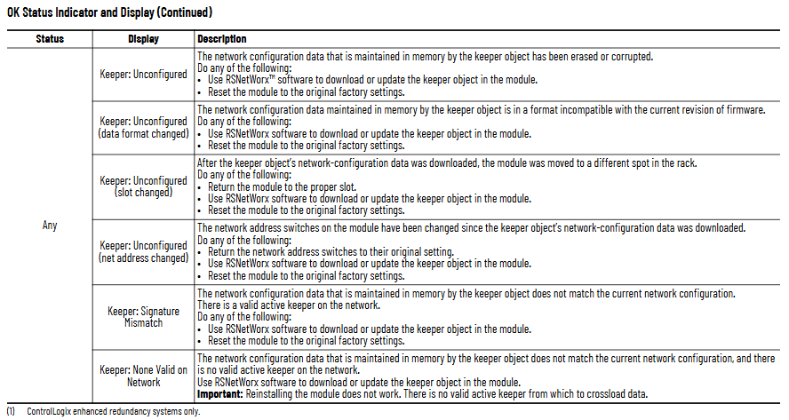
By using the OK status indicator light and network channel indicator light (A/B) of the module to locate the fault, the key status interpretation is as follows:
(1) OK status indicator light (core fault diagnosis)
Reason and solution for malfunction of indicator light status display information
Turn off power failure or internal failure: Check the power connection and module for tightness. If it is ineffective, replace the module
Reset Complete Change Switch Settings address to 00 (invalid): Reset valid address (01~99/98)
Frequent red FAIL power on test failure: replace module directly
Flashing red DUPLICATE NOTE DETECTED Network address conflict: Replace with unique address
Flashing red Image update Needed firmware needs to be updated: Use ControlFLASH software to upgrade Boot image
Evergreen/Blinking Green CPU=xx% (xx ≥ 80) CPU utilization is too high (over 80%): Check the number of network connections and optimize the control program
Blinking green NET ERR network wiring error or no other nodes: Check cables, terminators, and ensure that at least one other node is online
(2) Network channel indicator light (A/B channel status)
Interpretation of indicator light status channel (A/B) status
Evergreen is operating normally, and channel communication is functioning properly
Flashing green/extinguishing temporary error, module can self recover
Flashing red/off media malfunction (such as disconnection, looseness) or no other nodes: Check cables, terminators, and add online nodes
Constant red channel fault: power off reset module, if ineffective, contact Rockwell technical support
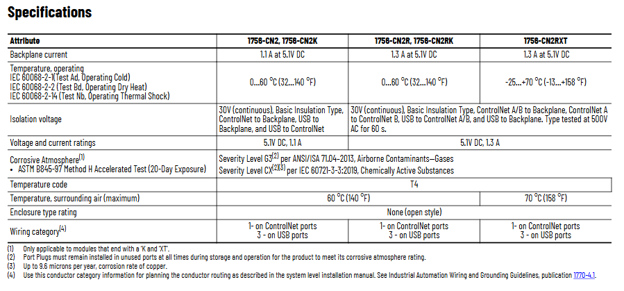
Key technical parameters
Parameter category 1756-CN2/CN2K 1756-CN2R/CN2RK 1756-CN2RXT
Backboard current 1.1A (5.1V DC) 1.3A (5.1V DC) 1.3A (5.1V DC)
Working temperature: 0~60 ℃ (32~140 ℉) 0~60 ℃ (32~140 ℉) -25~70 ℃ (-13~158 ℉)
Isolation voltage 30V DC (continuous), basic insulation between ControlNet/USB and backplane (500V AC withstand voltage for 60 seconds) on the same left (redundant models additionally support A/B channel isolation) on the same left
Anti corrosion grade (with "K") ASTM B845-97 G3 grade (ANSI/ISA 71.04), IEC 60721-3-3 CX grade same as left
The wiring category for ControlNet ports is Class 1, and for USB ports it is Class 3. Same as left

- ABB
- General Electric
- EMERSON
- Honeywell
- HIMA
- ALSTOM
- Rolls-Royce
- MOTOROLA
- Rockwell
- Siemens
- Woodward
- YOKOGAWA
- FOXBORO
- KOLLMORGEN
- MOOG
- KB
- YAMAHA
- BENDER
- TEKTRONIX
- Westinghouse
- AMAT
- AB
- XYCOM
- Yaskawa
- B&R
- Schneider
- Kongsberg
- NI
- WATLOW
- ProSoft
- SEW
- ADVANCED
- Reliance
- TRICONEX
- METSO
- MAN
- Advantest
- STUDER
- KONGSBERG
- DANAHER MOTION
- Bently
- Galil
- EATON
- MOLEX
- DEIF
- B&W
- ZYGO
- Aerotech
- DANFOSS
- Beijer
- Moxa
- Rexroth
- Johnson
- WAGO
- TOSHIBA
- BMCM
- SMC
- HITACHI
- HIRSCHMANN
- Application field
- XP POWER
- CTI
- TRICON
- STOBER
- Thinklogical
- Horner Automation
- Meggitt
- Fanuc
- Baldor
- SHINKAWA
- Other Brands


