How to install the Rockwell Automation 1757-SRM (B-series) module?
How to install the Rockwell Automation 1757-SRM (B-series) module?
Basic Information
The installation instructions for the redundant modules of the Rockwell Automation 1757-SRM series B-type ProcessLogix and ControlLogix systems are designed to guide users in installing the redundant module into the ProcessLogix or ControlLogix redundant chassis, covering the entire process of installation preparation, operation steps, fault handling, technical specifications, and more.
Important User Information and Security Standards
(1) Definition of Core Security Warning
The document specifies the meanings of different security signs to avoid operational risks, as follows:
Meaning of identification
Warning: Operating scenarios in hazardous environments that may cause explosions, resulting in personal injury, property damage, or economic loss
IMPORTANT annotation is crucial for the successful application and understanding of product information
Attention: Identify operational methods that may result in personal injury, property damage, or economic loss, and explain how to identify and avoid hazards and consequences
Labels on or inside SHOCK HAZARD equipment (such as drivers, motors) warning of hazardous voltage
Labels on or inside BURN HAZARD equipment (such as drives, motors) warning that the surface may reach dangerous temperatures
(2) Special environmental usage requirements
North American Hazardous Area Certification: Products marked as "CL I, DIV 2, GP A, B, C, D" are only applicable to Class I, Division 2, Groups A, B, C, D hazardous areas and non hazardous areas; When the system is used in combination, the overall temperature level must be determined by the temperature code with the lowest "T" number, and the equipment combination must be inspected by the local competent department.
European Hazardous Place Certification: Products marked with EEx comply with EU Directive 94/9/EC, are suitable for potentially explosive environments, must be installed in enclosures that meet at least IP54 protection level (Class I, Zone 2 environment), and can only be used in conjunction with ATEX certified backplates; At the same time, the device is not resistant to sunlight and other ultraviolet radiation, and transient interference should be prevented from exceeding the rated voltage by more than 40% in Class I Zone 2 environment.
General environmental requirements: Suitable for industrial environments with pollution level 2, overvoltage category II applications (compliant with IEC 60664-1), with no need for derating at altitudes up to 2000 meters (6561 feet); Belonging to Group A industrial equipment under the IEC/CISPR 11 standard, if appropriate protective measures are not taken, conducted and radiated interference may affect electromagnetic compatibility; The device is of an open design and needs to be installed in an enclosure that meets specific environmental requirements. The enclosure must have flame retardancy (non-metallic enclosures must reach 5VA, V2, V1, V0 or equivalent flame retardant levels), and the interior must be accessible with tools.

Module basic information and installation preparation
(1) Module core functions and appearance
Functional positioning: The 1757-SRM (B series) module is used for redundant control of ProcessLogix and ControlLogix systems, achieving communication and status synchronization between the primary and backup chassis through fiber optic connections, ensuring smooth switching in case of system failures.
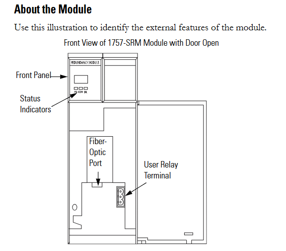
Appearance structure: The front includes status indicator lights, fiber optic ports, and user relay terminals. These components are required to achieve module status monitoring, fiber optic connections, and external device control (such as relay linkage).
(2) Preparation before installation
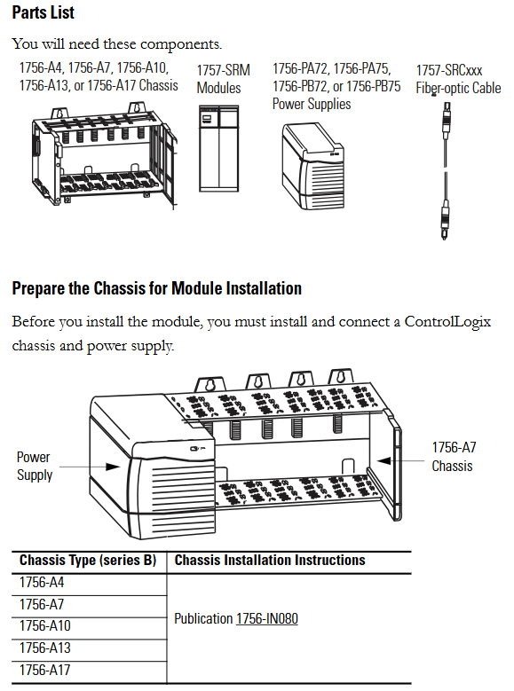
Component List: Prepare 1756-A4/A7/A10/A13/A17 series chassis, 1757-SRM module, 1756-PA72/PA75/PB72/PB75 series power supply, and 1757-SRCxxx series fiber optic cable.
Static electricity protection: The module is sensitive to static electricity. Before operation, it is necessary to touch a grounded object to release static electricity and wear a certified grounding wristband to avoid touching the connectors/pins and internal circuit components of the component board. When idle, it should be stored in anti-static packaging and an anti-static workstation should be used when conditions permit.
Chassis and power pre-processing: The ControlLogix chassis and power supply need to be installed and connected first. Different models of chassis (such as 1756-A4/A7, etc.) and power supplies (such as 1756-PA72/C, 1756-PB72/B, etc.) should refer to the corresponding installation instructions (such as 1756-IN080, 1756-IN078, etc.).
Module slot selection: The recommended slot positions for different models of chassis are different. For example, slot 1 or 2 is recommended for the 1756-A4 chassis, and slot 4 or 5 is recommended for the 1756-A7 chassis. It is necessary to strictly install according to the recommended positions to ensure normal communication and redundancy functions.

Redundant system assembly steps
(1) Core installation process
- ABB
- General Electric
- EMERSON
- Honeywell
- HIMA
- ALSTOM
- Rolls-Royce
- MOTOROLA
- Rockwell
- Siemens
- Woodward
- YOKOGAWA
- FOXBORO
- KOLLMORGEN
- MOOG
- KB
- YAMAHA
- BENDER
- TEKTRONIX
- Westinghouse
- AMAT
- AB
- XYCOM
- Yaskawa
- B&R
- Schneider
- Kongsberg
- NI
- WATLOW
- ProSoft
- SEW
- ADVANCED
- Reliance
- TRICONEX
- METSO
- MAN
- Advantest
- STUDER
- KONGSBERG
- DANAHER MOTION
- Bently
- Galil
- EATON
- MOLEX
- DEIF
- B&W
- ZYGO
- Aerotech
- DANFOSS
- Beijer
- Moxa
- Rexroth
- Johnson
- WAGO
- TOSHIBA
- BMCM
- SMC
- HITACHI
- HIRSCHMANN
- Application field
- XP POWER
- CTI
- TRICON
- STOBER
- Thinklogical
- Horner Automation
- Meggitt
- Fanuc
- Baldor
- SHINKAWA
- Other Brands


