
Rockwell Automation 1794 Series FLEX I/O Digital Input Module
Rockwell Automation 1794 Series FLEX I/O Digital Input Module
Product Overview and Installation Preparation
(1) Product Core Information
Functional positioning: The 1794 series module is a FLEX I/O digital input module used for collecting digital signals (such as sensor and switch status) in industrial automation systems. It is transmitted through Flexbus in conjunction with terminal bases and supports 2-wire/3-wire input devices. Different models correspond to different input channel numbers (8/16/32 channels).
Hardware composition: The module needs to be installed on the 1794 series terminal base (such as 1794-TB3, 1794-TB32, etc.), and the core components include Flexbus connectors (for communication with adjacent bases/adapters), locking mechanisms (fixed modules), key switches (for base configuration), and status indicator lights (yellow, corresponding to the signal status of each input channel).
(2) Preparation before installation
Compatibility confirmation: It is necessary to use a specified communication adapter to ensure normal functionality. For example, 1794-IB32/IB32K requires the use of Remote I/O 1794-ASB (E series and above), ControlNet 1794-ACN15 (C series, firmware 4.1 and above), etc; Programming requires the use of Studio 5000 Logix Designer V20 or higher versions.
Tools and materials: Prepare suitable screwdrivers (for fixing terminal base screws), anti-static tools (grounding wristbands, anti-static cloth), wires that meet specifications (referring to terminal base requirements, usually 22-14 AWG shielded copper wire), DIN rails (made of galvanized chromate passivated steel material to ensure good grounding and avoid poor conductors such as aluminum/plastic).
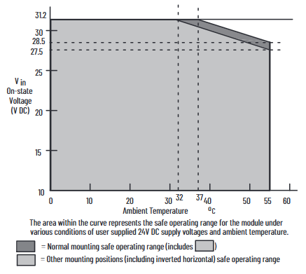
Environmental inspection: Confirm that the installation environment meets the requirements - pollution level 2 (industrial environment), overvoltage category II (EN/IEC 60664-1), altitude ≤ 2000 meters (no need to reduce capacity), and working temperature matching model (IB8/IB16 is -20~+55 ℃, IB32/IB32K is 0~+55 ℃).
Installation and wiring steps
(1) Module installation process
Base configuration: Rotate the key switch (position 3) on the terminal base to the "2" position (corresponding to the module type), ensuring that the Flexbus connector is fully pushed to the left and properly docked with the adjacent base/adapter.
Module alignment: Check if the pins at the bottom of the module are straight, align the alignment rod (position 6) of the module with the groove of the base (position 5), press the module evenly until the locking mechanism (position 2) clicks into the base, and confirm that the module is securely attached to the base.
Cleaning and inspection: During installation, avoid metal debris and wire residue from falling into the module to prevent short circuit damage after power on; After installation, check if all connections are secure and if the pins are not bent.
(2) Wiring method by model
1. 1794-IB8/IB16 (with 1794-TB3/TB3S base)
Wiring steps and operation details
Connect the signal line of the input device to the corresponding terminal of "A row (0-15)" (e.g. Input 0 is connected to A-0, Input 1 is connected to A-1)
Connect the+V DC power cord of the input device to the corresponding terminal of "C row (34-51)" (such as Input 0 connected to C-35), and all+V terminals in C row are internally connected; Connect the DC common terminal (3-wire device) to the corresponding terminal of "B row (16-33)" (such as Input 0 connected to B-17), and the B row common terminal is internally connected
Main power connection+V DC connection C-34, DC common terminal B-16
If the daisy chain extension needs to supply power to the next base, use jumper wires to connect the current base C-51 (+V) to the next base C-34, and B-33 (common terminal) to the next base B-16
2. 1794-IB32/IB32K (with 1794-TB32/TB32S base)
The module is divided into two sets of inputs (0-15, 16-31) and requires independent wiring:
Input 0-15: Connect the signal line to "A row (0-15)",+V1 to C row 35/37/39/41, COM1 to C row 36/38/40/42;
Input 16-31: Connect the signal line to "B row (17-32, skip 16/33)",+V2 to C row 43/45/47/49, COM2 to C row 44/46/48/50;
When expanding,+V1 jumps to the next base power terminal through C-41, and COM1 jumps to C-42; +V2 jumps through C-49, COM2 jumps through C-50.
(3) Wiring precautions
2-wire devices only need to connect the signal line and power line, while 3-wire devices require an additional connection to the common terminal;
The insulation layer of the wire needs to be stripped to a suitable length (to avoid short circuits caused by excessive exposure), and the torque of the terminal screws needs to meet the requirements of the base (usually 0.6-0.8 Nm);
Grounding needs to be achieved through DIN rails, which are fixed every 200 millimeters. End anchors need to be installed at both ends to ensure continuous grounding and low impedance.
Module configuration method
(1) Core configuration parameters
The module sets the input filtering time through the "configuration word (handwriting)", and the memory mapping and filtering control bits are different for different models. The core adjusts the signal stability through the "input filtering time (FT)" to avoid interference and false triggering.
- OMRON
- ABB
- General Electric
- EMERSON
- Honeywell
- HIMA
- ALSTOM
- Rolls-Royce
- MOTOROLA
- Rockwell
- Siemens
- Woodward
- YOKOGAWA
- FOXBORO
- KOLLMORGEN
- MOOG
- KB
- YAMAHA
- BENDER
- TEKTRONIX
- Westinghouse
- AMAT
- AB
- XYCOM
- Yaskawa
- B&R
- Schneider
- KONGSBERG
- NI
- WATLOW
- ProSoft
- SEW
- ADVANCED
- Reliance
- TRICONEX
- METSO
- MAN
- Advantest
- STUDER
- DANAHER MOTION
- Bently
- Galil
- EATON
- MOLEX
- DEIF
- B&W
- ZYGO
- Aerotech
- DANFOSS
- Beijer
- Moxa
- Rexroth
- Johnson
- WAGO
- TOSHIBA
- BMCM
- SMC
- HITACHI
- HIRSCHMANN
- Application field
- XP POWER
- CTI
- TRICON
- STOBER
- Thinklogical
- Horner Automation
- Meggitt
- Fanuc
- Baldor
- SHINKAWA
- Other Brands
- UniOP
- KUKA
- Iba
- Beckhoff
- ADLINK
-
 National Instruments USB-6363 DAQ Device
-
 National Instruments NI 9467 GPS Module
-
 National Instruments USB-6351 DAQ Device
-
 National Instruments NI 6581 Adapter Module
-
 National Instruments 781045-01 Output Module
-
 National Instruments PCI-6225 DAQ Card
-
 National Instruments TRC-8543 CAN Cable
-
 National Instruments PXIe-1073 Chassis
-
 National Instruments USB-6003 DAQ Device
-
 National Instruments NI 9476 Output Module
-
 National Instruments myRIO-1900 Embedded Controller
-
 National Instruments NI-9263 Analog Output Module
-
 National Instruments 158561A-01L Ordering Part Number
-
 National Instruments 785024-01 Ordering Part Number
-
 National Instruments PCI-6510 Industrial Digital I/O Card
-
 National Instruments USB-6259 Multifunction DAQ Device
-
National Instruments USB-8452 I2C SPI Interface Device
-
 National Instruments PXI-8432 Serial Interface Module
-
 National Instruments PXIe-5644R Vector Signal Transceiver
-
 National Instruments PXI-2569 Relay Module
-
 National Instruments 781174-01 Module
-
 National Instruments 782000-01 Module
-
 National Instruments PXI-5152 Digitizer
-
 National Instruments PXI-6284 DAQ Card
-
 National Instruments PCI-1428 Frame Grabber
-
 National Instruments PXI-1050 Chassis
-
National Instruments NI USB-8486 Fieldbus
-
 National Instruments NI 9862 CAN Module
-
 National Instruments NI 9146 FPGA Chassis
-
 National Instruments PXI-8108 Controller
-
 National Instruments NI SWB-2816A Matrix Module
-
 National Instruments NI 9269 Analog Output Module
-
National Instruments PCI-6031E Multifunction DAQ Card
-
National Instruments PXI-6713 Analog Output Module
-
 National Instruments NI 9216 RTD Input Module
-
 National Instruments NI-9237 Strain Bridge Input Module
-
National Instruments PXI-5124 High Resolution Digitizer
-
National Instruments USB-6343 X Series DAQ Device
-
 National Instruments PXIe-6536 Digital I/O Module
-
 National Instruments CAL-4330 Calibration Fixture
-
 National Instruments PXI-4110 Programmable Power Supply
-
 National Instruments 781503-01 Input Module
-
 National Instruments FP-AI-V10 Module
-
National Instruments PXI-5114 Digitizer Card
-
 National Instruments PXIe-8398 MXI Module
-
 National Instruments cRIO-9056 Controller
-
 National Instruments PCI-6509 DIO Device
-
 National Instruments cRIO-9053 Controller
-
National Instruments 781056-01 Output Module
-
 National Instruments 782606-01 Input Module
-
 National Instruments cRIO-9112 Chassis
-
National Instruments PXIe-1078 Chassis
-
 National Instruments PCIe-6536 DIO Board
-
 National Instruments NI-9425 Input Module
-
 National Instruments PCI-5122 Digitizer Card
-
National Instruments 779072-01 Relay Module
-
 National Instruments 783703-01 DAQ Module
-
 National Instruments PXI-6515 Digital Module
-
National Instruments 781099-01 DAQ Device
-
National Instruments PXI-8183 PXI Controller
-
 National Instruments sbRIO-9626 Single-Board RIO Controller
-
National Instruments PXIe-1435 Camera Link Frame Grabber
-
 National Instruments NI 9237 Strain Bridge Input Module
-
National Instruments PXIe-4353 Thermocouple Input Module
-
National Instruments PCIe-6320 X Series DAQ Card
-
 National Instruments NI 1454 Compact Vision System
-
 National Instruments PCIe-6321 X Series DAQ Card
-
 National Instruments PXIe-5172 PXI Oscilloscope Module
-
 National Instruments cDAQ-9134 CompactDAQ Controller
-
 National Instruments cRIO-9063 CompactRIO Controller
-
 National Instruments PXI-4070 DMM Card
-
 National Instruments cFP-BP-4 Backplane
-
National Instruments 779521-01 Bridge Module
-
 National Instruments cDAQ-9172 Chassis
-
 National Instruments NI 9236 Strain Module
-
National Instruments PXI-1042Q Chassis
-
 National Instruments SCXI-1102 Input Module
-
 National Instruments 776990-01 Input Module
-
 National Instruments PXI-1045 PXI Chassis
-
 National Instruments PCIe-6251 DAQ Device
-
 National Instruments NI 9219 Universal Analog Input Module
-
National Instruments NI 9215 BNC Analog Input Module
-
 National Instruments PXIe-6570 Digital Pattern Instrument
-
National Instruments NI-9477 Digital Output Module
-
National Instruments NI 9145 EtherCAT Chassis
-
 National Instruments PCI-6521 Industrial Digital I/O Card
-
 National Instruments NI 9239 BNC Voltage Input Module
-
 National Instruments NI 9265 Current Output Module
-
 National Instruments NI 9212 Thermocouple Input Module
-
 National Instruments PXI-6229 Multifunction DAQ Module
-
 National Instruments NI-9146 Chassis
-
 National Instruments PXIe-5622 Digitizer
-
 National Instruments PXI-6704 Output Module
-
National Instruments 782362-01 Input Module
-
National Instruments 779068-01 Digital Module
-
 National Instruments 781063-01 Output Module
-
 National Instruments PCI-7356 Motion Controller
-
 National Instruments 779787-01 Input Module
-
 National Instruments PXIe-1071 System
-
 National Instruments NI 9219 Input Module
-
 National Instruments NI 9214 Thermocouple Input Module
-
 National Instruments PXIe-1085 18-Slot Chassis
-
 National Instruments PCIe-6320 Multifunction DAQ Card
-
National Instruments USB-6211 Multifunction I/O Device
-
National Instruments USB-6341 X Series DAQ Device
-
National Instruments NI 9205 Analog Input Module
-
National Instruments NI 9149 8-Slot Chassis
-
 National Instruments PXIe-2569 Relay Module
-
National Instruments NI 9230 Sound and Vibration Module
-
National Instruments cRIO-9047 CompactRIO Controller
-
National Instruments PCI-6534 Digital IO Card
-
 National Instruments PXI-5122 Digitizer Module
-
 National Instruments cDAQ-9188XT Chassis
-
National Instruments cDAQ-9184 Ethernet Chassis
-
National Instruments USB-6225 OEM DAQ Device
-
National Instruments NI 9205 Input Module
-
National Instruments NI 9207 Input Module
-
National Instruments NI-9862 CAN Module
-
National Instruments 781156-01 CAN Module
-
 National Instruments FP-AO-200 Output Module
-
National Instruments NI 9264 Output Module
-
 National Instruments IC-3173 Controller
-
 National Instruments NI 9234 Vibration Module
-
 National Instruments SMB-2163 DIO Accessory
-
National Instruments PXIe-1062Q DSA System
-
 National Instruments USB-6289 DAQ Device
-
National Instruments NI 9233 Vibration Module
-
National Instruments PXIe-5840 VST


