
Rockwell Automation 1794 Series FLEX I/O Digital Input Module
Rockwell Automation 1794 Series FLEX I/O Digital Input Module
Product Overview and Installation Preparation
(1) Product Core Information
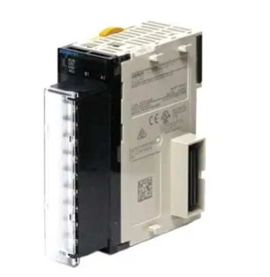
Functional positioning: The 1794 series module is a FLEX I/O digital input module used for collecting digital signals (such as sensor and switch status) in industrial automation systems. It is transmitted through Flexbus in conjunction with terminal bases and supports 2-wire/3-wire input devices. Different models correspond to different input channel numbers (8/16/32 channels).
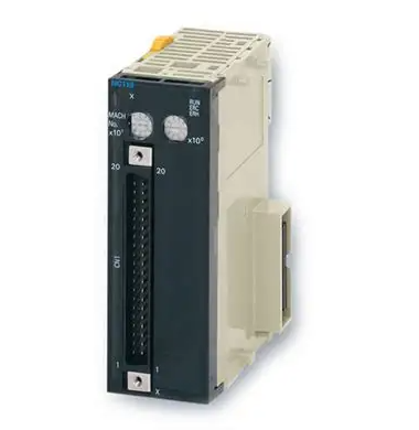
Hardware composition: The module needs to be installed on the 1794 series terminal base (such as 1794-TB3, 1794-TB32, etc.), and the core components include Flexbus connectors (for communication with adjacent bases/adapters), locking mechanisms (fixed modules), key switches (for base configuration), and status indicator lights (yellow, corresponding to the signal status of each input channel).
(2) Preparation before installation
Compatibility confirmation: It is necessary to use a specified communication adapter to ensure normal functionality. For example, 1794-IB32/IB32K requires the use of Remote I/O 1794-ASB (E series and above), ControlNet 1794-ACN15 (C series, firmware 4.1 and above), etc; Programming requires the use of Studio 5000 Logix Designer V20 or higher versions.
Tools and materials: Prepare suitable screwdrivers (for fixing terminal base screws), anti-static tools (grounding wristbands, anti-static cloth), wires that meet specifications (referring to terminal base requirements, usually 22-14 AWG shielded copper wire), DIN rails (made of galvanized chromate passivated steel material to ensure good grounding and avoid poor conductors such as aluminum/plastic).
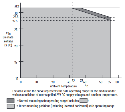
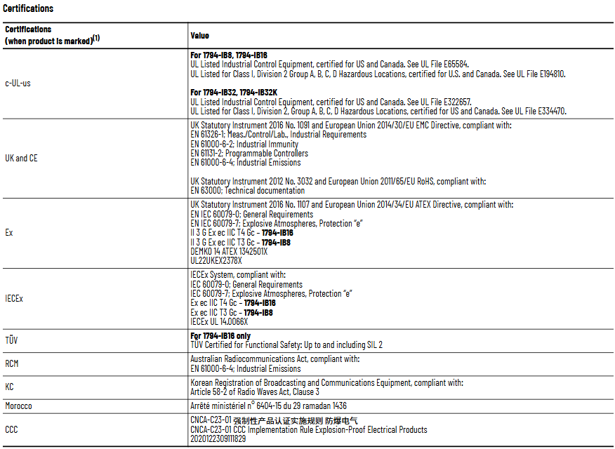
Environmental inspection: Confirm that the installation environment meets the requirements - pollution level 2 (industrial environment), overvoltage category II (EN/IEC 60664-1), altitude ≤ 2000 meters (no need to reduce capacity), and working temperature matching model (IB8/IB16 is -20~+55 ℃, IB32/IB32K is 0~+55 ℃).
Installation and wiring steps
(1) Module installation process
Base configuration: Rotate the key switch (position 3) on the terminal base to the "2" position (corresponding to the module type), ensuring that the Flexbus connector is fully pushed to the left and properly docked with the adjacent base/adapter.
Module alignment: Check if the pins at the bottom of the module are straight, align the alignment rod (position 6) of the module with the groove of the base (position 5), press the module evenly until the locking mechanism (position 2) clicks into the base, and confirm that the module is securely attached to the base.
Cleaning and inspection: During installation, avoid metal debris and wire residue from falling into the module to prevent short circuit damage after power on; After installation, check if all connections are secure and if the pins are not bent.
(2) Wiring method by model
1. 1794-IB8/IB16 (with 1794-TB3/TB3S base)
Wiring steps and operation details
Connect the signal line of the input device to the corresponding terminal of "A row (0-15)" (e.g. Input 0 is connected to A-0, Input 1 is connected to A-1)
Connect the+V DC power cord of the input device to the corresponding terminal of "C row (34-51)" (such as Input 0 connected to C-35), and all+V terminals in C row are internally connected; Connect the DC common terminal (3-wire device) to the corresponding terminal of "B row (16-33)" (such as Input 0 connected to B-17), and the B row common terminal is internally connected
Main power connection+V DC connection C-34, DC common terminal B-16
If the daisy chain extension needs to supply power to the next base, use jumper wires to connect the current base C-51 (+V) to the next base C-34, and B-33 (common terminal) to the next base B-16
2. 1794-IB32/IB32K (with 1794-TB32/TB32S base)
The module is divided into two sets of inputs (0-15, 16-31) and requires independent wiring:
Input 0-15: Connect the signal line to "A row (0-15)",+V1 to C row 35/37/39/41, COM1 to C row 36/38/40/42;
Input 16-31: Connect the signal line to "B row (17-32, skip 16/33)",+V2 to C row 43/45/47/49, COM2 to C row 44/46/48/50;
When expanding,+V1 jumps to the next base power terminal through C-41, and COM1 jumps to C-42; +V2 jumps through C-49, COM2 jumps through C-50.
(3) Wiring precautions
2-wire devices only need to connect the signal line and power line, while 3-wire devices require an additional connection to the common terminal;
The insulation layer of the wire needs to be stripped to a suitable length (to avoid short circuits caused by excessive exposure), and the torque of the terminal screws needs to meet the requirements of the base (usually 0.6-0.8 Nm);
Grounding needs to be achieved through DIN rails, which are fixed every 200 millimeters. End anchors need to be installed at both ends to ensure continuous grounding and low impedance.
Module configuration method
(1) Core configuration parameters
The module sets the input filtering time through the "configuration word (handwriting)", and the memory mapping and filtering control bits are different for different models. The core adjusts the signal stability through the "input filtering time (FT)" to avoid interference and false triggering.
- ABB
- General Electric
- EMERSON
- Honeywell
- HIMA
- ALSTOM
- Rolls-Royce
- MOTOROLA
- Rockwell
- Siemens
- Woodward
- YOKOGAWA
- FOXBORO
- KOLLMORGEN
- MOOG
- KB
- YAMAHA
- BENDER
- TEKTRONIX
- Westinghouse
- AMAT
- AB
- XYCOM
- Yaskawa
- B&R
- Schneider
- Kongsberg
- NI
- WATLOW
- ProSoft
- SEW
- ADVANCED
- Reliance
- TRICONEX
- METSO
- MAN
- Advantest
- STUDER
- KONGSBERG
- DANAHER MOTION
- Bently
- Galil
- EATON
- MOLEX
- DEIF
- B&W
- ZYGO
- Aerotech
- DANFOSS
- Beijer
- Moxa
- Rexroth
- Johnson
- WAGO
- TOSHIBA
- BMCM
- SMC
- HITACHI
- HIRSCHMANN
- Application field
- XP POWER
- CTI
- TRICON
- STOBER
- Thinklogical
- Horner Automation
- Meggitt
- Fanuc
- Baldor
- SHINKAWA
- Other Brands
- UniOP
- KUKA
- Iba
-
 Schneider TM262L10MESE8T Logic Controller
 -
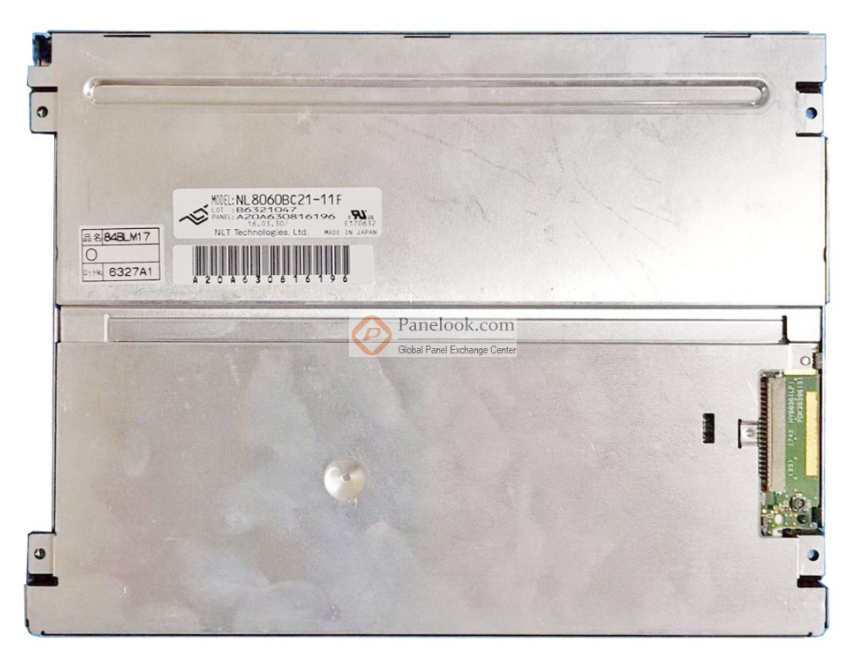 8.4-inch NL8060BC21-06 Industrial Display
 -
 B&R X20CP0411 Compact CPU Control Unit
 -
 Schneider TSX P572634 M Modicon Premium CPU
 -
 Omron NX1P2-1140DT-BA Machine Controller
 -
 Siemens Ams-M35-K202 C8451-A20-A53-7
 -
 Omron FH-2050 Automation Controller
 -
 Omron CJ1W-NCF71 Position Control Unit
 -
 PILZ 777750 Safety Relay
 -
 BES58-P0CA0P-CD0H3PB0 Encoder 85409
 -
 Siemens 3VL5763-1DC36-0AA0 Molded Case Breaker
 -
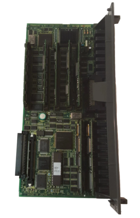 FANUC A16B-3200-0010 CPU Card
 -
 HINE DESIGN R94-1164 PLC Control Box 144760
 -
 Siemens PCU 50.5-C 6FC5210-0DF52-2AA0
 -
 PILZ PNOZ M0P Safety Relay 773110
 -
 Fanuc A20B-2101-0820 Control Circuit Board
 -
 Siemens 3SK1121-1AB40 Safety Relay
 -
 Pilz 772120 Safety Relay Expansion Module
 -
 Mitsubishi AX71 Input Module 16 Point
 -
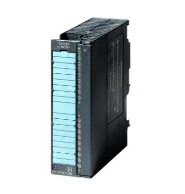 Siemens 6ES7350-1AH03-0AE0 S7-300 Extension
 -
 Fanuc A16B-3200-0010 CPU Card
 -
 Omron CJ1W-SCW22 Serial Communication Unit
 -
 Siemens 6SN1118-0DM21-0AA0 Control Module
 -
 Renishaw PHC10-3PLUS Controller Module
 -
 ABB AX521 1SAP250100R0001 Module
 -
 Omron NA5-9W001B-V1 PLC Module HMI
 -
 Infineon FF1000R17IE4 IGBT Power Module
 -
 Omron CJ1W-DA08C Analog Output Module
 -
 Omron CJ1G CPU45H CJ1H CPU66H CJ1G CPU43H CJ1W PA202
 -
 Omron CJ1W-DA041 Analog Output Module
 -
 Inductotherm 170-8031 PLC Control Module
 -
 Fuji Electric FPB56HR-A10 Programmable Logic Controller
 -
 Siemens 6SN1145-1BA01-0BA1 Infeed Regenerative Module
 -
 PILZ 777949 PSWZ X1P Safety Relay
 -
 Schneider 140NOM25200 DIO Head-end Adaptor
 -
 Siemens PXC5.E003 Controller BPZ
 -
 Schneider BMXEHC0800 Fast Counting Module 10kHz
 -
 Schneider BMXART0814 Isolated Thermocouple Inputs
 -
 Schneider BMXNOE0100 Ethernet Module 10 100 RJ45
 -
 LMX06-NS05 Sensor Industrial Proximity Switch
 -
 Siemens 6SN1145-1BB00-0FA1 Power Supply 156kW
 -
 Pro-face GP2500-LG41-24V HMI Graphic Panel
 -
Keyence CV-3001 Vision System CV3OO1
-
 Siemens 6GK5204-2BB10-2AA3 Ethernet Module
 -
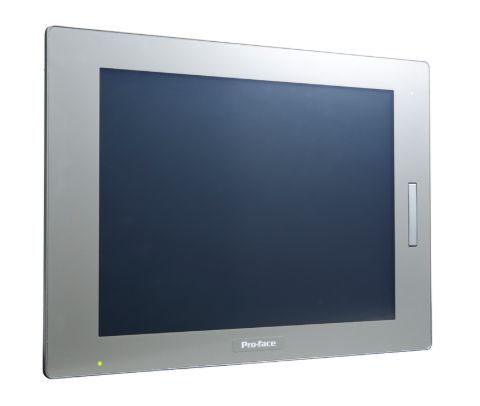 Pro-face PFXSP5500TPD 10.4in HMI LCD Display
 -
 Eu Automation 140DRA84000 Modicon Quantum Module
 -
 Siemens 6FC5210-0DF31-2AA0 Sinumerik PCU 50.3-C
 -
 Siemens 6SL3040-1NC00-0AA0 Sinumerik NX10.3 Extension
 -
 Gould AS-884A-111 Modicon 884 Controller
 -
 Allen Bradley 1336E-BRF30-AA-EN-HA2-L5 Impact Drive
 -
 Siemens 6FC5110-0BB02-0AA1 Sinumerik 840D CPU Card
 -
 Pilz 773500 PNOZmulti Expansion Module
 -
 Siemens 6ES7350-1AH03-0AE0 S7-300 Counter Module
 -
 Siemens 6FC5110-0DB01-0AA1 Sinumerik 840D Card
 -
 HPM 1D703-0040 Command 9000 VGA Console Board
 -
 OMRON CJ1W-PTS52 Temperature Unit
 -
 Sacs Technique PCD4.M12 Module
 -
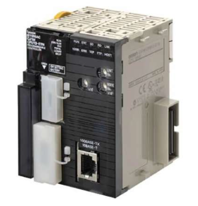 OMRON CJ1M-CPU11-ETN Ethernet CPU
 -
 OMRON CJ1M-CPU23 PLC CPU Unit
 -
 OMRON NX-SID800 Safety Input Unit
 -
 GE Fanuc Series 90-30 PLC
 -
 OMRON CJ1W-NCF71 Position Control
 -
 OMRON CJ1W-AD081-V1 Analog Input
 -
 OMRON FZ-S2M Vision Camera
 -
 OMRON R88D-UEP20V Servo Driver
 -
 OMRON F500-C10-ETN Vision Controller
 -
 OMRON CS1W-DA041 Analog Output Module
 -
 PRO-FACE GP577R-TC41-24VP HMI Panel
 -
 TRUTZSCHLER RAK 1 492-58.430.000 PLC Module
 -
 OMRON NX-OD5256 Output Module
 -
 Siemens 6AG1214-1AG40-4XB0 PLC
 -
 OMRON CJ1W-AD081-V1 Analog Unit
 -
 OMRON C500-CPU11-E PLC CPU
 -
 OMRON NX-ECC201 EtherCAT Coupler
 -
 OMRON F300-A20S Camera Interface
 -
 Mitsubishi 80173-109-01 PLC Module
 -
 Fanuc A16B-2200-0141 PCB Board
 -
 Lenze EPL10200 PLC Module
 -
 OMRON CJ1M-CPU13 PLC CPU Unit
 -
 Yaskawa SGMPH-04AAA61D-OY Motor
 -
 OMRON NX-SOD400 Safety Output
 -
 Control Techniques V1800 Flux Vector Drive
 -
 Yaskawa SGDH-04AE-OY Servo Drive
 -
 OMRON NT-DRT21 DeviceNet Interface
 -
 OMRON C500-RM001-V1 Remote I/O Master
 -
 OMRON C500-AD006 Analog Input Module
 -
 OMRON 3G3MV-A4055 Inverter Drive
 -
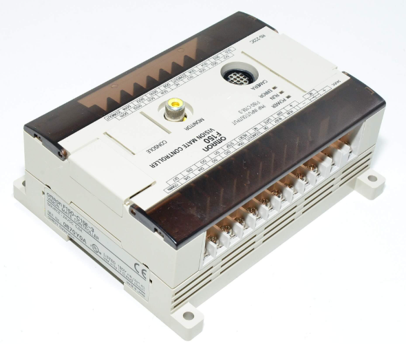 OMRON F150-C15E-3 Vision Mate Controller
 -
 OMRON CS1G-CPU44H PLC CPU
 -
 GE Fanuc DS6800CCIE1E1D CPU Module
 -
 Omron CP1L-M30DR-A PLC CP1W-CIF01 CPU Unit
 -
 Heraeus 585923 2M130 M8 Electrode Assembly Sensor
 -
 Omron C40P-EDT1-D C Series PLC Controller
 -
 Yaskawa SGMGH-09DCA6F-OY Servo Motor SGDH Driver
 -
 Datalogic SG-BWS-T4-MT Safety Control Unit Category 4
 -
 Pro-face PFXLM4301TADDC HMI Controller LT-4301M
 -
 Mitsubishi FX1N-60MR-DS PLC Main Unit 60 I/O
 -
 Omron NJ501-1320 Sysmac Database Connection CPU
 -
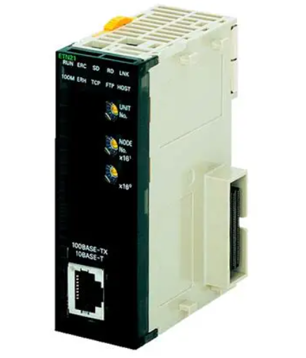
 Omron CJ1W-ETN21 Ethernet Unit CJ Series Module
 -
 Siemens 6ES7517-3AP00-0AB0 CPU 1517-3 PN/DP
 -
 Pasaban MTC-3052 Fast I/O PLC Module
 -
 Mitsubishi FX3U-128MR/ES-A PLC
 -
 OMRON CS1W-CLK21 Controller Link Unit
 -
 Yokogawa ADV151-E63 Digital Input Module
 -
 Allen Bradley MPL-B680B-M-X227 Motor
 -
 OMRON CJ1W-NC413 4-Axis Position Unit
 -
 Yaskawa SGMGH-30DCA6H-OY Servo Motor
 -
 Bosch 1070075337-101 Output Card
 -
 OMRON CQM1-CPU45-EV1 PLC CPU Unit
 -
 Siemens 6SE7090-0XX84-0AG1 CU3 Control Module
 -
 OMRON CQM1-TC101 Temperature Control Module
 -
 MOOG OEM-1030-422 Wind Energy PLC Controller
 -
 OMRON ZFX-C15 Vision Sensor
 -
 Square D 8702SCO2V02 Reversing Contactor
 -
 OMRON C20-LK201-EV1 PLC Link Adapter
 -
 OMRON NB7W-TW01B HMI PLC
 -
 Siemens 7ME6920-1AA10-1AA0 Flow Transmitter
 -
 Allen Bradley 1791-8BR Block I/O Module
 -
 OMRON CQM1-AD041 Analog Input Module
 -
 OMRON CJ1M-CPU21 PLC Module
 -
 Omron Z500-MC10E-001 Laser Profile Controller
 -
 Omron NA5-7W001B-V1 NA Series Programmable Terminal HMI
 -
 Allen-Bradley 1606-XLS960EE Power Supply 960W 24VDC
 -
 GE DS3800NEPB1F1E Power Excitation Board Mark IV
 -
 Yaskawa SGDH-04AE-OY Sigma-II Servo Drive 400W
 -
 Allen-Bradley 2711P-RBT7 PanelView Plus 7 Bezel
 -
 CCS PD3-3024-3-EI Digital Control Unit 3 Channel
 -
 Yaskawa CPU301 MP3300 Controller JAPMC-CP3301-2-E


