
Tektronix 3 Series Hybrid Domain Oscilloscope
Tektronix 3 Series Hybrid Domain Oscilloscope
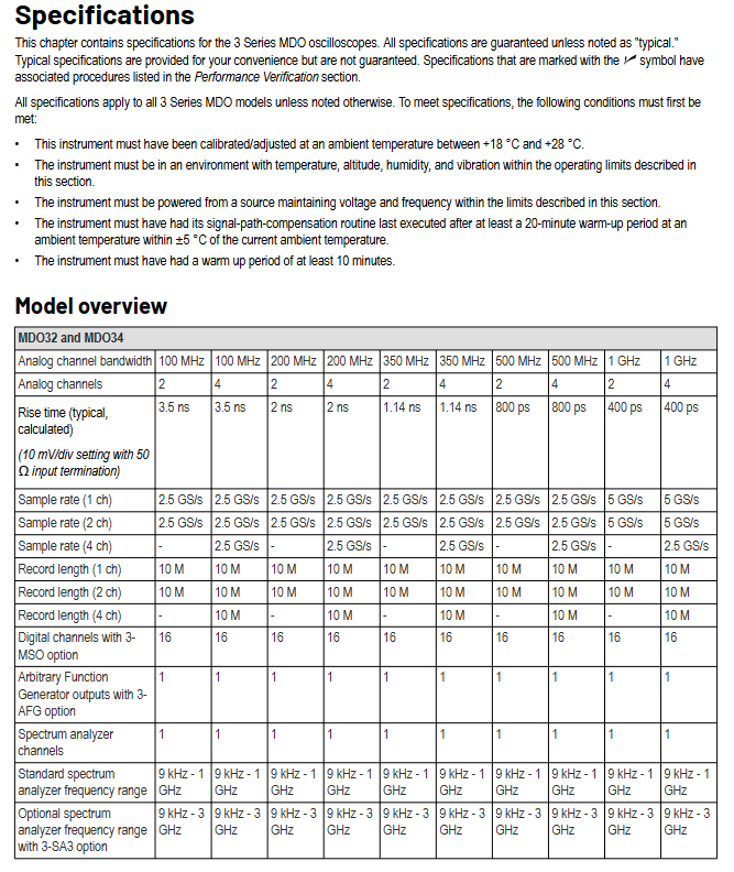
Core specification parameters (clarify instrument capability boundaries)
1. Model differences and overall architecture
The 3 series MDO oscilloscopes are divided into two categories: MDO32 (2-channel analog) and MDO34 (4-channel analog), with the same core architecture: "analog channel+digital channel (3-MSO option)+arbitrary function generator (3-AFG option)+spectrum analyzer" four in one, supporting synchronous observation of mixed domain signals (such as analog voltage+digital logic+RF signal).
Model Analog Channel Number Digital Channel Number (3-MSO) AFG Output (3-AFG) Spectrometer Channel Special Design
MDO32 2, 16, 1, 1 front panel with Aux In (external trigger)
MDO34 4 Road 16 Road 1 Road 1 Road No Aux In
2. Analog channel specifications (core measurement capability)
The analog channel is the foundation of an oscilloscope, and its parameters directly determine the voltage, bandwidth, and sampling accuracy. The document uses a large number of tables to clarify the differences between different bandwidth models (100MHz/200MHz/350MHz/500MHz/1GHz):
(1) Input and coupling characteristics
Input coupling: Supports AC and DC coupling, with a lower limit frequency of<10Hz (1M Ω) for AC coupling. When using a 10X probe, the lower limit is reduced by 10 times (<1Hz);
Input impedance: optional 1M Ω (± 1%, typical capacitance 13pF ± 2pF) or 50 Ω (± 1%), 1M Ω is suitable for high impedance signals (such as sensor output), and 50 Ω is suitable for RF/high-speed signals (matching transmission line impedance);
Maximum input voltage:
1M Ω DC coupling: 300VRMS (installation category II), derating at 20dB/decade for 4.5MHz-45MHz, derating at 14dB for 45MHz-450MHz, 5VRMS for>450MHz;
50 Ω: 5VRMS (peak value ≤± 20V, distortion factor DF ≤ 6.25%), although there is overvoltage protection, the pulse signal may damage the terminal resistance due to "detection delay".
(2) Bandwidth and sampling capability
Bandwidth: Bandwidth is strongly correlated with "vertical gear (V/div)", taking the 1GHz model as an example:
10mV/div-1V/div:DC-1.00GHz;
5mV/div-9.98mV/div:DC-500MHz;
2mV/div-4.98mV/div:DC-350MHz;
1mV/div-1.99mV/div:DC-150MHz。
Sampling rate:
1-2 channels enabled: up to 5GS/s (1GHz model), 2.5GS/s (≤ 500MHz model);
3-4 channels enabled: up to 2.5GS/s (all models);
The sampling rate varies with time/div, such as 2.5GS/s for 1ns/div and 100S/s for 1000s/div.
Record length: 1K-10M optional, with a maximum of 10M for 1 channel and 10M still supported for 4 channels, meeting the requirements for long-term signal acquisition (such as recording 2ms of signal at 10M point @ 5GS/s).
(3) Vertical accuracy index
DC gain accuracy:
1mV/div: ± 2.5%, with an additional 0.1% for every ℃ above 30 ℃;
2mV/div: ± 2.0%, with an additional 0.1% for every ℃ above 30 ℃;
5mV/div and above: ± 1.5%, with an additional 0.1% for every ℃ above 30 ℃.
DC balance: measures the signal offset at zero input, under 50 Ω DC coupling:
1mV/div:0.5div;
2mV/div:0.25div;
10mV/div and above: 0.2div;
When the temperature is above 40 ℃, an additional 0.01div is added for each ℃.
Noise level: Sampling mode, 50 Ω full bandwidth, 100mV/div gear:
1GHz model: 1.98mV (typical), 3.1mV (guaranteed);
100MHz model: 1.38mV (typical), 2.85mV (guaranteed).
3. Digital channel specifications (3-MSO option)
When configuring the 3-MSO option, the instrument supports 16 digital channels (D0-D15), suitable for synchronous observation of digital logic signals (such as FPGA, MCU pins):
Input characteristics: Input impedance 101k Ω (typical), input capacitance 8pF (typical), minimum signal 500mVpp, maximum signal+30V/-20V;
Timing accuracy: Skew (offset) between channels ≤ 500ps, minimum timing resolution of 2ns, minimum detectable pulse of 2.0ns (P6316 probe is required, and all 8 grounded channels are connected);
Threshold voltage: Range -15V -+25V, accuracy ± [130mV+3% x threshold setting] (SPC needs to be executed).
4. Arbitrary Function Generator (AFG, 3-AFG Options)
Built in 1 AFG, supporting 13 waveforms, can be used as a signal source to output excitation signals:
Waveform and Parameters:
Sine wave: frequency 0.1Hz-50MHz, amplitude 10mVpp-2.5Vpp (50 Ω), 20mVpp-5Vpp (1M Ω);
Square wave: frequency 0.1Hz-25MHz, duty cycle 10% -90%, minimum pulse width 10ns, rise/fall time 5ns (10% -90%);
Arbitrary wave: sampling rate of 250MS/s, recording length of 128k samples;
Accuracy index:
Frequency accuracy: ± 130ppm when ≤ 10kHz, ± 50ppm when>10kHz;
Amplitude accuracy: ± [1.5% x peak to peak value+1.5% x DC offset+1mV] (1kHz);
DC offset range: ± 1.25V (50 Ω), ± 2.5V (1M Ω), accuracy ± [1.5% x offset+1mV].
5. Specification of Spectrum Analyzer
Built in 1-channel spectrum analyzer, supporting RF signal analysis, standard frequency range 9kHz-1GHz, 3-SA3 option extended to 3GHz:
Frequency and bandwidth:
Resolution bandwidth (RBW): 20Hz-150MHz, adjusted in a 1-2-3-5 sequence, with Kaiser window ranging from 30Hz-150MHz;
Center frequency error: ± 10ppm (including aging, calibration, temperature stability, 1-year validity period);
Noise and distortion:
Display average noise level (DANL):<-136dBm/Hz at 5MHz-2GHz (guaranteed),<-140dBm/Hz (typical);
Harmonic distortion:<-55dBc (guaranteed),<-60dBc (typical) when 2nd harmonic>100MHz;
Input capability: Maximum continuous power+20dBm (0.1W), DC maximum ± 40V, pulse power+45dBm (32W,<10 μ s pulse width,<1% duty cycle).
6. Other key specifications (ensuring overall availability)
Display: 11.6-inch TFT capacitive touch screen, 1920 × 1080 resolution, 16.77 million colors, brightness of 450cd/m ² (new screen full brightness), supports touch operations (such as dragging cursor, switching menu);
I/O interface:
Ethernet: RJ-45, 10/100Mb/s, used for remote control and data transmission;
USB: 2 USB 2.0 hosts on the front panel (connected to USB flash drives and mice), 1 USB 2.0 host and 1 USB device on the back panel (supporting USBTMC);
HDMI: 19 pins, used for external display;
GPIB: Requires TEK-USB-488 adapter (optional), supports IEEE 488.2 protocol;
Environment and Machinery:
Working temperature -10 ℃ -+55 ℃, non working temperature -40 ℃ -+71 ℃;
Weight: MDO32 at 1GHz is about 5.26kg, MDO34 at 1GHz is about 5.31kg, with a soft shell (SC3) content of+1.81kg;
Dimensions: Height 252mm x Width 370mm x Depth 148.6mm.
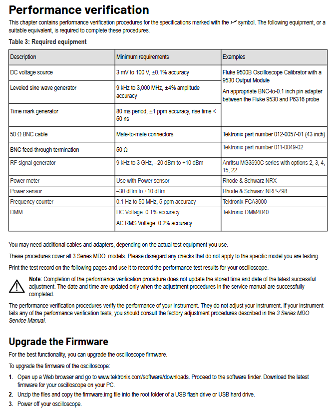
Performance verification process (verifying whether the instrument meets the standards)
Performance validation is the core chapter of the document, which includes over 20 tests covering both analog and digital channels AFG、 All core functions such as spectrum analyzer must be strictly executed according to the process to ensure reliable results.
1. Preparation before verification (basic conditions)
Instrument preheating and compensation: The instrument needs to be continuously powered on for 10 minutes to achieve thermal stability; Afterwards, execute "Signal Path Compensation (SPC)" - path: Utility → Calibration → Run SPC, taking 5-15 minutes per channel. If the ambient temperature changes by more than 5 ℃, SPC needs to be re executed.
Equipment connection and calibration:
The oscilloscope and all testing equipment (such as DC voltage sources and power meters) must be connected to the "same AC circuit" to avoid testing errors caused by ground offsets between different circuits; If unsure, it can be connected through a common ground power strip;
Before testing, it is necessary to calibrate the "signal source accuracy", such as verifying the DC voltage source output with a high-precision DMM (such as Tektronix DMM4040) and verifying the frequency of the sine wave generator with a frequency counter.
List of required equipment (Table 3): The document specifies the "minimum requirements" to avoid invalid test results due to insufficient equipment accuracy. The core equipment is as follows:
Equipment Name Minimum Requirements Example Model Usage
DC voltage source 3mV-100V, ± 0.1% accuracy Fluke 9500B (equipped with 9530 module) provides DC excitation, tests gain and offset accuracy
Level sine wave generator 9kHz-3000MHz, ± 4% amplitude accuracy Anritsu MG3690C provides AC excitation, tests bandwidth and noise
Time stamp generator with 80ms cycle, ± 1ppm accuracy, rise time<50ns - test sampling rate, delay accuracy
Power meter+sensor sensor range -30dBm -+10dBm Rohde&Schwarz NRX+NRP-Z98 testing spectrometer amplitude accuracy
Frequency counter 0.1Hz-50MHz, 5ppm accuracy Tektronix FCA3000 testing AFG, DVM frequency accuracy
Auxiliary accessories: 50 Ω BNC cable, 50 Ω straight through terminal Tektronix 012-0057-01 matching impedance to reduce signal reflection
2. Core testing projects and detailed processes
(1) Basic testing: Self check and SPC (to verify that the instrument hardware is functioning properly)
System diagnosis (self-test):
Disconnect all probes and cables, and reset the instrument by pressing the "Default Setup" button on the front panel;
Touch "Utility" → "Self Test" → "Run Self Test", wait for 5-10 minutes (including hardware, software, and interface testing);
After self inspection is completed, confirm that all items are "Passed"; If it fails, record the failure item (such as' RF channel not responding ') and contact Tektronix support.
Signal Path Compensation (SPC):
After passing the self-test, press "Default Setup", touch "Utility" → "Calibration" → "Run SPC";
During the compensation process, the instrument cannot be operated. After completion, confirm "SPC Status=Passed";
SPC is a prerequisite for all subsequent accuracy tests, and failure to pass cannot guarantee the validity of the test results.
(2) Simulation channel key testing (core function verification)
① Input terminal testing (verifying impedance accuracy)
Test purpose: To confirm whether the 1M Ω/50 Ω input impedance is within the qualified range, and to avoid signal attenuation/reflection caused by impedance mismatch.
Testing process:
Connect a DC voltage source (such as Fluke 9500B) to channel 1, with the voltage source set to "1M Ω output impedance";
Press "Default Setup" for the instrument, set channel 1 to a vertical gear of 10mV/div and a termination impedance of 1M Ω;
Measure the input impedance of channel 1 using a voltage source, and record the value within the range of 990k Ω to 1.01M Ω;
Switch the vertical gear to 100mV/div, repeat the measurement, and the impedance still needs to be between 990k Ω and 1.01M Ω;
Switch the termination impedance of the instrument to 50 Ω, set the output impedance of the voltage source to 50 Ω, repeat the test, and the impedance should be between 49.5 Ω and 50.5 Ω;
Repeat the above steps for all channels (MDO32 tests 1-2 channels, MDO34 tests 1-4 channels).
② DC balance test (verifying zero input offset)
Test objective: To measure the "offset of the signal at zero input", as excessive offset can lead to measurement errors in DC small signals.
Testing process:
Connect channel 1 to a 50 Ω BNC direct terminal (no signal input), press "Default Setup";
Channel 1 setting: Vertical gear 1mV/div, termination impedance 50 Ω, bandwidth limit 20MHz, acquisition mode "Average (16 waveform)";
Touch "Measure" → "Amplitude" → "Mean", add mean measurement, and record mean voltage;
Convert the average voltage to "div" (div=voltage/vertical gear), which should be within the range of -0.5div -+0.5div;
Switch the vertical gear to 2mV/div (allowed -0.25div -+0.25div), 10mV/div (allowed -0.2div -+0.25div), and repeat the measurement;
Switch bandwidth limit to 250MHz, Full, terminate impedance to 1M Ω, repeat test;
Repeat the above steps for all channels.
③ Simulated bandwidth test (verifying frequency response)
Test objective: To confirm whether the "-3dB bandwidth" of the instrument meets the standard at different vertical gears, as insufficient bandwidth can cause high-speed signal distortion.
Testing process (using 1GHz model as an example):
Connect the level sine wave generator to channel 1, with an output impedance of 50 Ω and a termination impedance of 50 Ω for instrument channel 1;
Instrument settings: vertical gear 10mV/div, acquisition mode "Sample", horizontal gear 4ns/div;
The generator outputs a 10MHz, 8divpp signal (i.e. 80mVpp), and records the "Vin pp" (peak to peak measurement value);
Adjust the generator frequency to "1GHz" (the maximum bandwidth frequency corresponding to 10mV/div) and record "Vbw pp";
Calculate the gain as Vbw-pp/Vin pp, which should be ≥ 0.707 (-3dB point);
Switch the vertical gear to 5mV/div (maximum bandwidth frequency 500MHz), 2mV/div (350MHz), 1mV/div (150MHz), and repeat the test;
Repeat the above steps for all channels.
④ DC gain accuracy test (to verify the accuracy of DC signal amplification)
Test purpose: To confirm whether the instrument's "amplification ratio" for DC signals is accurate, as excessive gain error can lead to inaccurate voltage measurement.
Testing process:
Connect the DC voltage source to channel 1, with an output impedance of 1M Ω for the voltage source, a termination impedance of 1M Ω for instrument channel 1, and a bandwidth limit of 20MHz;
Instrument settings: Vertical gear 1mV/div, acquisition mode "Average (16 waveform)", trigger source "AC Line";
Voltage source output -3.5mV (Vnegative), record the mean measurement value "Vnegative measured";
Voltage source output+3.5mV (Vpositive), record the mean measurement value "Vpositive measured";
Calculate Vdiff=| Vnegative measured - Vpositive measured |, expected Vdiff=7mV (1mV/div x 7div);
Calculate gain accuracy=(Vdiff-7mV)/7mV) × 100%, within the range of -2.5% -+2.5%;
Switch the vertical gear to 2mV/div (allowed -2.0% -+2.0%), 5mV/div (allowed -1.5% -+1.5%), and repeat the test;
Repeat the above steps for all channels.
(3) AFG testing (verifying signal source accuracy)
① AFG frequency accuracy test
Testing process:
Connect the AFG output to the frequency counter, press "Default Setup" on the instrument, and touch "AFG";
AFG setting: waveform "sine wave", amplitude 2.5Vpp, load impedance 50 Ω, frequency 10kHz;
Read the frequency counter value within the range of 9.9987kHz-10.0013kHz (± 130ppm);
Switch the frequency to 50MHz (>10kHz, allowing ± 50ppm, i.e. 49.9975MHz-5.0025MHz) and repeat the test;
Switch the waveform to "square wave" with frequencies of 25kHz (± 130ppm allowed) and 25MHz (± 50ppm allowed), and repeat the test.
② AFG amplitude accuracy test
Testing process:
Connect AFG output to DMM, with a 50 Ω terminal in the middle string, and set "AC RMS measurement" in DMM;
AFG setting: waveform "square wave", frequency 1kHz, load impedance 50 Ω, amplitude 20mVpp;
To read the DMM value, it needs to be within the range of 9.35mV-10.65mV (± 1.5%+1mV);
Switch the amplitude to 1Vpp (allowing 490.5mV-509.5mV) and repeat the test.
(4) Spectrum analyzer testing (to verify RF analysis capability)
① Display Average Noise Level (DANL) Test
Test purpose: To measure the "inherent noise level" of the spectrometer, the lower the DANL, the better it can detect weak RF signals.
Testing process:
Connect the RF input to a 50 Ω terminal (no signal), press "Default Setup" on the instrument, and touch "RF";
RF settings: Trace "Average", detection mode "Average", reference level -15dBm, RBW Auto;
Set frequency range: 9kHz-50kHz, touch "Cursors" → "Marker", move the marker to "highest noise point", record DANL, need to be<-109dBm/Hz;
Switch the frequency range to 50kHz-5MHz (<-126dBm/Hz) and 5MHz-2GHz (<-136dBm/Hz), and repeat the test.
② Residual Stray Response Test
Test purpose: To confirm whether the "spurious signal without input" of the spectrum analyzer is within the qualified range, and excessive spurious will interfere with RF signal detection.
Testing process:
RF input connected to 50 Ω terminal, set reference level -15dBm, RBW 100kHz;
The frequency range is 9kHz-50kHz, and for observing stray signals, it is required to be<-78dBm;
Switch the frequency range to 50kHz-5MHz (<-78dBm), 5MHz-2GHz (<-78dBm,<-76dBm required at 1.25GHz), 2GHz-3GHz (<-78dBm,<-62dBm required at 2.5GHz), and record all excessive stray signals.
3. Test records and result processing
Test Record: The document provides a "Test Record" form (110 pages in total), which needs to be printed and filled in with the "lower limit value, test result, and upper limit value" for each test. For input terminal testing, the impedance value of "channel 1 1M Ω 10mV/div" needs to be recorded, and for DC balance testing, the "div" value needs to be recorded as evidence of instrument performance.
Result judgment and processing:
If the test result is within the range of "lower limit upper limit", it is judged as "Passed";
If it fails, first review the "operation steps, equipment settings" (such as whether SPC is executed and impedance is matched) to eliminate human errors;
If the operation is confirmed to be correct but still fails, the performance verification process "does not provide adjustment function", and it is necessary to refer to the "3 Series MDO Service Manual" to perform "factory calibration" (such as adjusting the analog channel gain resistance and AFG frequency reference); If calibration still fails, contact Tektronix for repair (North America 1-800-833-9200).
Test records and subsequent processing
Test record: The document provides a detailed table to record the "lower limit value test result upper limit value" for each test, which needs to be printed and filled in;
Result processing: Performance verification only judges whether it meets the standard, without adjusting the instrument; If the test fails, refer to the "3 Series MDO Service Manual" to perform factory calibration;
Calibration cycle: The validity period of the reference frequency error (± 10ppm) is 1 year, and it is recommended to calibrate once a year.
- OMRON
- ABB
- General Electric
- EMERSON
- Honeywell
- HIMA
- ALSTOM
- Rolls-Royce
- MOTOROLA
- Rockwell
- Siemens
- Woodward
- YOKOGAWA
- FOXBORO
- KOLLMORGEN
- MOOG
- KB
- YAMAHA
- BENDER
- TEKTRONIX
- Westinghouse
- AMAT
- AB
- XYCOM
- Yaskawa
- B&R
- Schneider
- KONGSBERG
- NI
- WATLOW
- ProSoft
- SEW
- ADVANCED
- Reliance
- TRICONEX
- METSO
- MAN
- Advantest
- STUDER
- DANAHER MOTION
- Bently
- Galil
- EATON
- MOLEX
- DEIF
- B&W
- ZYGO
- Aerotech
- DANFOSS
- Beijer
- Moxa
- Rexroth
- Johnson
- WAGO
- TOSHIBA
- BMCM
- SMC
- HITACHI
- HIRSCHMANN
- Application field
- XP POWER
- CTI
- TRICON
- STOBER
- Thinklogical
- Horner Automation
- Meggitt
- Fanuc
- Baldor
- SHINKAWA
- Other Brands
- UniOP
- KUKA
- Iba
- Beckhoff
-
 OMRON CJ1W-MD261 Mixed I/O Module
 -
 Omron NJ301-1100 PLC CPU eCat EIP Specs
 -
 Omron F500-C15-ETN Vision System PLC Module
 -
 Modicon M241-24IO TM/T2UK PLC with Ethernet
 -
 SIXNET YS-800-001 RTU PLC Module
 -
 BEMAC UST-202-D Interface Board 1307D V08B2
 -
 Yaskawa JANCD-MMOIC-02 Drive Circuit Board
 -
 ABB 3BSE005028R1 SDCS-COM-1 Comm Board
 -
 Omron 3G3MX2-A4110 A4150 Inverter Drives Specs
 -
 KEYENCE CA-E100 PLC Module
 -
 GE IC693ALG223-GB Analog Input Module Specs
 -
 ABB BAILEY IMMFP01 Multi Function Processor System
 -
 SIEMENS 6FC5372 0AA00 0AA1 NCU 7202 Controller
 -
Modicon TM241CE4 40I O Transistor Programmable Controller
-
 SIEMENS 6ES7 315 2EH13 0AB0 CPU 3152 PN DP
 -
 NORIS A1 91 PCB Card Rack Module System
 -
 SIEMENS 6ES7 313 5BE01 0AB0 Compact CPU
 -
 SCHNEIDER ELECTRIC S144B MICROLOGIC 60A Trip Unit
 -
 CNI PLC269 v3 Control Module Board Rev H
 -
ABB BAILEY IIMCP02 Processor Module
-
 OMRON NT20S ST121 EV3 Operator Interface Terminal
 -
 OMRON NS-CA001 Video Input Unit
 -
 GE Fanuc IC695CHS012 RX3i Backplane
 -
 Allen Bradley 2711E-K14C6 PanelView 1400e Terminal
 -
 Siemens Sinamics CCB 10000432.71 Power Cell
 -
 Siemens 6SL3210-1SE21-8UA0 Power Module PM340
 -
 Yaskawa CIMR-F7A20P4 AC Drive
 -
 Beckhoff EP1918-0002 EtherCAT Box I/O Module
 -
 OMRON CQM1-TC001 Temperature Control Module
 -
 GE Fanuc SGHA36AT0400 Industrial Contactor
 -
 OMRON NJ501-1500 PLC Machine Automation Controller
 -
 Mitsubishi MAZAK QX084 Power Supply MELDAS 500 CNC
 -
 B&R 0AC808.9 PLC Automation Module
 -
 OMRON CP1H-XA40DT1-D PLC Module
 -
 G&W Electric PLC15 5111 011 15kV Capnut Assembly
 -
 GE DS200SLCCG3AGH PCB Circuit Board
 -
 Siemens SINUMERIK 6FC3981-4FD PLC Extension
 -
 OMRON F300-DC I/O Image Processing Unit
 -
 FANUC A06B-0314-B002 AC Servo Motor
 -
 GC-S84 Programmable Controller Logic Module
 -
 PASABAN MONTELEC MTC3001-DC Drive Control PLC
 -
 Allen Bradley 100E460EJ11 Auxiliary Contactor
 -
 Bosch Rexroth 1070075337-101 Card Parameters
 -
 HMS Anybus AB7646-F Gateway Specifications
 -
 Bosch 062633-303401 CNC Servo PLC Card
 -
 TI 500-5023 Series PLC Power Supply
 -
 Siemens C98043-A7002-L1-12 Circuit Board
 -
 Omron E5CC-RX3A5M-000 Controller
 -
 CN-8032-L Profinet Network Adapter Module
 -
 Siemens 3TK2804-0BB4 Safety Relay Details
 -
 Toledo TTLM-2-1M I/O Load Module
 -
 NORIS A1-91 PLC Rack Board Specifications
 -
 Mitsubishi A3ACPUR21 MELSEC PLC CPU Module
 -
 Beckhoff EP7041‑3002 EtherCAT Box Digital Input Module
 -
 REER EOS2E 1053 EOS2R 1053 Safety Light Curtain
 -
 Mitsubishi Q80BD-J71BR11 MELSECNET/H Interface Board
 -
 Omron 3G3IV-B4220-EV2 VFD 400V 22kW
 -
 Allen-Bradley 96844671 1785-LT3 PLC-5/12 Processor Module
 -
 Pasaban MTC3001-DC Drive Control PLC Module
 -
 Omron CJ1M-CPU11 V4.0 PLC CPU Module
 -
 ABB CM579-PNIO B3 Communication Module
 -
 B&R X20 AI 4221 Analog Module
 -
 Siemens 6SY7000-0AC80 PLC Module
 -
 GE 531X300CCHAFM5 Control Card
 -
 AB 810-A15C Inverse Time Relay
 -
 WITTENSTEIN LP120X-MF2-20 Planetary Gear
 -
 Mitsubishi Kakoki E-01B-4130 PLC I/O Modules
 -
 ABB DSQC643 Safety Control Board
 -
 Siemens G26004-A2105-P100-2 PCB
 -
 OMRON F350-C10E Image Processing Unit
 -
 FUJI UG430H-TS1 HMI Touch Panel
 -
 Westronics CB100188-01 Rev F Board
 -
 Siemens 7MH4900-3AA01 Weighing Module
 -
 Gilbert & Nash Tracker 2000 Control Cabinet
 -
 OMRON CJ1M-CPU22 CPU Unit
 -
 OMRON F3SJ-E0625P25 Light Curtain
 -
 Siemens 3VA2340-5HL32-0AA0 Breaker
 -
 Mitsubishi Melsec A61P A2NCPU PLC System
 -
 Aeco 158-02 DSP-02 PCB Card
 -
 FUJI NP1PS-32R CPU Module
 -
 Siemens 6SL3040-1MA01-0AA0 Control Unit CU320-2 PN
 -
 Fuji RYE.75D PLC Driver AC Drive
 -
 Electro Cam PS-6144-24-P16M09-L-MB Programmable Limit Switch
 -
 Siemens C98043-A7001-L2-4 CUD1 Control Board
 -
 Pilz 312070 PSSu H PLC1 FS SN SD Safety Module
 -
 Siemens Plc42q4200atsn Circuit Breaker Fuse Box
 -
 GE Fanuc IC695ALG708-AB Analog Output Module Rx3i
 -
 Siemens 6SE7036-5GK84-1JC2 IGD8 Gate Driver Board
 -
 Charmilles 813078 852029 PLC PCB Robocut 2 CNC EDM
 -
 Siemens 6SL3130-1TE24-0AA0 Smart Line Module
 -
 Pasaban MTC3001-DC Drive Control PLC Module
 -
 Modicon AS-P890-000 Remote I/O Processor Power Supply
 -
 Siemens PXC100-PE96.A PXC Modular Controller
 -
 TOYO KEIKI P:CARD5 AVH-R YH-212 Industrial Control Card
 -
 Omron NS5-SQ00B-V2 HMI Touch Screen 5.7 Inch
 -
 Sciemetric SigPOD 1202-0H00 Data Acquisition Module
 -
 GE Fanuc IC693CPU331W CPU Module Series 90-30
 -
 Square D 8903SVO11V02 Lighting Contactor 200A
 -
 Beckhoff C9900-P224 Power Supply Unit 24V 10A
 -
 HSD PE323 PLC I/O Module
 -
 Pillar AB6406-11A Power Control Board
 -
 GE Fanuc IC693CPU331W CPU Module
 -
 FANUC A61L-0001-0072 LCD Monitor
 -
 AB 20D-D-011-A-0-EYNANANE Drive
 -
 AB 1785-L20B PLC-5/20 Processor
 -
 Siemens SIREC P/PA Recorder 7ND3021
 -
 Siemens D2E160-AH01-17 Fan Blower
 -
 Eaton 101073735-001 LEG Module
 -
 AB 1404-M605B-ENT Powermonitor 3000
 -
 OMRON CJ1W-MAD42 Analog I/O
 -
 Omron CJ1M-CPU13 V3.0 PLC CPU Module
 -
 Pe323 HSD PLC Module Industrial Controller
 -
 Pasaban MTC3001-DC Drive Control PLC Module
 -
 Mitsubishi R02CPU PLC Module MELSEC iQ-R
 -
 B&R X20DC2395 Digital Output Module 32 Ch
 -
 Hoffman A30N24ALP Enclosure with PLC Addons
 -
 Rieter PLC with RMC 24/5V 10 RMC188-1 RMC RIO-1
 -
 Allen-Bradley 1790D-TN4V0 CompactBlock LDX Base Block 4 AI
 -
 National Instruments NI 9242 Analog Input Module 4-Channel
 -
 ABB AO820 3BSE008546R1 Analog Output Module
 -
 Moeller XVC-101-C192K-K82 PLC
 -
 AB 440F-C4000P MatGuard Controller
 -
 AB 1692-ZRCLSS Protection Module
 -
 Schneider S48896 PLC Module
 -
 FANUC A02B-0303-C205 I/O Module
 -
 AB 1785-LT4 PLC-5/10 Processor
 -
 AB 1746-NO8V SLC 500 Analog Output
 -
 OMRON CQM1-TC001 Temperature Unit


