
Bently Nevada 3500/50M tachometer module
Bently Nevada 3500/50M tachometer module
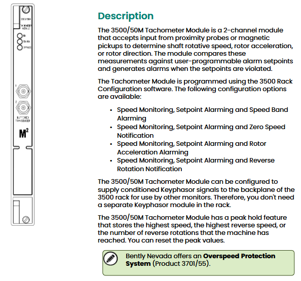
The Approximately Nevada 3500/50M tachometer module is a dual channel module designed specifically for mechanical equipment condition monitoring. It can receive signals from proximity probes or magneto electric sensors, enabling real-time monitoring of shaft speed, rotor acceleration, and rotation direction. It triggers alarms through programmable alarm thresholds and is widely used in rotating machinery such as industrial turbines, generators, and compressors. It also supports providing conditioned Keyphasor signals to the 3500 rack backplane without the need for additional Keyphasor modules.
Core functions and positioning
1. Core monitoring capability
The module supports four types of monitoring configuration schemes, which can be flexibly selected according to the scenario, covering key parameters such as speed, acceleration, and direction:
Configuration plan, monitoring parameters, applicable scenarios
Option 1: Speed monitoring, threshold alarm, and speed bandwidth alarm for devices that need to monitor the range of speed fluctuations (such as generators)
Scenario 2: Speed monitoring, threshold alarm, and zero speed notification require determining the start/stop status of the equipment (such as compressor start/stop confirmation)
Plan 3: Equipment for speed monitoring, threshold alarm, and rotor acceleration alarm to prevent sudden increase/decrease in speed (such as turbine overspeed acceleration prevention)
Option 4: Speed monitoring, threshold alarm, and reverse rotation notification for devices that prohibit reverse rotation (such as pump type mechanical anti reverse protection)
2. Featured Features
Keyphasor signal sharing: It can be configured to output conditioned Keyphasor signals to the 3500 rack backplane for use by other monitoring modules (such as vibration monitoring modules), reducing the number of modules in the rack.
Peak holding: Automatically stores the highest forward speed, highest reverse speed, and number of reversals during device operation. The peak can be manually reset for easy fault tracing.
Flexible alarm configuration: Supports two-level alarms (Alarm 1/Alarm 2), and the alarm threshold and delay time can be set by software to avoid false alarms (such as short-term speed fluctuations not triggering alarms).
Technical parameters
1. Input parameters
The module is compatible with two types of sensors, and attention should be paid to the usage restrictions of magneto electric sensors (see "Safety Warning"):
Parameters, specifications, and notes
The input signal source is close to the probe (recommended), and the magneto electric sensor does not support reverse monitoring or zero speed monitoring (the signal edge is unclear at low speeds, making it easy to misjudge)
The input signal range is+10.0V~-24.0V. If the signal exceeds the range, it is limited internally by the module to avoid damage
Input impedance standard: 20k Ω; TMR (Triple Modular Redundancy): 40k Ω; Built in isolation barrier: 7.15k Ω, suitable for different system requirements with different configurations
Minimum input frequency close to the probe: 0.0167Hz (1rpm, 1 pulse/rev); Magnetic electric sensor: 3.3Hz magnetic electric sensor does not support low-speed monitoring
The maximum input frequency of 20kHz corresponds to a maximum speed of 99999rpm (matching the number of pulses per revolution)
Number of pulses per revolution, rotor acceleration/zero speed channel: 1-255 pulses per revolution; Other channels: 0.0039~255 pulses per revolution, suitable for speed measuring gears with different numbers of teeth
2. Output parameters
Covering status indication, signal buffering, recording output, etc., to meet monitoring and data recording requirements:
Output type, specification, and function
Front panel LED OK (normal operation), TX/RX (rack communication), Bypass (bypass mode) intuitively judge the working status of the module
Buffer sensor output with 1 coaxial connector per channel (short circuit, ESD protection) for sensor signal multiplexing (such as simultaneous access to oscilloscope debugging)
The sensor power supply is 24VDC, with a maximum of 40mA per channel to provide power for the proximity probe
The recorder outputs a current signal proportional to the full range, with a resolution of 0.3662 µ A/bit, used for data recording and trend chart drawing. Short circuits do not affect module operation
Current output voltage range 0~+12VDC, load resistance 0~600 Ω, suitable for most industrial recorders
Output update rate of approximately 100ms to ensure real-time performance while avoiding data redundancy
3. Accuracy and alarm parameters
Parameters and specifications
Speed accuracy<100rpm: ± 0.1rpm; 100~10,000rpm:±1rpm; 10000~999999rpm: ± 0.01% true speed
Acceleration accuracy ± 20rpm/min
Alarm threshold range 0~100% full scale (software adjustable)
Alarm delay Alarm 1:1~60 seconds (1-second step); Alarm 2:1~60 seconds (0.1 second step size)
Alarm hysteresis 0.2~2.5V (user selectable to prevent frequent switching of alarms)
4. Physical and power consumption parameters
Module type, size (height x width x depth), weight, rack occupancy
- OMRON
- ABB
- General Electric
- EMERSON
- Honeywell
- HIMA
- ALSTOM
- Rolls-Royce
- MOTOROLA
- Rockwell
- Siemens
- Woodward
- YOKOGAWA
- FOXBORO
- KOLLMORGEN
- MOOG
- KB
- YAMAHA
- BENDER
- TEKTRONIX
- Westinghouse
- AMAT
- AB
- XYCOM
- Yaskawa
- B&R
- Schneider
- KONGSBERG
- NI
- WATLOW
- ProSoft
- SEW
- ADVANCED
- Reliance
- TRICONEX
- METSO
- MAN
- Advantest
- STUDER
- DANAHER MOTION
- Bently
- Galil
- EATON
- MOLEX
- DEIF
- B&W
- ZYGO
- Aerotech
- DANFOSS
- Beijer
- Moxa
- Rexroth
- Johnson
- WAGO
- TOSHIBA
- BMCM
- SMC
- HITACHI
- HIRSCHMANN
- Application field
- XP POWER
- CTI
- TRICON
- STOBER
- Thinklogical
- Horner Automation
- Meggitt
- Fanuc
- Baldor
- SHINKAWA
- Other Brands
- UniOP
- KUKA
- Iba
- Beckhoff
-
 OMRON B7AM-8B16 I/O Terminal Block
 -
 Fanuc A06B-6110-H026 Power Supply Module
 -
 Schneider TSXETG3021 Ethernet Gateway
 -
 OMRON CS1W-CLK21-V1 Controller Link Unit
 -
 NP1W6406T-Z704 PLC I/O Module
 -
 OMRON CJ1W-DA08C Analog Output Module
 -
 Yaskawa 3G3HV-A4022-CE AC Drive
 -
 OMRON NB7W-TW01B CP1L-EL20DR-D Power Panel
 -
 OMRON C500-NC103-E Position Control Unit
 -
 Steag Hamatech PLC DCS Servo Control System
 -
 Siemens 6SN1123-1AA00-0DA1 Power Supply Module
 -
 GE IC693CHS391H CPU & AD693CMM301A PLC Module
 -
 Siemens 6FC5303-0AF23-1AA1 PLC Control Panel
 -
 Square D CM4000T PowerLogic Circuit Monitor J1 F16
 -
 Siemens 6FX5002-5DG10-1BA0 MOTION-CONNECT 500 Cable
 -
 Schmersal SRB324ST 101195504 Safety Relay 24V
 -
 Mitsubishi 15050-PR02A PLC Circuit Board Module
 -
 OMRON CQM1-AD041 Analog Input PLC Module
 -
 Beckhoff EL5042 EtherCAT PLC Terminal Module
 -
 OMRON C200HW-MC402-E Motion Control Unit
 -
 C36TC0UA1100 Industrial Temperature Controller
 -
 NL8048BC24 12 Industrial Control LCD Module
 -
 OMRON R88D Servo Drive and Motor System
 -
 OMRON CS1W CLK21 V1 Controller Link Module
 -
 OMRON YASKAWA R7M A20030 S1 D Servo Motor
 -
 SIEMENS 6AV2128 3KB06 0AX1 Unified Comfort Panel
 -
 Schneider Electric METSEPM8240 PowerLogic Meter
 -
 Advanced AMCI 1PLC 1 31F Programmable Limit Switch
 -
 ABB PM582 ETH Programmable Logic Processor
 -
 SIEMENS 6FC5110 0CB01 0AA0 CPU Control Board
 -
 Schleicher P03GS13A CPU Module
 -
 Siemens 6SN1123-1AA00-0BA1 Power Module
 -
 Mitsubishi A1S61PN Power Supply Module
 -
 Yaskawa CPS-IONB DC Power Supply Module
 -
 Siemens 6ES7215-2BD00 CPU 215-2
 -
 Mitsubishi A2ACPU MELSEC PLC System Kit
 -
 ProSoft 3150-MCM Communication Module
 -
 Mitsubishi OSE104ET Incremental Encoder
 -
 OMRON CJ1W-AD081-V1 Analog Input Module
 -
 Broadcom BCM5464A1KRB Quad Port Ethernet IC
 -
 Modicon M221-24IO TM221C24 PLC 24 PNP Transistor
 -
 Allen-Bradley 1321-3R160-B Line Reactor 3R160B
 -
 Beckhoff CX1020-0012 Embedded PLC Module Specs
 -
 Turck BL20-PF-24VDC-D Power Feed Module Specs
 -
 Siemens 6SY7000-0AC37 Power Supply Module
 -
 Yaskawa SGDH-10DE-OY 1kW 400V Servo Drive Specs
 -
 Omron 3G3SV-BB015-E 1.5kW 220V VFD Specs
 -
 Uni-Pro CPU91-PLC J 23.020167X Processor Module
 -
 PASABAN MTC-3044 PLC Rack Power Supply 4835-A
 -
 XYCOM 3015T Operator Interface Panel BIN4.4.4
 -
 OMRON CJ1W-MD261 Mixed I/O Module
 -
 Omron NJ301-1100 PLC CPU eCat EIP Specs
 -
 Omron F500-C15-ETN Vision System PLC Module
 -
 Modicon M241-24IO TM/T2UK PLC with Ethernet
 -
 SIXNET YS-800-001 RTU PLC Module
 -
 BEMAC UST-202-D Interface Board 1307D V08B2
 -
 Yaskawa JANCD-MMOIC-02 Drive Circuit Board
 -
 ABB 3BSE005028R1 SDCS-COM-1 Comm Board
 -
 Omron 3G3MX2-A4110 A4150 Inverter Drives Specs
 -
 KEYENCE CA-E100 PLC Module
 -
 GE IC693ALG223-GB Analog Input Module Specs
 -
 ABB BAILEY IMMFP01 Multi Function Processor System
 -
 SIEMENS 6FC5372 0AA00 0AA1 NCU 7202 Controller
 -
Modicon TM241CE4 40I O Transistor Programmable Controller
-
 SIEMENS 6ES7 315 2EH13 0AB0 CPU 3152 PN DP
 -
 NORIS A1 91 PCB Card Rack Module System
 -
 SIEMENS 6ES7 313 5BE01 0AB0 Compact CPU
 -
 SCHNEIDER ELECTRIC S144B MICROLOGIC 60A Trip Unit
 -
 CNI PLC269 v3 Control Module Board Rev H
 -
ABB BAILEY IIMCP02 Processor Module
-
 OMRON NT20S ST121 EV3 Operator Interface Terminal
 -
 OMRON NS-CA001 Video Input Unit
 -
 GE Fanuc IC695CHS012 RX3i Backplane
 -
 Allen Bradley 2711E-K14C6 PanelView 1400e Terminal
 -
 Siemens Sinamics CCB 10000432.71 Power Cell
 -
 Siemens 6SL3210-1SE21-8UA0 Power Module PM340
 -
 Yaskawa CIMR-F7A20P4 AC Drive
 -
 Beckhoff EP1918-0002 EtherCAT Box I/O Module
 -
 OMRON CQM1-TC001 Temperature Control Module
 -
 GE Fanuc SGHA36AT0400 Industrial Contactor
 -
 OMRON NJ501-1500 PLC Machine Automation Controller
 -
 Mitsubishi MAZAK QX084 Power Supply MELDAS 500 CNC
 -
 B&R 0AC808.9 PLC Automation Module
 -
 OMRON CP1H-XA40DT1-D PLC Module
 -
 G&W Electric PLC15 5111 011 15kV Capnut Assembly
 -
 GE DS200SLCCG3AGH PCB Circuit Board
 -
 Siemens SINUMERIK 6FC3981-4FD PLC Extension
 -
 OMRON F300-DC I/O Image Processing Unit
 -
 FANUC A06B-0314-B002 AC Servo Motor
 -
 GC-S84 Programmable Controller Logic Module
 -
 PASABAN MONTELEC MTC3001-DC Drive Control PLC
 -
 Allen Bradley 100E460EJ11 Auxiliary Contactor
 -
 Bosch Rexroth 1070075337-101 Card Parameters
 -
 HMS Anybus AB7646-F Gateway Specifications
 -
 Bosch 062633-303401 CNC Servo PLC Card
 -
 TI 500-5023 Series PLC Power Supply
 -
 Siemens C98043-A7002-L1-12 Circuit Board
 -
 Omron E5CC-RX3A5M-000 Controller
 -
 CN-8032-L Profinet Network Adapter Module
 -
 Siemens 3TK2804-0BB4 Safety Relay Details
 -
 Toledo TTLM-2-1M I/O Load Module
 -
 NORIS A1-91 PLC Rack Board Specifications
 -
 Mitsubishi A3ACPUR21 MELSEC PLC CPU Module
 -
 Beckhoff EP7041‑3002 EtherCAT Box Digital Input Module
 -
 REER EOS2E 1053 EOS2R 1053 Safety Light Curtain
 -
 Mitsubishi Q80BD-J71BR11 MELSECNET/H Interface Board
 -
 Omron 3G3IV-B4220-EV2 VFD 400V 22kW
 -
 Allen-Bradley 96844671 1785-LT3 PLC-5/12 Processor Module
 -
 Pasaban MTC3001-DC Drive Control PLC Module
 -
 Omron CJ1M-CPU11 V4.0 PLC CPU Module
 -
 ABB CM579-PNIO B3 Communication Module
 -
 B&R X20 AI 4221 Analog Module
 -
 Siemens 6SY7000-0AC80 PLC Module
 -
 GE 531X300CCHAFM5 Control Card
 -
 AB 810-A15C Inverse Time Relay
 -
 WITTENSTEIN LP120X-MF2-20 Planetary Gear
 -
 Mitsubishi Kakoki E-01B-4130 PLC I/O Modules
 -
 ABB DSQC643 Safety Control Board
 -
 Siemens G26004-A2105-P100-2 PCB
 -
 OMRON F350-C10E Image Processing Unit
 -
 FUJI UG430H-TS1 HMI Touch Panel
 -
 Westronics CB100188-01 Rev F Board
 -
 Siemens 7MH4900-3AA01 Weighing Module
 -
 Gilbert & Nash Tracker 2000 Control Cabinet
 -
 OMRON CJ1M-CPU22 CPU Unit
 -
 OMRON F3SJ-E0625P25 Light Curtain
 -
 Siemens 3VA2340-5HL32-0AA0 Breaker
 -
 Mitsubishi Melsec A61P A2NCPU PLC System


