
Woodward 2301A 9907 series electronic load distribution and speed controller
Woodward 2301A 9907 series electronic load distribution and speed controller
Product basic information
1. Core functions and positioning
Core function: Simultaneously achieve two major functions of speed control and load distribution - speed control maintains stable speed of the prime mover (engine/turbine), load distribution ensures proportional load sharing when multiple units are connected in parallel, avoiding single unit overload or uneven load.
Control mode:
Synchronous mode (Isochronous): suitable for single unit operation or multi unit isolated bus parallel connection, maintaining constant speed, requiring automatic power transmission (APTL), import and export control and other load adjustment accessories.
Droop mode: suitable for parallel connection of units to an infinite power grid or with non compatible governor units. The speed decreases with increasing load, and the droop rate can be adjusted through a potentiometer (formula:% droop=(no-load speed - full load speed)/no-load speed x 100).
2. Model and Key Parameters
(1) Model classification (9907 series)
The differences between different models are reflected in the actuator current, action direction, voltage level, and deceleration ramp function. The core parameters are shown in the table below:
Model actuator current action direction voltage level deceleration ramp
9907-020 0-200mA positive high voltage none
9907-021 0-200mA Reverse High Voltage None
9907-238 0-200mA positive low voltage none
9907-239 0-200mA Reverse Low Voltage None
9903-327 0-200mA Reverse Low Voltage None
Forward/Reverse Action: During forward action, the increase in actuator voltage corresponds to an increase in fuel/steam; When reversing the action, the decrease in voltage corresponds to an increase in fuel/steam (default to full fuel when power is off, compatible with mechanical backup governor).
Voltage level: Low voltage type (18-40VDC), high voltage type (90-150VDC or 88-132VAC), to be matched according to the system power supply.
(2) Key technical parameters
Speed range: Select four frequency ranges (500-1500Hz, 1000-3000Hz, 2000-6000Hz, 4000-12000Hz) through switch S1. The factory default is 2000-6000Hz, which needs to be matched based on the rated speed of the prime mover and the number of teeth on the speed measuring gear (formula: sensor frequency=number of teeth on the gear x speed (rpm)/60).
Actuators and sensors: support 0-200mA actuator output; Speed measurement requires the use of a magneto electric sensor (magnetic head), with a minimum signal requirement of 1.0Vrms (starting speed) and a maximum of 25Vrms (rated speed). The gap between the sensor and the gear should be controlled between 0.25-1.0mm.
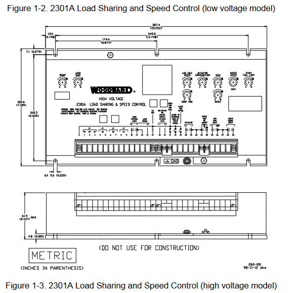
Installation specifications and wiring
1. Installation environment and location requirements
Environmental conditions: working temperature -40-85 ℃ (-40-185 ℉), relative humidity 10% -95% (no condensation); Avoid direct contact with water, vibration sources, and strong electromagnetic interference equipment (such as high-voltage cabinets and high current cables).
Installation restrictions: It is prohibited to install directly on the engine; Reserved heat dissipation space is required (with a ventilation gap of ≥ 3cm and a distance of ≥ 15cm from heating components), and a vertical installation inclination angle of ≤± 45 ° (when there is no forced ventilation).
2. Electrical wiring and shielding requirements
(1) Core interface wiring
The controller terminals are concentrated on the front panel, and the key interfaces and wiring requirements are as follows:
Interface type, terminal number, wiring requirements, precautions
Low voltage power input type (15-, 16+); High voltage type (0, 16) low voltage: 18-40VDC; High voltage: 90-150VDC/88-132VAC requires installation of XT-FIL-1/2 anti-interference filter (mandatory in maritime scenarios); Terminal creepage distance ≥ 6.5mm (compliant with the EU Low Voltage Directive)
Speed sensors 28 (signal+), 29 (signal -), and 27 (shielded) use shielded twisted pair cables. Only one end of the shielding layer is connected to terminal 27, and the other end is suspended with an insulation sensor gap of 0.25-1.0mm. The radial runout of the gear is ≤ 0.5mm
The output of the actuator is 20 (+), 21 (-), and 22 (shielding), and the shielding layer is only connected to terminal 22. It is forbidden to connect the actuator or other grounded actuators. The coil resistance is about 35 Ω, and open/short circuits need to be checked
Load sensor (CT/PT) CT (4-9), PT (1-3) CT secondary output 3-7A (rated 5A), PT secondary 100-120VAC/200-240VAC CT open circuit will generate high voltage, short circuit or power off before wiring
Load distribution lines 10 (+), 11 (-), and 12 (shielded) are shielded twisted pair cables. When multiple units are connected in parallel, the shielding layer is continuously connected without the need for additional relays. The controller is equipped with a built-in load distribution relay
(2) Shielding and anti-interference
All signal cables (speed measurement, actuator, load distribution lines) must use shielded twisted pair cables, with the shielding layer only grounded at the controller end (terminals 22, 27, 12) and the other end suspended to avoid the formation of ground current.
- OMRON
- ABB
- General Electric
- EMERSON
- Honeywell
- HIMA
- ALSTOM
- Rolls-Royce
- MOTOROLA
- Rockwell
- Siemens
- Woodward
- YOKOGAWA
- FOXBORO
- KOLLMORGEN
- MOOG
- KB
- YAMAHA
- BENDER
- TEKTRONIX
- Westinghouse
- AMAT
- AB
- XYCOM
- Yaskawa
- B&R
- Schneider
- KONGSBERG
- NI
- WATLOW
- ProSoft
- SEW
- ADVANCED
- Reliance
- TRICONEX
- METSO
- MAN
- Advantest
- STUDER
- DANAHER MOTION
- Bently
- Galil
- EATON
- MOLEX
- DEIF
- B&W
- ZYGO
- Aerotech
- DANFOSS
- Beijer
- Moxa
- Rexroth
- Johnson
- WAGO
- TOSHIBA
- BMCM
- SMC
- HITACHI
- HIRSCHMANN
- Application field
- XP POWER
- CTI
- TRICON
- STOBER
- Thinklogical
- Horner Automation
- Meggitt
- Fanuc
- Baldor
- SHINKAWA
- Other Brands
- UniOP
- KUKA
- Iba
- Beckhoff
-
 OMRON C60H C6DR DE V1 Sysmac PLC
 -
 MITSUBISHI ELECTRIC A2ACPU21 S1 CPU Module
 -
 ABB BAILEY INNPM12 Network Process Module
 -
 HONEYWELL 620 0073C IPC PLC Module
 -
 Mitsubishi 15050 PR02B PLC Circuit Board
 -
 SIEMENS 6SY7000 0AC37 Drive Control Module
 -
 OMRON TJ2 ECT16 Traxial EtherCAT Controller
 -
 GE Fanuc IC698PSD300D Power Supply Module
 -
 Texas Instruments Series 505 16 Position Base
 -
 OMRON YASKAWA SGDH 10DE OY Servo Drive
 -
 Allen‑Bradley 440G-MT Safety Interlock Switch Specs
 -
 Rubycon PD27A 24V 8A Power Supply Module
 -
 SK-H1-GDB1-F11D PLC Gate Driver Board Kit
 -
 VIPA 441-4UA14 451-4UA14 PLC Module Rack
 -
 Mitsubishi FX5U-80MT ESS PLC Controller Specs
 -
 Mitsubishi Q64TCRTN Temperature PLC Module
 -
 GE 1C31170G Rev10 PLC Circuit Board Module
 -
 Schneider TWDLMDA40DTK PLC Controller Module
 -
 Omron FQM1-MMA22 Motion Control Module Specs
 -
 OMRON CJ1W-NCF71 Position Control Unit Specs
 -
 Schneider TSXETY4103 Ethernet Module
 -
 Mitsubishi Q12PHCPU Process CPU
 -
 Yaskawa 3G3HV-A4022-CE AC Drive
 -
 Cincinnati Milacron 3-533-0669G Temperature Control Board
 -
 Allen Bradley 20AC030A3AYNANC0 PowerFlex 70 Drive
 -
 Siemens 6ES7314-6BG03-0AB0 CPU 314C-2 DP
 -
 Carrier 17EX54007903 PLC Module
 -
 OMRON CS1W-V600C12 ID Controller Module
 -
 Honeywell 51402755-100 PCB Card
 -
 Heidenhain ECN 113 Rotary Encoder
 -
 OMRON B7AM-8B16 I/O Terminal Block
 -
 Fanuc A06B-6110-H026 Power Supply Module
 -
 Schneider TSXETG3021 Ethernet Gateway
 -
 OMRON CS1W-CLK21-V1 Controller Link Unit
 -
 NP1W6406T-Z704 PLC I/O Module
 -
 OMRON CJ1W-DA08C Analog Output Module
 -
 Yaskawa 3G3HV-A4022-CE AC Drive
 -
 OMRON NB7W-TW01B CP1L-EL20DR-D Power Panel
 -
 OMRON C500-NC103-E Position Control Unit
 -
 Steag Hamatech PLC DCS Servo Control System
 -
 Siemens 6SN1123-1AA00-0DA1 Power Supply Module
 -
 GE IC693CHS391H CPU & AD693CMM301A PLC Module
 -
 Siemens 6FC5303-0AF23-1AA1 PLC Control Panel
 -
 Square D CM4000T PowerLogic Circuit Monitor J1 F16
 -
 Siemens 6FX5002-5DG10-1BA0 MOTION-CONNECT 500 Cable
 -
 Schmersal SRB324ST 101195504 Safety Relay 24V
 -
 Mitsubishi 15050-PR02A PLC Circuit Board Module
 -
 OMRON CQM1-AD041 Analog Input PLC Module
 -
 Beckhoff EL5042 EtherCAT PLC Terminal Module
 -
 OMRON C200HW-MC402-E Motion Control Unit
 -
 C36TC0UA1100 Industrial Temperature Controller
 -
 NL8048BC24 12 Industrial Control LCD Module
 -
 OMRON R88D Servo Drive and Motor System
 -
 OMRON CS1W CLK21 V1 Controller Link Module
 -
 OMRON YASKAWA R7M A20030 S1 D Servo Motor
 -
 SIEMENS 6AV2128 3KB06 0AX1 Unified Comfort Panel
 -
 Schneider Electric METSEPM8240 PowerLogic Meter
 -
 Advanced AMCI 1PLC 1 31F Programmable Limit Switch
 -
 ABB PM582 ETH Programmable Logic Processor
 -
 SIEMENS 6FC5110 0CB01 0AA0 CPU Control Board
 -
 Schleicher P03GS13A CPU Module
 -
 Siemens 6SN1123-1AA00-0BA1 Power Module
 -
 Mitsubishi A1S61PN Power Supply Module
 -
 Yaskawa CPS-IONB DC Power Supply Module
 -
 Siemens 6ES7215-2BD00 CPU 215-2
 -
 Mitsubishi A2ACPU MELSEC PLC System Kit
 -
 ProSoft 3150-MCM Communication Module
 -
 Mitsubishi OSE104ET Incremental Encoder
 -
 OMRON CJ1W-AD081-V1 Analog Input Module
 -
 Broadcom BCM5464A1KRB Quad Port Ethernet IC
 -
 Modicon M221-24IO TM221C24 PLC 24 PNP Transistor
 -
 Allen-Bradley 1321-3R160-B Line Reactor 3R160B
 -
 Beckhoff CX1020-0012 Embedded PLC Module Specs
 -
 Turck BL20-PF-24VDC-D Power Feed Module Specs
 -
 Siemens 6SY7000-0AC37 Power Supply Module
 -
 Yaskawa SGDH-10DE-OY 1kW 400V Servo Drive Specs
 -
 Omron 3G3SV-BB015-E 1.5kW 220V VFD Specs
 -
 Uni-Pro CPU91-PLC J 23.020167X Processor Module
 -
 PASABAN MTC-3044 PLC Rack Power Supply 4835-A
 -
 XYCOM 3015T Operator Interface Panel BIN4.4.4
 -
 OMRON CJ1W-MD261 Mixed I/O Module
 -
 Omron NJ301-1100 PLC CPU eCat EIP Specs
 -
 Omron F500-C15-ETN Vision System PLC Module
 -
 Modicon M241-24IO TM/T2UK PLC with Ethernet
 -
 SIXNET YS-800-001 RTU PLC Module
 -
 BEMAC UST-202-D Interface Board 1307D V08B2
 -
 Yaskawa JANCD-MMOIC-02 Drive Circuit Board
 -
 ABB 3BSE005028R1 SDCS-COM-1 Comm Board
 -
 Omron 3G3MX2-A4110 A4150 Inverter Drives Specs
 -
 KEYENCE CA-E100 PLC Module
 -
 GE IC693ALG223-GB Analog Input Module Specs
 -
 ABB BAILEY IMMFP01 Multi Function Processor System
 -
 SIEMENS 6FC5372 0AA00 0AA1 NCU 7202 Controller
 -
Modicon TM241CE4 40I O Transistor Programmable Controller
-
 SIEMENS 6ES7 315 2EH13 0AB0 CPU 3152 PN DP
 -
 NORIS A1 91 PCB Card Rack Module System
 -
 SIEMENS 6ES7 313 5BE01 0AB0 Compact CPU
 -
 SCHNEIDER ELECTRIC S144B MICROLOGIC 60A Trip Unit
 -
 CNI PLC269 v3 Control Module Board Rev H
 -
ABB BAILEY IIMCP02 Processor Module
-
 OMRON NT20S ST121 EV3 Operator Interface Terminal
 -
 OMRON NS-CA001 Video Input Unit
 -
 GE Fanuc IC695CHS012 RX3i Backplane
 -
 Allen Bradley 2711E-K14C6 PanelView 1400e Terminal
 -
 Siemens Sinamics CCB 10000432.71 Power Cell
 -
 Siemens 6SL3210-1SE21-8UA0 Power Module PM340
 -
 Yaskawa CIMR-F7A20P4 AC Drive
 -
 Beckhoff EP1918-0002 EtherCAT Box I/O Module
 -
 OMRON CQM1-TC001 Temperature Control Module
 -
 GE Fanuc SGHA36AT0400 Industrial Contactor
 -
 OMRON NJ501-1500 PLC Machine Automation Controller
 -
 Mitsubishi MAZAK QX084 Power Supply MELDAS 500 CNC
 -
 B&R 0AC808.9 PLC Automation Module
 -
 OMRON CP1H-XA40DT1-D PLC Module
 -
 G&W Electric PLC15 5111 011 15kV Capnut Assembly
 -
 GE DS200SLCCG3AGH PCB Circuit Board
 -
 Siemens SINUMERIK 6FC3981-4FD PLC Extension
 -
 OMRON F300-DC I/O Image Processing Unit
 -
 FANUC A06B-0314-B002 AC Servo Motor
 -
 GC-S84 Programmable Controller Logic Module
 -
 PASABAN MONTELEC MTC3001-DC Drive Control PLC
 -
 Allen Bradley 100E460EJ11 Auxiliary Contactor
 -
 Bosch Rexroth 1070075337-101 Card Parameters
 -
 HMS Anybus AB7646-F Gateway Specifications
 -
 Bosch 062633-303401 CNC Servo PLC Card
 -
 TI 500-5023 Series PLC Power Supply
 -
 Siemens C98043-A7002-L1-12 Circuit Board
 -
 Omron E5CC-RX3A5M-000 Controller


