
Tektronix 4000 series oscilloscope
Tektronix 4000 series oscilloscope
Introduction to Tektronix 4000 Series (Basic Function Demonstration)
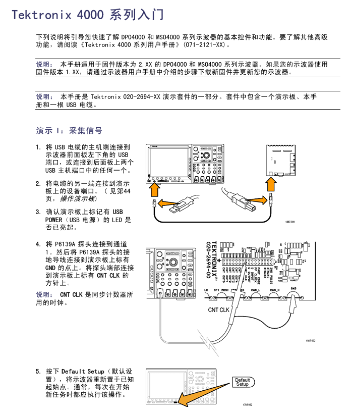
1. Demo I: Collecting Signals
Step: ① Connect the oscilloscope (front/rear panel USB port) to the device port on the demonstration board using a USB cable; ② Confirm that the "USB POWER" LED on the demonstration board is on; ③ P6139A probe (channel 1) is connected to the demonstration board "GND" and "CNT CLK" (synchronous counter clock); ④ Press' Default Setup 'to reset; ⑤ Press' Auto Settings' to display multiple cycle clock signals.
2. Demo II: Using Vertical Controls
Operation: ① Rotate the vertical "scale" knob of channel 1 (observe the change in volts/grid, set to 1 V/grid); ② Rotate the vertical "position" knob (waveform centered); ③ Press the channel 2 button (switch channel 2).
3. Demo III: Using Horizontal Controls
Operation: ① Rotate the horizontal "scale" knob (observe time/grid changes, set to 20 ns/grid); ② Rotate the horizontal "position" knob (adjust the trigger position icon to the center of the screen); ③ Identify the display identifier (yellow bar=all collected, gray square brackets=current display section).
4. Demo IV: Using the Run/Stop Control
Operation: ① Press "Run/Stop" (stop collecting and display the last waveform); ② Press' Single '(stop after collecting a single waveform); ③ Press' Run/Stop 'again (restart collection).
5. Demo V: Using Trigger Controls
Operation: ① Rotate the trigger "position" knob (move it outside the waveform, and the waveform will randomly scroll); ② Press' Force trigger '(display single waveform acquisition); ③ Press' Set to 50% '(trigger level set to signal midpoint, stable trigger).
6. Demo VI: Using the cursor
Step: ① Press the "cursor" button (display vertical cursor, reading includes time/amplitude/increment); ② Use the multifunctional A/B knob to move the cursor (switch fine adjustment mode with the "Fine" button); ③ Measurement cycle (with the cursor placed at the midpoint of two falling edges, with a difference of approximately 100 ns); ④ Press the 'cursor' twice to close.
7. Demo VII: Measurement
Step: ① Press the "Measure" button; ② Click on the 'Select Measurement' button below; ③ Select "cycle" and "frequency"; ④ View readings (including value, average, minimum, maximum, standard deviation, such as frequency of approximately 10.0M); ⑤ Delete measurement ("Delete Measurement" → "Delete All Measurements"); ⑥ Press' Menu Off 'to close the menu.
8. Demo VIII: Saving Screen Images
Step: ① Insert USB/CompactFlash; ② Press' Save/Recall Menu '; ③ Select 'Save Screen Image'; ④ Multi function knob A selects the driver; ⑤ Press' Select '(expand/shrink directory); ⑥ Select file format (such as. png); ⑦ Press' OK to save screen image '; ⑧ Quick save (press the "Save" button, default image saved, can change saved content).
Tektronix 4000 Advanced Feature Demonstration
1. Overall packaging and performance
(1) Overall packaging advantages
10.4-inch XGA large display (high brightness, visually friendly);
Each channel has an independent vertical control knob (no need to select a channel first, efficient and intuitive);
Front and rear USB and CompactFlash ports (convenient for transferring data);
Thickness of 5.4 inches (saving workspace);
Weight 11 pounds (4.99 kilograms), with handle (portable);
Supports 11 languages (including Simplified/Traditional Chinese).
(2) Performance Parameters (Table)
Product Model Bandwidth Channels (DPO/MSO) Maximum Analog Sampling Rate (All Channels) Main Record Length (All Channels) MSO MagniVu Record Length (All Digital Channels)
DPO4104 & MSO4104 1 GHz 4 / 4+16 5 GS/s 10 M 10 K
DPO4054 & MSO4054 500 MHz 4 / 4+16 2.5 GS/s 10 M 10 K
DPO4034 & MSO4034 350 MHz 4 / 4+16 2.5 GS/s 10 M 10 K
DPO4032 & MSO4032 350 MHz 2 / 2+16 2.5 GS/s 10 M 10 K
Additional performance: All channels ≥ 5X oversampling (sin (x)/x interpolation, single full bandwidth); All channels have a record length of 10 meters; Support waveform labels.
2. Wave Inspector Demonstration
(1) Demo IX: Setting I2C Signal
Step: ① P6139A probe (channel 1 → SCLK, channel 2 → I2C SDA, all connected to GND); ② Confirm that the I2C LED is on (press "Serial SELECT" until it lights up); ③ Press' Default Setup '; ④ Trigger the "position" knob to set the trigger level to ≈ 2 V; ⑤ Open channel 2; ⑥ Channel 1/2 vertical "scale" is set at 2.0 V/grid, with positions at the top/middle of the scale respectively; ⑦ Press "Collect" → "Record Length" → "1M Points"; ⑧ Set the horizontal "scale" to 20.0 ms/grid; ⑨ Press' Single 'to display I2C clock (ch1 yellow) and data (ch2 blue).
(2) Demo X: Zoom and Pan Functions
Core control: Wave Inspector "pan/zoom" knob (outer ring=pan, inner ring=zoom);
Operation: ① Turn the zoom knob clockwise (enable zoom, display full capture/current display/zoom view); ② Amplify to a single clock pulse; ③ Translation knob (counterclockwise=left shift zoom box, clockwise=right shift, 10M recording length can be quickly moved); ④ Play/Pause "(automatically scrolling waveforms, adjusting speed/direction by moving the knob); ⑤ Set/Clear "(mark, solid white triangle=bookmark); ⑥ Arrow buttons (navigation markers).
(3) Demo XI: Search Function
Step: ① Press "Search" ->"Search" on the lower bezel ->"Turn on" on the side bezel; ② Clear all tags; ③ Select "Pulse" for "Search Type", select 2 for "Source", and set "Positive" for "Polarity"; ④ The threshold is set to ≈ 2.00 V (midpoint of channel 2 waveform); ⑤ Select "Pulse width<8.00 ns" for "Set marking time" and adjust it to 5 μ s (display hollow triangle mark, event number displayed in the bottom left corner); ⑥ Arrow button navigation markers; ⑦ Zoom in and observe (e.g. 5kX zoom); ⑧ Close search (Search → Close).
3. Serial triggering and analysis
(1) Demo XII: Serial Triggering and Analysis (Using I2C as an Example)
Step: ① Adjust the scaling factor by 50X and pan to the target view; ② Press B1 → "Bus" and select "I2C"; ③ Define Input "(SCLK=Channel 1, SDA=Channel 2); ④ Set the midpoint of the waveform as the "threshold"; ⑤“Menu Off”; ⑥ Zoom observation (green bar=packet start, yellow box=address, cyan box=data, red box=lost confirmation, red bar=stop); ⑦ Switch between "binary/hexadecimal" for "bus display"; ⑧ Event Table "(displays packet timestamps when enabled, similar to a logic analyzer); ⑨ Trigger settings: "Trigger menu" → "Type" select "Bus" → "Signal source bus" select B1 → "Address" set to 50 (hexadecimal), "Direction" set to "Write" → "Single" acquisition → Zoom to view trigger content.
(2) Demo XIII: Searching for Serial Signals (Taking I2C as an Example)
Step: ① "Trigger menu" ->"Type", select "Edge" ->"Single time" collection; ② Select "Bus" for "Search" → "Search Type", choose B1 for "Source Bus"; ③ Select "Start" for "Search" → Arrow button navigation mark; ④ Select "Address" for "Search", set to 76 (hexadecimal) → decrease results; ⑤ Save all tags "(hollow to solid, old tags can be retained).
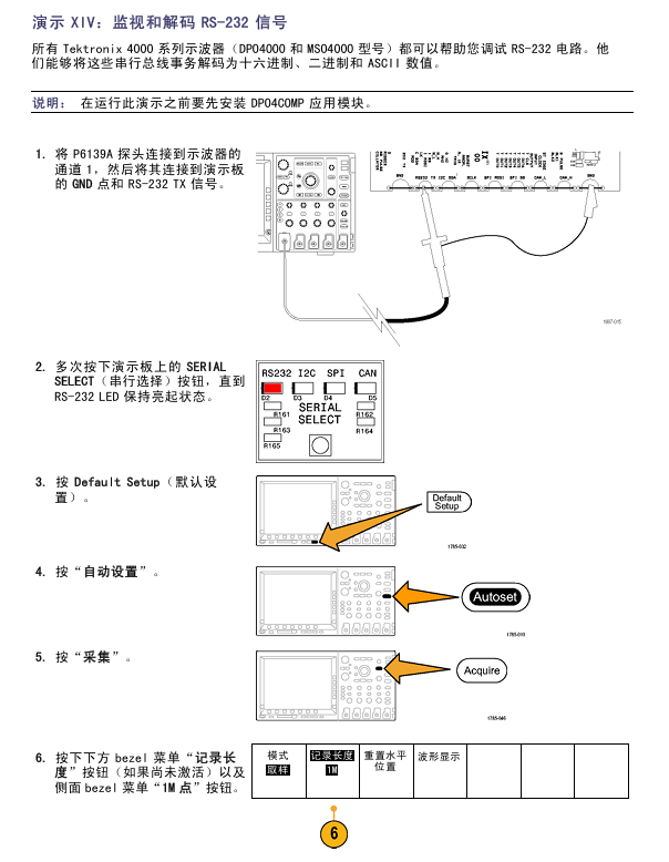
(3) Demo XIV: Monitoring and Decoding RS-232
Prerequisite: Install DPO4COMP application module;
Step: ① P6139A (Channel 1 → RS-232 TX, connected to GND); ② Press' Serial SELECT 'until the RS-232 LED lights up; ③ Default Setup "→" Auto Settings "→" Collection "→" Record Length "=1M points; ④ Set the horizontal "scale" to 20 ms/grid; ⑤ Press B1 → "Bus" and select "RS-232"; ⑥ Define Input "with channel 1 as" Send Input "and" Configure "with a bit rate of 9600; ⑦ Select "ASCII" ->"Single" ->Scale 10X (read characters) for "Bus Display"; ⑧ Play "scrolling messages; ⑨ Event Table "(displaying a list of characters).
(4) Demo XV: Serial Data Pattern Triggering (Using RS-232 as an Example)
Step: ① "Trigger Menu" → "Type" Select "Bus" → "Signal Source Bus" Select RS-232 B1; ② Trigger Open "and select" Send Data "; ③ Set "Data" to 51 (hexadecimal, corresponding to ASCII "Q"); ④ Menu Off "→" Single "; ⑤ Display the word 'Restart' (triggered successfully).
MSO4000 Function Demonstration
1. Core Features
(1) Usability
Wave Inspector supports digital channels (zoom/pan/search/mark);
P6516 digital probe (dual eight channel longitudinal slot, blue coaxial cable identification channel, can be self-made grounding wire);
Color coded display (green=high level, blue=low level, white edge=multiple transitions, gray blur=edge uncertainty).
(2) Performance
16 digital channels (added on the basis of DPO);
MagniVu function (10000 point sampling, 60.6ps timing resolution, 16.5 GS/s sampling rate, switchable main recording/MagniVu recording);
Threshold setting for each channel (supporting multiple logical series);
Supports 4 buses (serial/parallel);
Establish/maintain bus triggering (including 16 digital+4 analog channels, auxiliary input can be expanded to 20 channels);
Parallel bus triggering (user-defined logical mode);
10 M record length (all analog/digital channels);
35000 waveforms per second (analog channel, reducing dead time).
2. Specific demonstration
(1) Demo XVI: Setting up digital channels
Step: ① P6516 probe (D0-D6 → CNT OUT 0-6, D7 → CNT CLK, all grounded); ② Default Setup "→ Close channel 1; ③ Set the horizontal "scale" to 200 ns/grid; ④ Press the blue "D15-D0" button (display digital channel, green=high, blue=low); ⑤ Set "height" to "M" (medium); ⑥ Open D7-D0 "(or separately open D0-D7); ⑦ Select D7 from "Trigger Menu" → "Source" → "Menu Off"; ⑧ Channel grouping: Highlight the group marker (inverted triangle), rotate knob b to move the group waveform.
(2) Demo XVII: Threshold for each channel
Operation: Press the blue "D15-D0" button → follow the "Threshold" button below → use the multifunction knob a/b (group/individual setting of channel threshold voltage).
(3) Demo XVIII: Channel Labels
Step: ① Connect the USB keyboard to the oscilloscope; ② D15-D0 "→" Edit Label "; ③ Set labels (Count 0-6) for D0-D6, and use the preset label "CLOCK" for D7; ④ Menu Off.
(4) Demo XIX: Examining Parallel Buses
Step: ① Press B1 → "Bus" and select "Parallel"; ② Define input → Data bits=7 (D0=LSB, D6=MSB); ③ Set "timer data" to "yes", "clock edge"=rising edge, "clock"=D7; ④ "single" acquisition (clock rising edge decoding bus); ⑤ Event Table "(displays data values and timestamps when enabled, can export CSV).
(5) Demo XX: Parallel bus data value triggering
Steps: ① "Trigger Menu" → "Type" Select "Bus" → "Signal Source Bus" Select B1; ② "Data" Set 7F (hexadecimal, all 1s); ③ Menu Off "→" Run/Stop "; ④ Triggered when 7F occurs.
(6) Demo XXI: Searching for Parallel Bus Data Values
Step: ① Press "Search" → "Open"; ② Copy trigger settings to search "(using 7F from demonstration XX as a standard); ③ Change 'data' to 7X (X=any value, resulting in an increase in results); ④ Menu Off.
(7) Demo XXII: Discovery of multi-channel establishment and maintenance
Step: ① P6516 (D2 → Q OUTPUT, D1 → D INPUT, D0 → FF CLOCK, grounded); ② Default Setup "→ Close channel 1; ③ Open D0-D2, label D0="CLOCK"; ④ Set the horizontal "scale" to 1 ns/grid; ⑤ Select "Create&Maintain" from "Trigger Menu" ->"Type"; ⑥ Define input "(clock=D0, D1/D2=data, clock edge=rising edge); ⑦ Set the establishment time to 500 ps and the holding time to 1.5 ns for "time"; ⑧ "single" acquisition (display timing changes, gray fuzzy band=edge uncertainty); ⑨ MagniVu is enabled (to verify if it is a genuine violation).
(8) Demo XXIII: Magnify the white edge
Steps: ① P6139A (channel 1 → XTALK 1, connected to GND), P6516 (D0 → XTALK 1); ② Default Setup "→" Collection "→" Record Length "=1M points; ③ Press "D15-D0" → "Height" to set "L" (large); ④ Set "Auto Settings" → Horizontal "Scale" to 1 μ s; ⑤ Place channel 1 in the upper half and digital channel in the lower half; ⑥ Run/Stop "(observe the white vertical edge); ⑦ Pan/zoom to white edge → zoom in (view narrow pulse details).
Demo board operation and troubleshooting
1. Operation demonstration board
Serial Select button: Switch serial standards (RS232, I2C, SPI, CAN), corresponding LED lights up;
Random Errors button: Generate a random error signal (burr frequency 1-10 ns, duration 500 ns-50 μ s);
SINGLE/HOT ON/OFF button: Switch between single/continuous serial streams;
Single Shot trigger button: Activate 2 ns pulse and 512 MHz oscillator.
2. Troubleshooting of demonstration board
(1) Basic inspection
Power check: Check if the "USB POWER" LED is on. If it is not on, unplug and plug in the USB again;
Set up check: Confirm that the Serial Select LED is consistent with the expected serial standard.
(2) Reset operation
Normal reset: Press the "Reset" button on the demonstration board;
Overall reset: ① Press and hold "SINGLE/HOT ON/OFF"; ② Press and release 'Reset'; ③ Release after all 4 LEDs of Serial Select are fully lit; ④ Four LEDs flash several times, but only the I2C LED lights up (reset completed).
- OMRON
- ABB
- General Electric
- EMERSON
- Honeywell
- HIMA
- ALSTOM
- Rolls-Royce
- MOTOROLA
- Rockwell
- Siemens
- Woodward
- YOKOGAWA
- FOXBORO
- KOLLMORGEN
- MOOG
- KB
- YAMAHA
- BENDER
- TEKTRONIX
- Westinghouse
- AMAT
- AB
- XYCOM
- Yaskawa
- B&R
- Schneider
- KONGSBERG
- NI
- WATLOW
- ProSoft
- SEW
- ADVANCED
- Reliance
- TRICONEX
- METSO
- MAN
- Advantest
- STUDER
- DANAHER MOTION
- Bently
- Galil
- EATON
- MOLEX
- DEIF
- B&W
- ZYGO
- Aerotech
- DANFOSS
- Beijer
- Moxa
- Rexroth
- Johnson
- WAGO
- TOSHIBA
- BMCM
- SMC
- HITACHI
- HIRSCHMANN
- Application field
- XP POWER
- CTI
- TRICON
- STOBER
- Thinklogical
- Horner Automation
- Meggitt
- Fanuc
- Baldor
- SHINKAWA
- Other Brands
- UniOP
- KUKA
- Iba
- Beckhoff
- ADLINK
-
 Rolls Royce H1111.0204 Ship Main Controller
 -
 Basler Electric BE3-32-3AC Reverse Power Relay 9 1376 00 105
 -
 Basler Electric BE3-25-1A1N4 Synch Check Relay 9319100100
 -
 Basler Electric SR4A-2B15B3A Static Voltage Regulator
 -
 Basler Electric SR4A-2B15B3E Static Voltage Regulator
 -
 Basler Electric 9170818100 Solid State Protective Relay
 -
 Basler Electric AEC63-7 Analog Excitation Controller
 -
 Basler Electric 17483 Auxiliary Module
 -
 Basler Electric BE1-59 Over Voltage Relay
 -
 Basler Electric 21600-101 Control Module
 -
 Basler Electric KR2F Generator Voltage Regulator 9056600100
 -
 Basler BE1-CDS Current Differential System
 -
 Basler Electric CBS 212 Current Boost System 9 2650 00 100
 -
 Basler Electric IFM-150 Firing Circuit Chassis
 -
 Basler Electric BE1-60 Voltage Balance Relay C1F A1P D0C3F
 -
 Basler Electric BE1-32R Power Relay A2E D1R A0N0F
 -
Basler Electric BE1-32R Power Relay A2E D1R A0N0F
-
 Basler Electric 8650C80G01 Isolation Transducer PCB Board
 -
 ETEL EA-P2M-300-4/7.5A-0100-01 AccurET Modular 300 Servo Drive
 -
 Basler Electric 87T Transformer Differential Relay
 -
 Basler Electric BE-6868 Power Transformer 5950007559202
 -
 Basler Electric PRS250 Veri-Sync Relay 9088800102
 -
 Basler Electric SCP-250-G-60 VAR Power Factor Controller
 -
 Basler DECS-150 AVR 1NS2V1N1S Voltage Regulator
 -
 Basler UFOV 260A Under Frequency Overvoltage Module
 -
 Basler MOC2 199 Motor Operated Control – Overview and Setup
 -
 Basler BE3-49R-5K5A1 Temperature Relay – Complete Guide
 -
Basler BE 20035 001 Transformer – Technical Data and Installation
-
 Basler BE 02727 001 Transformer – Specifications and Usage
 -
 Basler BE127 Under Voltage Relay – Features and Application Guide
 -
Basler CBS377 Current Boost System – Complete Technical Guide
-
 Basler BE1-87G P/N 9170818100 Differential Relay – In-Depth Specs
 -
Basler BE1-87G Generator Differential Relay – Technical Overview
-
Basler Electric SR4A2B16 SVR Static Voltage Regulator – Complete Guide
-
 Basler Electric 9261500101 Power Supply Module
 -
 Basler Electric AEM-2020 Analog Expansion Module
 -
Basler Electric DGC-2020 Digital Genset Controller 51BRBNEAH001
-
Basler Electric BE1-59N Ground Fault Overvoltage Relay
-
 Basler Electric BE1-59N-A5E-E1L-N0S1F Neutral Overvoltage Relay
 -
Basler Electric MOC2499 Motor Operator Control Potentiometer 9072300430
-
 Basler Electric BE1-50/51M Overcurrent Relay
 -
 Basler Electric 9148100106 MOC3502 Solid State Relay 250VDC 0.25A
 -
 Basler Electric CBS 212 Current Boost System 9265000100
 -
 Basler Electric 10493002 Control Module
 -
Basler BE1-32R D3E E1R A0N1F Power Relay
-
 Basler SR8A2B15B3A Static Voltage Regulator
 -
 Basler IFM-105 Firing Circuit Chassis 9324100105
 -
Basler SR4A2B05B3A Static Voltage Regulator
-
 Basler BE151G1EB6PB0N0F Protective Relay
 -
Basler BE1-59 Electric Over Voltage Relay
-
 Basler 277 Static Programmable Powerline Carrier Channel
 -
 Basler BE1-32R D1E A1P A0N1F Power Relay
 -
Basler SR4A1B07B3A Static Voltage Regulator
-
 Basler Electric BE1-700 Digital Protective Relay
 -
Basler Electric SR8A-2B01B3A Static Voltage Regulator
-
 Basler Electric SR4A-2B01B3E Static Voltage Regulator
 -
 Basler Electric 9017709102 PC Board
 -
Basler Electric SR4A-2B01B3A Static Voltage Regulator
-
 Basler Electric PRS-250 Veri-Sync Relay
 -
 Basler Electric 9066800102 Excitation Support System
 -
Basler Electric BE1-87G Generator Differential Relay 9 1708 18 100
-
 Basler Electric 36T865-2 BE03752001 Power Supply
 -
 Basler Electric M-300 149D940G02 Power Supply
 -
 Basler Electric ACA2040-25GM 4Mp 25Fps Area Scan Camera
 -
 Basler BE1-87G-S1A-A1C-A0N0 Differential Relay
 -
Basler SR8A-2B06B3E Static Regulator SR8A2B06B3E
-
 Basler SCP-210 Frequency Controller 9095400100
 -
 Basler BE1-59-A3E-A1J-N1N3F Overvoltage Relay BE159A3EA1JN1N3F
 -
Basler 9 2011 11 100 Bracket Mounted Terminal Unit
-
Basler 9 1606 00 101 Voltage Regulator
-
 Basler CBS-377 Current Boost System 9109600102
 -
 Basler 8650C72 Exciter Control Module PCB Rev 5
 -
 Basler C2EE1PA0N1F BE1-32R Reverse Power Relay
 -
 ADLINK HPCI-14S12U - Industrial Control Backplane 12PCI Backplane PCI-14S Passive Backplane
 -
-0010.png) ADLINK PCIe-GIE74C - image acquisition card 4-CH GigE Vision PoE+ Frame Grabber
ADLINK PCIe-GIE74C - image acquisition card 4-CH GigE Vision PoE+ Frame Grabber -
-0010_1.png) ADLINK PCI-8164 - control card 4-Axis Advanced Motion Controller Board
ADLINK PCI-8164 - control card 4-Axis Advanced Motion Controller Board -
 ADLINK PCIe-U304 - 4 Port USB3 PCIe Frame Grabbers USB Screw Hole Card
 -
 ADLINK PCI-9112 - Multi-Function Data Acquisition Card DAQ Card
 -
 ADLINK PCI-7432 - 51-12013-0A50 4-CH Isolated Numérique I/O PCI Cartes Digital I/O Card
 -
 ADLINK PCA-6106P3-0C1 REV.C1 - backplane 6-Slot Passive Backplane Board
 -
 ADLINK PCI-7224 - 24-CH Opto-Isolated Digital I/O PCI Board
 -
 ADLINK CPCI-7433R(G) - Digital Input Board Rear I/O CompactPCI Card
 -
 ADLINK EBP-13E4 - 51-46703-0A30 Industrial PC Backplane Passive Backplane
 -
 ADLINK PCIE-HDV62 - Image acquisition card High Definition Video Frame Grabber
 -
 ADLINK EBP-13E4 - 51-46703-0A30 Industrial Backplane Board Passive Backplane
 -
 ADLINK 90111-B1 / CPCI-6770 - PCB CPU MODULE CompactPCI Single Board Computer
 -
 ADLINK PCI-7248 - DATA ACQUISITION PCI CARD 48-CH Parallel Digital I/O Board
 -
 ADLINK PCI-7230 - 51-12003-0a50 board PCI7230 32-CH Isolated Digital I/O Card
 -
 ADLINK PCI2A000CB - 51-20000-0B30 Multi-Function DAQ Card Baseboard
 -
 ADLINK PCI-8134-005 - 4-Axis Motion Controller Card
 -
 ADLINK PCI-7224 - 24-CH Opto-Isolated Digital I/O PCI Card
 -
 ADLINK PCI-7434 - 64-CH Isolated Digital Output Card
 -
 ADLINK PCI-8132 - motion control card 2-Axis Servo & Stepper Controller
 -
 ADLINK PCI-8134 - Motion Controller PCI Card 4-Axis Controller Board
 -
 ADLINK PCI-8164 - Motion Control Card 51-12406-0A40 4-Axis Controller
 -
 ADLINK 51-12001-0C20 - Circuit Board Data Acquisition Interface Module Hardware
 -
 ADLINK NuPR0-840 - industrial control motherboard Full-Size PICMG CPU Board
 -
 ADLINK PCI-7444 - 51-12023-0A10 card 128-CH Isolated Digital Output Board
 -
 ADLINK PCI-1612B - data acquisition card 4-Port RS-232/422/485 Serial Communication Card
 -
 ADLINK PCI-6208V 009 - 8/16-CH 16-Bit Analog Output Cards PCB-I-E-482=6BX3
 -
 ADLINK NUPRO-935A/LV - industrial control motherboard Full-Size PICMG SBC Board
 -
 ADLINK PCI-9114DG - Multi-Function DAQ Card Data Acquisition PCI Card
 -
 ADLINK ACL-7130 - Data acquisition card Isolated Digital I/O Board
 -
 ADLINK ABX-6300D-4E1-BP - board ABX6300D4E1BP Video Interface Expansion Card
 -
 ADLINK CPCI-6940 - CPCI-6940/D1539/M16-0(EA)-000E 6U CompactPCI Processor Board
 -
 ADLINK NuPRO-760 - industrial control motherboard Half-Size PICMG SBC CPU Board
 -
 ADLINK IMB-M42H (G)-0020 - industrial control motherboard LGA1155 Micro-ATX Mainboard
 -
 ADLINK RTV-24 / PCI-MP4S - 51-12519-1C30 4-Channel Real Time Video Capture Board
 -
 ADLINK PCI-8134 - 4-Axis Servo & Stepper Motion Controller Card
 -
 ADLINK MXC-6101D - V.PC000.002.ST.00 Box PC Configurable Embedded Computer
 -
.png) ADLINK PCI-8134A - 51-12421-0A10 Motion Control Card 4-Axis Controller Card
ADLINK PCI-8134A - 51-12421-0A10 Motion Control Card 4-Axis Controller Card -
 ADLINK DIN-100S / DIN-100SA1 - Technology SCSI-II TB 100-PIN Terminal Block Board
 -
.png) ADLINK DIN-812M001 / DIN812M001 - 51-14034-0A1 51140340A1 Terminal Module Breakout Interface
ADLINK DIN-812M001 / DIN812M001 - 51-14034-0A1 51140340A1 Terminal Module Breakout Interface -
_1.png) ADLINK PCI-8164 - Servo motion control 4-Axis Advanced Controller Card
ADLINK PCI-8164 - Servo motion control 4-Axis Advanced Controller Card -
 ADLINK PCIe-GIE64 - Acquisition card GigE Vision PoE+ Frame Grabber
 -
 ADLINK M-302 - Industrial control motherboard ATX PC Board Mainboard
 -
 ADLINK PCI-8134 - Motion Controller PCI Card 4-Axis Controller Board
 -
 ADLINK PCI-RTV24 - Image capture card Analog Video Frame Grabber
 -
 ADLINK PCI-8102 - Motion control card 2-Axis Servo & Stepper Controller Board
 -
 ADLINK PCI-9112 REV.B1 - Card Multi-Function Data Acquisition Card
 -
 ADLINK HSI-DI32-M-N / HSL-TB32-M-DIN - Discrete I/O MODULE Distributed Automation Module System
 -
 ADLINK PCI-7296 - IO card REV.A3 96-CH Parallel Digital I/O Card
 -
-0020.png) ADLINK DIN-814P-A4 / 814Y - terminal board Motion Control Interface Block
ADLINK DIN-814P-A4 / 814Y - terminal board Motion Control Interface Block -
 ADLINK DIN-814P-A4 - 51-14056-0A10 PCB-I-E-2736=ZA01 Screw Terminal Board Breakout
 -
 ADLINK M-322 - motherboard Industrial Control Computer Mainboard
 -
 ADLINK NUPRO-406 REV:B1 - industrial control motherboard Full-Size PICMG CPU Board
 -
 ADLINK AMP-204C - card DSP-Based 4-Axis Advanced Pulse-Train Controller
 -
 ADLINK HPCI14S REV.B1 - industrial computer baseboard 14-Slot Passive Backplane


