
TEKTRONIX 4K/UHD Monitoring and Measurement Guidelines
TEKTRONIX 4K/UHD Monitoring and Measurement Guidelines
Background and 4K/UHD basic specifications
Tektronix's "4K/UHD Content Creation Guide" aims to address the technical pain points throughout the entire process of 4K/UHD content acquisition, storage, post production, and transmission. The core focus is on "how to ensure signal compliance and content quality through professional monitoring tools", and it is recommended to use Tektronix 8000 series waveform monitors/rasterizers as the core equipment.
4K/UHD core specifications
Category Details Key Parameters
Resolution movie level 4096 × 2160 pixels
Home grade (UHDTV1) 3840 × 2160 pixels
Enhanced technology with dynamic range support for HDR (high dynamic range) to enhance light and dark details
Color gamut supports ITU-R BT.2020 wide color gamut (wider coverage than BT.709)
Signal transmission high frame rate (50p/59.94p/60p) four link 3G-SDI
Low frame rate (23.98p-30p) HD-SDI
6 Core Challenges in 4K/UHD Content Creation
Challenge 1: Inter channel timing synchronization of Quad Link signals
The four link 4K/UHD signal consists of four independent SDI physical links. Due to differences in transmission paths (cable length, equipment delay), timing deviations are prone to occur, resulting in signal splicing errors.
Standard requirements:
According to SMPTE ST 425-5 standard, the inter channel delay at the output end of the device should be ≤ 400ns (approximately 29 clock cycles);
There is no unified standard for the receiving end, and users need to control the delay difference themselves. Tek 8000 series devices can tolerate a maximum of 1024 clock differences.
Monitoring and investigation:
Using Tek 8000 series patented Timing Display, compare the horizontal/vertical offset of Link B/C/D with Link A as a reference;
If a "Video Format Mismatch" error occurs, switch to "Single Link" mode and check if the formats (resolution, frame rate) of each link are consistent;
Check the specific delay value through "MEAS>Timing Display" and adjust the transmission path (such as replacing equal length cables).
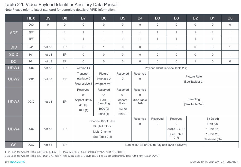
Challenge 2: Video Payload Identifier (VPID) Monitoring
VPID (based on SMPTE ST 352 standard) is stored in the auxiliary data area for devices to quickly identify video formats (resolution, sampling rate, number of links, etc.), and is key to 4K/UHD format compatibility.
VPID structure and key fields:
VPID data consists of 5 core components: Ancillary Data Flag(ADF)、Data Identifier(DID=41h)、Secondary Data Identifier(SDID=01h)、 4 user data words (UDW1-4), checksum (CS), where:
Example of UDW Byte Core Function Key Values
UDW1 identification standard and link type 89h=SMPTE ST 425-5 (four link 3G-SDI), C0h=ST 2081-10 (single link 6G-SDI)
UDW2 image frame rate 2h=24/1.001fps, 5h=25fps, Ah=60/1.001fps
UDW3 sampling rate and color gamut 0h=4:2:2 (YCbCr), 2h=4:4:4 (RGB); 0h=BT.709、2h=BT.2020
UDW4 link number 01h=Link A, 41h=Link B, 81h=Link C, C1h=Link D
Monitoring tools and troubleshooting:
Video Session Display: Directly view the UDW1-4 bytes of each link's VPID. Normal four links require UDW1-3 to be consistent, and UDW4 should be 01h/41h/81h/C1h in the order of A → D;
ANC Data Inspector: locates the field/line position of VPID packets (such as Field1/Line9), verifies the checksum (Exp/ACT Chksum must be consistent);
Common problem: Link sequence error (such as Link B/C switching), physical connection needs to be adjusted to make UDW4 conform to the order.
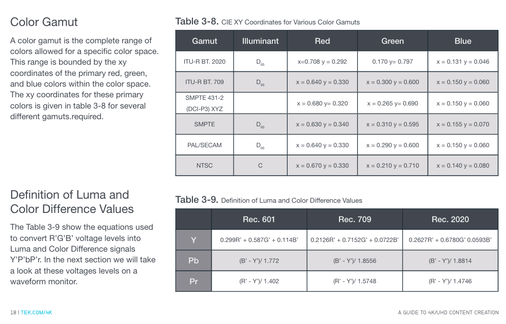
Challenge 3: Choosing the right color gamut
4K/UHD supports ITU-R BT.709 (traditional HD color gamut) and ITU-R BT.2020 (wide color gamut). Choosing the wrong color gamut can result in color distortion, which needs to be matched with content requirements and display devices.
Two major color gamut core differences (CIE 1931 coordinates):
|Color gamut standard | Red (x, y) | Green (x, y) | Blue (x, y) | Applicable scenarios|
|ITU-R BT.709 | (0.640, 0.330) | (0.300, 0.600) | (0.150, 0.060) | Traditional HD, 4K compatible HD content|
|ITU-R BT.2020 | (0.708, 0.292) | (0.170, 0.797) | (0.131, 0.046) | 4K wide color gamut content (such as HDR videos)|
Color gamut conversion and verification:
The difference between brightness (Y) and color difference (Pb/Pr) calculation: The Y formula for BT.2020 is Y=0.2627R '+0.6780G'+0.0593B ', and BT.709 is Y=0.2126R'+0.7152G '+0.0722B';
Verification method: Using 100% split field color bar signals (including BT.709 and BT.2020 dual color gamut), in RGB waveform display, the signal level should be stable at 0% (0mV) and 100% (700mV) under the correct color gamut, without significant fluctuations.
Challenge 4: Determine the aspect ratio of input 4K/UHD content
The aspect ratio of 4K/UHD content varies depending on the application scenario (movies, TV), and it is necessary to verify whether the image is scanned and cropped correctly to avoid stretching or cropping.
Common aspect ratios and corresponding resolutions:
|Aspect ratio | Application scenarios | Image size (pixels) | Effective pixels/line|
|16:9 (1.778:1) | UHDTV1 (Home) | 3840 × 2160 | 3840 pixels/2160 rows|
|1.896:1 | 4K Movie (Standard) | 4096 × 2160 | 4096 pixels/2160 lines|
|1.85:1 | widescreen movie | 3996 × 2160 | 3996 pixels/2160 lines (first line 83, last line 2242)|
|2.39:1 | Ultra widescreen movie | 4096 × 1716 | 4096 pixels/1716 lines|
Verification steps:
Vertical direction: Use the "Line Select" mode to check the effective signals of the first row (such as row 83 corresponding to 1.85:1) and the last row (row 2242);
Horizontal direction: Display with "Datalist", check the first pixel (such as sample 50 corresponding to 1.85:1) and the last pixel (sample 4045) to ensure that the image is not cropped.
Challenge 5: Meet the high-quality requirements of 4K/UHD content
4K/UHD viewers have higher expectations for image quality and need to monitor brightness, color gamut, audio volume, etc. through strict quality control (QC) to ensure compliance and not disrupt artistic intent.
Core monitoring dimensions of QC:
|Monitoring Type | Standard/Threshold | Tool Configuration|
|Video color gamut | RGB color gamut: Set diamond area threshold (such as 1% deviation alarm); Brightness: -230mV~120IRE | Tek 8000 series "Gamut Thresholds" menu, supports EBU-R103 preset|
|Audio loudness | Compliant with EBU R128 (target -23 LKFS), ITU-R BS.1770 | "Loudness Settings" menu, set alarm threshold (such as ± 2 LU deviation)|
|Signal error | Freeze frame, black field detection, SDI link error | "Alarms" menu, enable screen prompts, logging, and beep alarms|
Error recording and tracing:
Record error types (such as "RGB Gamut Error") in the associated timecode (e.g. 00:08:16:02);
The error log can be downloaded as a file and sent to the post production team along with the content to quickly locate the problem frame.
Challenge 6: Selection of Transmission Methods for 4K/UHD Signals
The four link signal needs to go through the "splitting transmission reassembly" process, with two mainstream splitting modes that match the transmission protocol supported by the device.
Comparison of two transmission modes:
|Transmission mode | Split logic | Advantages | Applicable scenarios|
|Square Division | Divide 4K images into 4 quadrants (Link A=upper left, B=upper right, C=lower left, D=lower right), each quadrant packaged as an independent SDI | Simple logic, easy to reorganize | Post production equipment (such as editing machines, color palettes)|
|Two Sample Interleave | Split by horizontal pixel groups: every 2 adjacent pixels are grouped and allocated to 4 links (such as pixel 0/4/8 → Link A, 1/5/9 → Link B) | Low memory usage, high transmission efficiency | Signal transmission links (such as broadcasting networks, satellite transmission)|
Mode configuration and validation:
Tek 8000 series: automatically recognizes VPID and standard recognition mode, or manually selects "Tile" or "Sample Interleaved" in "CONFIG MENU>Quad SDI Mode";
Verification: Confirm through image display (Rasterizer) that there is no misalignment after recombination (such as no black edges, no pixel offset).
Recommended monitoring tools and reference resources
1. Tektronix core equipment
Equipment series types, core functions, applicable scenarios
WFM8000 waveform monitor for high-precision measurement (timing, color gamut, VPID), supporting four link synchronous monitoring signal acquisition, engineering testing, and main control room
WVR8000 waveform grating instrument image display+waveform monitoring, supporting 4K/UHDTV1, including quality alarm content creation (post production, color grading), and content distribution
2. Reference standards and resources
Timing: SMPTE ST 425-5 (four link timing) SMPTE ST 352(VPID);
Color gamut: ITU-R BT.709, ITU-R BT.2020;
Loudness: EBU R128, ITU-R BS.1770;
Key issues
Question 1: How to troubleshoot channel timing deviation issues using Tektronix 8000 series devices in four link 4K/UHD signal transmission? Please refer to the standard requirements and operating procedure instructions.
Answer: Four link timing deviation needs to be checked according to SMPTE ST 425-5 standard (device output delay ≤ 400ns). The Tek 8000 series operation steps are as follows:
Preliminary check for link format consistency:
If the status bar displays "Video Format Mismatch", switch to "Single Link" mode, open the "Video Session" display, confirm that the resolution (such as 3840 × 2160), frame rate (such as 59.94p), and sampling rate (such as 4:2:2) of Link A/B/C/D are completely consistent, and eliminate timing misjudgments caused by format differences;
Enable Timing Display to monitor latency:
Go to "MEAS>Timing Display" and use Link A as a reference (default) to check the "Horizontal Offset" and "Vertical Offset" of Link B/C/D relative to Link A. The Tek 8000 series can tolerate a maximum clock difference of 1024, and if exceeded, it cannot be correctly spliced;
Adjust transmission path:
If the delay of a certain link exceeds the standard, priority should be given to checking the cable length (replacing equal length 3G-SDI cables), followed by investigating the delay differences of intermediate devices (such as switches and distributors), adjusting and re monitoring until the delay of all links is ≤ 400ns;
External reference calibration (optional):
If higher accuracy is required, a black field or three-level reference signal can be connected to the "External Reference" port of the instrument to compare the timing of Link A with the reference signal and further calibrate the link delay.
Question 2: What is the role of VPID (Video Payload Identifier) in 4K/UHD systems? How to verify the correctness of VPID through Tek 8000 series devices, and what are the common errors?
Answer: VPID is based on the SMPTE ST 352 standard and stored in the SDI auxiliary data area. Its core function is to enable devices to quickly recognize video formats (resolution, number of links, sampling rate, color gamut, etc.), avoiding manual configuration errors. It is a "format passport" compatible with multiple 4K/UHD devices.
1、 Steps to verify VPID for Tek 8000 series:
Quick verification of video sessions:
Open the "Video Session" display (Page 1) and view the "352M Payload" field (i.e. UDW1-4 bytes of VPID) for each link:
The four links must meet the following requirements: UDW1-3 (format information) is completely consistent (such as 89h CAh 00h), UDW4 (link number) is 01h → 41h → 81h → C1h according to A → D;
ANC Data Inspector deep validation:
Go to "ANC Data Inspector", filter for "DID/SDID=41/01" (VPID identification), and view:
Checksum (Exp/ACT Chksum): must be consistent, otherwise VPID data will be damaged;
Location information: Normal VPID is located at "Field1/Line9", abnormal location may cause the device to not recognize it;
Datalist locates sample level information:
Based on the "Line" and "Sample" displayed by the ANC Inspector, locate the VPID packet in the "Datalist" and confirm that UDW1-4 bytes have no bit errors (such as stuck bits).
2、 Common VPID errors and reasons:
Link number error: UDW4 is not in the order of A → D (01h/41h/81h/C1h), such as Link B/C exchange, resulting in device splicing image misalignment;
VPID duplication/missing: If there are multiple VPIDs on the same link or if a link does not have a VPID, the device cannot determine the format, resulting in an "unknown format" error message;
Checksum mismatch: Data is damaged during signal transmission, and cable shielding needs to be checked or intermediate equipment (such as SDI distributor) needs to be replaced.
Question 3: How to choose between BT.709 and BT.2020 color gamut in K/UHD content creation? How to verify the correctness of color gamut settings through testing signals with Tek 8000 series devices?
Answer: Color gamut selection needs to be combined with content usage and display device capabilities, and verification relies on standard test signals and professional monitoring tools, as follows:
1、 Color gamut selection principle:
Choose the scene for BT.709:
The content needs to be compatible with traditional HD devices (such as old TVs and HD players);
The production environment does not have BT.2020 display devices (such as the monitor only supporting BT.709) to avoid color deviation in the later stage;
Choose the scene for BT.2020:
4K HDR content (such as movies and high-end TV programs) needs to utilize a wide color gamut to enhance color richness;
The target display device supports BT.2020 (such as 4K HDR TV, professional cinema projection).
2、 Color gamut correctness verification steps (using Tek 8000 series):
Prepare test signal:
Generate a "100% split color bar signal" (left half BT.709, right half BT.2020), ensuring that the signal contains RGB three channel full range levels (0% -100%);
Switching instrument color gamut settings:
Go to "CONFIG MENU>Colorimetry", select "BT.709" and "BT.2020" respectively, and observe the RGB waveform display:
Correct setting: The RGB level of the corresponding half is stable at 0% (0mV) and 100% (700mV) without fluctuations;
Error setting: The RGB level of non corresponding half deviates by 0%/100% (for example, under BT.709 setting, the green level of BT.2020 half is only 80%);
Comparison brightness and color difference formula:
Go to "MEAS>Amplitude>Y" and measure the brightness value:
BT.709:Y=0.2126R'+0.7152G'+0.0722B', The Y value of the white color bar is approximately 700mV;
BT.2020:Y=0.2627R'+0.6780G'+0.0593B', The Y value of the white color bar is approximately 680mV;
If the values match, the color gamut setting is correct, and if the deviation exceeds 5%, it needs to be readjusted.
- OMRON
- ABB
- General Electric
- EMERSON
- Honeywell
- HIMA
- ALSTOM
- Rolls-Royce
- MOTOROLA
- Rockwell
- Siemens
- Woodward
- YOKOGAWA
- FOXBORO
- KOLLMORGEN
- MOOG
- KB
- YAMAHA
- BENDER
- TEKTRONIX
- Westinghouse
- AMAT
- AB
- XYCOM
- Yaskawa
- B&R
- Schneider
- KONGSBERG
- NI
- WATLOW
- ProSoft
- SEW
- ADVANCED
- Reliance
- TRICONEX
- METSO
- MAN
- Advantest
- STUDER
- DANAHER MOTION
- Bently
- Galil
- EATON
- MOLEX
- DEIF
- B&W
- ZYGO
- Aerotech
- DANFOSS
- Beijer
- Moxa
- Rexroth
- Johnson
- WAGO
- TOSHIBA
- BMCM
- SMC
- HITACHI
- HIRSCHMANN
- Application field
- XP POWER
- CTI
- TRICON
- STOBER
- Thinklogical
- Horner Automation
- Meggitt
- Fanuc
- Baldor
- SHINKAWA
- Other Brands
- UniOP
- KUKA
- Iba
- Beckhoff
- ADLINK
-
 Rolls Royce H1111.0204 Ship Main Controller
 -
 Basler Electric BE3-32-3AC Reverse Power Relay 9 1376 00 105
 -
 Basler Electric BE3-25-1A1N4 Synch Check Relay 9319100100
 -
 Basler Electric SR4A-2B15B3A Static Voltage Regulator
 -
 Basler Electric SR4A-2B15B3E Static Voltage Regulator
 -
 Basler Electric 9170818100 Solid State Protective Relay
 -
 Basler Electric AEC63-7 Analog Excitation Controller
 -
 Basler Electric 17483 Auxiliary Module
 -
 Basler Electric BE1-59 Over Voltage Relay
 -
 Basler Electric 21600-101 Control Module
 -
 Basler Electric KR2F Generator Voltage Regulator 9056600100
 -
 Basler BE1-CDS Current Differential System
 -
 Basler Electric CBS 212 Current Boost System 9 2650 00 100
 -
 Basler Electric IFM-150 Firing Circuit Chassis
 -
 Basler Electric BE1-60 Voltage Balance Relay C1F A1P D0C3F
 -
 Basler Electric BE1-32R Power Relay A2E D1R A0N0F
 -
Basler Electric BE1-32R Power Relay A2E D1R A0N0F
-
 Basler Electric 8650C80G01 Isolation Transducer PCB Board
 -
 ETEL EA-P2M-300-4/7.5A-0100-01 AccurET Modular 300 Servo Drive
 -
 Basler Electric 87T Transformer Differential Relay
 -
 Basler Electric BE-6868 Power Transformer 5950007559202
 -
 Basler Electric PRS250 Veri-Sync Relay 9088800102
 -
 Basler Electric SCP-250-G-60 VAR Power Factor Controller
 -
 Basler DECS-150 AVR 1NS2V1N1S Voltage Regulator
 -
 Basler UFOV 260A Under Frequency Overvoltage Module
 -
 Basler MOC2 199 Motor Operated Control – Overview and Setup
 -
 Basler BE3-49R-5K5A1 Temperature Relay – Complete Guide
 -
Basler BE 20035 001 Transformer – Technical Data and Installation
-
 Basler BE 02727 001 Transformer – Specifications and Usage
 -
 Basler BE127 Under Voltage Relay – Features and Application Guide
 -
Basler CBS377 Current Boost System – Complete Technical Guide
-
 Basler BE1-87G P/N 9170818100 Differential Relay – In-Depth Specs
 -
Basler BE1-87G Generator Differential Relay – Technical Overview
-
Basler Electric SR4A2B16 SVR Static Voltage Regulator – Complete Guide
-
 Basler Electric 9261500101 Power Supply Module
 -
 Basler Electric AEM-2020 Analog Expansion Module
 -
Basler Electric DGC-2020 Digital Genset Controller 51BRBNEAH001
-
Basler Electric BE1-59N Ground Fault Overvoltage Relay
-
 Basler Electric BE1-59N-A5E-E1L-N0S1F Neutral Overvoltage Relay
 -
Basler Electric MOC2499 Motor Operator Control Potentiometer 9072300430
-
 Basler Electric BE1-50/51M Overcurrent Relay
 -
 Basler Electric 9148100106 MOC3502 Solid State Relay 250VDC 0.25A
 -
 Basler Electric CBS 212 Current Boost System 9265000100
 -
 Basler Electric 10493002 Control Module
 -
Basler BE1-32R D3E E1R A0N1F Power Relay
-
 Basler SR8A2B15B3A Static Voltage Regulator
 -
 Basler IFM-105 Firing Circuit Chassis 9324100105
 -
Basler SR4A2B05B3A Static Voltage Regulator
-
 Basler BE151G1EB6PB0N0F Protective Relay
 -
Basler BE1-59 Electric Over Voltage Relay
-
 Basler 277 Static Programmable Powerline Carrier Channel
 -
 Basler BE1-32R D1E A1P A0N1F Power Relay
 -
Basler SR4A1B07B3A Static Voltage Regulator
-
 Basler Electric BE1-700 Digital Protective Relay
 -
Basler Electric SR8A-2B01B3A Static Voltage Regulator
-
 Basler Electric SR4A-2B01B3E Static Voltage Regulator
 -
 Basler Electric 9017709102 PC Board
 -
Basler Electric SR4A-2B01B3A Static Voltage Regulator
-
 Basler Electric PRS-250 Veri-Sync Relay
 -
 Basler Electric 9066800102 Excitation Support System
 -
Basler Electric BE1-87G Generator Differential Relay 9 1708 18 100
-
 Basler Electric 36T865-2 BE03752001 Power Supply
 -
 Basler Electric M-300 149D940G02 Power Supply
 -
 Basler Electric ACA2040-25GM 4Mp 25Fps Area Scan Camera
 -
 Basler BE1-87G-S1A-A1C-A0N0 Differential Relay
 -
Basler SR8A-2B06B3E Static Regulator SR8A2B06B3E
-
 Basler SCP-210 Frequency Controller 9095400100
 -
 Basler BE1-59-A3E-A1J-N1N3F Overvoltage Relay BE159A3EA1JN1N3F
 -
Basler 9 2011 11 100 Bracket Mounted Terminal Unit
-
Basler 9 1606 00 101 Voltage Regulator
-
 Basler CBS-377 Current Boost System 9109600102
 -
 Basler 8650C72 Exciter Control Module PCB Rev 5
 -
 Basler C2EE1PA0N1F BE1-32R Reverse Power Relay
 -
 ADLINK HPCI-14S12U - Industrial Control Backplane 12PCI Backplane PCI-14S Passive Backplane
 -
-0010.png) ADLINK PCIe-GIE74C - image acquisition card 4-CH GigE Vision PoE+ Frame Grabber
ADLINK PCIe-GIE74C - image acquisition card 4-CH GigE Vision PoE+ Frame Grabber -
-0010_1.png) ADLINK PCI-8164 - control card 4-Axis Advanced Motion Controller Board
ADLINK PCI-8164 - control card 4-Axis Advanced Motion Controller Board -
 ADLINK PCIe-U304 - 4 Port USB3 PCIe Frame Grabbers USB Screw Hole Card
 -
 ADLINK PCI-9112 - Multi-Function Data Acquisition Card DAQ Card
 -
 ADLINK PCI-7432 - 51-12013-0A50 4-CH Isolated Numérique I/O PCI Cartes Digital I/O Card
 -
 ADLINK PCA-6106P3-0C1 REV.C1 - backplane 6-Slot Passive Backplane Board
 -
 ADLINK PCI-7224 - 24-CH Opto-Isolated Digital I/O PCI Board
 -
 ADLINK CPCI-7433R(G) - Digital Input Board Rear I/O CompactPCI Card
 -
 ADLINK EBP-13E4 - 51-46703-0A30 Industrial PC Backplane Passive Backplane
 -
 ADLINK PCIE-HDV62 - Image acquisition card High Definition Video Frame Grabber
 -
 ADLINK EBP-13E4 - 51-46703-0A30 Industrial Backplane Board Passive Backplane
 -
 ADLINK 90111-B1 / CPCI-6770 - PCB CPU MODULE CompactPCI Single Board Computer
 -
 ADLINK PCI-7248 - DATA ACQUISITION PCI CARD 48-CH Parallel Digital I/O Board
 -
 ADLINK PCI-7230 - 51-12003-0a50 board PCI7230 32-CH Isolated Digital I/O Card
 -
 ADLINK PCI2A000CB - 51-20000-0B30 Multi-Function DAQ Card Baseboard
 -
 ADLINK PCI-8134-005 - 4-Axis Motion Controller Card
 -
 ADLINK PCI-7224 - 24-CH Opto-Isolated Digital I/O PCI Card
 -
 ADLINK PCI-7434 - 64-CH Isolated Digital Output Card
 -
 ADLINK PCI-8132 - motion control card 2-Axis Servo & Stepper Controller
 -
 ADLINK PCI-8134 - Motion Controller PCI Card 4-Axis Controller Board
 -
 ADLINK PCI-8164 - Motion Control Card 51-12406-0A40 4-Axis Controller
 -
 ADLINK 51-12001-0C20 - Circuit Board Data Acquisition Interface Module Hardware
 -
 ADLINK NuPR0-840 - industrial control motherboard Full-Size PICMG CPU Board
 -
 ADLINK PCI-7444 - 51-12023-0A10 card 128-CH Isolated Digital Output Board
 -
 ADLINK PCI-1612B - data acquisition card 4-Port RS-232/422/485 Serial Communication Card
 -
 ADLINK PCI-6208V 009 - 8/16-CH 16-Bit Analog Output Cards PCB-I-E-482=6BX3
 -
 ADLINK NUPRO-935A/LV - industrial control motherboard Full-Size PICMG SBC Board
 -
 ADLINK PCI-9114DG - Multi-Function DAQ Card Data Acquisition PCI Card
 -
 ADLINK ACL-7130 - Data acquisition card Isolated Digital I/O Board
 -
 ADLINK ABX-6300D-4E1-BP - board ABX6300D4E1BP Video Interface Expansion Card
 -
 ADLINK CPCI-6940 - CPCI-6940/D1539/M16-0(EA)-000E 6U CompactPCI Processor Board
 -
 ADLINK NuPRO-760 - industrial control motherboard Half-Size PICMG SBC CPU Board
 -
 ADLINK IMB-M42H (G)-0020 - industrial control motherboard LGA1155 Micro-ATX Mainboard
 -
 ADLINK RTV-24 / PCI-MP4S - 51-12519-1C30 4-Channel Real Time Video Capture Board
 -
 ADLINK PCI-8134 - 4-Axis Servo & Stepper Motion Controller Card
 -
 ADLINK MXC-6101D - V.PC000.002.ST.00 Box PC Configurable Embedded Computer
 -
.png) ADLINK PCI-8134A - 51-12421-0A10 Motion Control Card 4-Axis Controller Card
ADLINK PCI-8134A - 51-12421-0A10 Motion Control Card 4-Axis Controller Card -
 ADLINK DIN-100S / DIN-100SA1 - Technology SCSI-II TB 100-PIN Terminal Block Board
 -
.png) ADLINK DIN-812M001 / DIN812M001 - 51-14034-0A1 51140340A1 Terminal Module Breakout Interface
ADLINK DIN-812M001 / DIN812M001 - 51-14034-0A1 51140340A1 Terminal Module Breakout Interface -
_1.png) ADLINK PCI-8164 - Servo motion control 4-Axis Advanced Controller Card
ADLINK PCI-8164 - Servo motion control 4-Axis Advanced Controller Card -
 ADLINK PCIe-GIE64 - Acquisition card GigE Vision PoE+ Frame Grabber
 -
 ADLINK M-302 - Industrial control motherboard ATX PC Board Mainboard
 -
 ADLINK PCI-8134 - Motion Controller PCI Card 4-Axis Controller Board
 -
 ADLINK PCI-RTV24 - Image capture card Analog Video Frame Grabber
 -
 ADLINK PCI-8102 - Motion control card 2-Axis Servo & Stepper Controller Board
 -
 ADLINK PCI-9112 REV.B1 - Card Multi-Function Data Acquisition Card
 -
 ADLINK HSI-DI32-M-N / HSL-TB32-M-DIN - Discrete I/O MODULE Distributed Automation Module System
 -
 ADLINK PCI-7296 - IO card REV.A3 96-CH Parallel Digital I/O Card
 -
-0020.png) ADLINK DIN-814P-A4 / 814Y - terminal board Motion Control Interface Block
ADLINK DIN-814P-A4 / 814Y - terminal board Motion Control Interface Block -
 ADLINK DIN-814P-A4 - 51-14056-0A10 PCB-I-E-2736=ZA01 Screw Terminal Board Breakout
 -
 ADLINK M-322 - motherboard Industrial Control Computer Mainboard
 -
 ADLINK NUPRO-406 REV:B1 - industrial control motherboard Full-Size PICMG CPU Board
 -
 ADLINK AMP-204C - card DSP-Based 4-Axis Advanced Pulse-Train Controller
 -
 ADLINK HPCI14S REV.B1 - industrial computer baseboard 14-Slot Passive Backplane


