
Woodward 723 Generator Controller
Woodward 723 Generator Controller
Application and Overview
The Woodward 723 generator controller is suitable for various generator application scenarios, including auxiliary generators and diesel electric propulsion in ship systems, as well as islanding mode operation and basic load operation on infinite power grids in power plant systems. It has closed-loop speed control function, equipped with torsion filter and notch (band stop) filter, which can alleviate low-frequency oscillation problems caused by engine, generator inertia and flexible coupling. The controller has three operating modes, namely droop control based on 4-20mA megawatt sensor input or actuator position, synchronous load distribution with soft loading/unloading and automatic generator circuit breaker opening command after engine unloading, and megawatt control with soft loading/unloading and automatic generator circuit breaker opening command after engine unloading.
Hardware specifications
Model and output: The models include 8280-500, 8280-501, 8280-502, and 8280-503, which correspond to different voltages and output types. For example, 8280-500 is a high-voltage control with an actuator output of 0-200mA.
Power supply and power consumption: The power supply has 18-40Vdc (nominal 24 or 32Vdc) and 90-150Vdc (nominal 125Vdc), with a nominal power consumption of 40W.
input/output
Speed signal input: The frequency range of the magneto electric sensor is 400-15000Hz, and the proximity switch is 7.5-1000Hz.
Digital input: 8, 8mA at 24Vdc.
Analog inputs: 4, 4-20mA or 1-5VDC.
Analog output: 3, of which 2 are 4-20mA or 0-1mA (connected to instruments or computers), and 1 is 20-160mA or 4-20mA.
Output of actuator: 1, 20-160mA or 4-20mA.
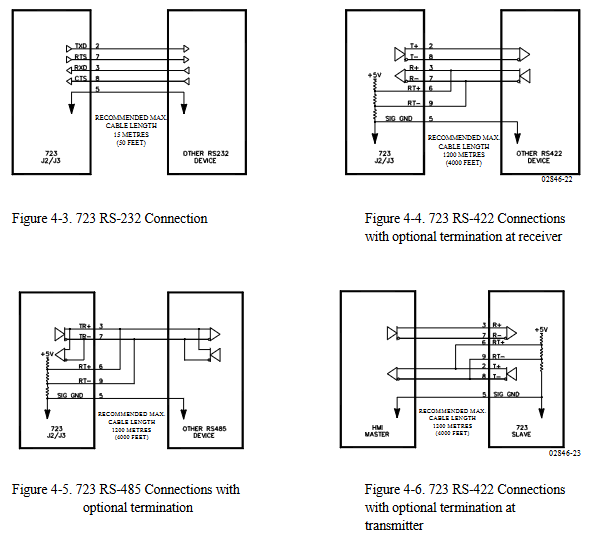
Communication port: The communication port (J1) of the programmer is RS-422, 9-pin D-type connector, 1200 baud rate, full duplex; The communication ports (J2 and J3) are RS-232, RS-422 or RS-485, 9-pin D-type connector, 1200-38400 baud rate, full duplex.
Environmental parameters: working environment temperature -40 to+70 ° C (-40 to+158 ° F), storage temperature -55 to+105 ° C (-67 to+221 ° F), humidity at 38 ° C is 95%, anti electromagnetic interference/radio frequency interference complies with MIL-STD 461C (Parts 5 and 9) in the United States, humidity complies with MIL-STD 810D Method 507.2 Procedure III in the United States, mechanical vibration is a swept sine wave of 24-2000 Hz, constant acceleration of 2.5 Gs, resonance retention -1 million cycles, total time per axis is 3/4-6 hours, mechanical impact complies with MIL-STD 810C Method 526.2 Procedure I (basic design testing), Procedure II (transport drop testing, packaging) in the United States. Program V (Workbench Operation), salt spray complies with ASTM B 117-73.
Key points of installation
Unpacking and Inspection: Before installation, it is necessary to read the relevant content on electrostatic discharge protection. When unpacking, handle the electronic controller carefully and check for any damage. If there is any damage, immediately notify the shipper.
Power requirements: The high-voltage version requires a 90-150Vdc voltage source, and the low-voltage version requires an 18-40Vdc voltage source. Both have a maximum power consumption of 40W and should not exceed the input voltage range. If battery power is used, an AC generator or other battery charging equipment should be equipped.
Location selection: The installation location should consider ventilation, maintenance space, moisture resistance, distance from electromagnetic interference sources, and avoidance of vibration. The working temperature range is -40 to+70 ° C (-40 to+158 ° F), and it cannot be installed on the engine.
Electrical connection: All shielded cables must be twisted pair, and do not attempt to tin plated braided shielding layers. All signal lines should be shielded, and the shielding layer should be connected to the nearest chassis ground. The exposed length of wires outside the shielding layer should be as short as possible, not exceeding 50mm (2 inches). The other end of the shielding layer must be open and insulated from any other conductor. Do not lay the shielded signal line together with other wires carrying high currents.
System function
Engine speed related functions
Speed sensing: The controller has two speed sensing inputs, which can be configured as torsional filtering (to make operation smoother, suitable for flexible couplings) or high signal selection (to achieve speed sensing redundancy, enabled when one signal fails). If a torsion filter is used, the speed sensors should be located on both sides of the coupling; If high signal selection is used, the two speed sensing devices should be located on the same speed measuring disc. Speed sensor # 2 can also be configured to detect the speed of the turbocharger.
Speed filtering: Each speed sensor input has a low-pass filter that can filter out unwanted frequencies on the speed sensor. If tuned above 15.9Hz, the filter will be automatically disabled. In addition, a notch filter can be enabled, and its filtering frequency should be set to the resonance frequency of the velocity signal that needs to be filtered. The filtering Q factor can adjust the attenuation degree of the signal frequency filtered by the band stop filter.
Speed control: including idle speed, rated speed settings, overspeed trip function (starting and stopping when the set speed is reached to prevent overspeed), as well as minimum and maximum speed reference limits and acceleration/deceleration rate control.
Synchronization and load control function
Engine start: When the Run/Stop contact is closed (or configured to be open), the speed reference is at idle. When the engine speed exceeds the idle/rated switching speed, the speed reference will ramp up and down at an acceleration/deceleration rate to the rated speed, which can be interrupted by temporarily closing the deceleration contact. If the idle/rated selection function is enabled, after the engine is started, the idle or ramp to rated speed is determined based on the contact position.
Synchronization function: When the engine reaches the rated speed and maintains the synchronization readiness delay time within the synchronization readiness limit, the "ready synchronization" state is achieved through Modbus ® Convey as True. The speed reference can be adjusted by inputting or adding or subtracting contacts through the unit synchronizer to achieve synchronization with the busbar. Alternatively, after the auxiliary contacts of the generator circuit breaker are closed, the bias speed reference can be input through the system synchronizer to achieve cross busbar connection or synchronization with the grid.
Droop control: When the synchronous/droop contacts are open and the auxiliary contacts of the generator circuit breaker are closed, the following droop modes operate. Calculate the speed droop value based on the droop percentage and engine load. The engine load comes from the input of the megawatt sensor. If the signal fails, it is determined based on the output position of the actuator. At the same time, provide a "droop pulse" function to prevent the engine from sinking into reverse power when connected to the bus in droop mode.
Synchronous load distribution: When the synchronous/droop contacts are closed, and the auxiliary contacts of the generator circuit breaker are closed and the load input signal is normal, synchronous load distribution is enabled. The first online machine immediately closes the relay K4 contact on its load sharing circuit. The subsequently selected synchronous units will adjust the load according to the automatic loading/unloading rate until the load shared with the synchronized units is within the specified load sharing error range. At this point, relay K4 closes to connect to the load sharing circuit and achieve load balancing. It also has an automatic soft unloading function. When the unloading contact is closed (instantaneously), the engine load decreases at an automatic unloading rate to the unloading trip level, and then a command to open the generator circuit breaker is issued.
Megawatt control: When the auxiliary contacts, grid contacts (if used), and megawatt control contacts of the generator circuit breaker are closed and the megawatt load input is not disabled, operate in megawatt control mode. The megawatt reference value can be adjusted by adding or removing contacts, or based on internal megawatt reference or remote reference (4-20mA or Modbus) ®) Adjustment. If the remote reference input fails, the megawatt reference will lock the last healthy value.
Protection and restriction functions
High/Low Frequency Protection: In megawatt control mode, it can be configured to open the grid and/or generator circuit breakers or switch to droop mode (megawatt coverage function) when the grid frequency is too high or too low.
Limiting functions: including start-up and maximum fuel limiter (limiting excessive fuel supply or flooding during engine start-up), engine shutdown limiter, frequency load limiter (limiting engine load when grid frequency exceeds preset limits during megawatt control), boost air pressure limiter (providing fuel limitation based on 4-20mA boost air pressure input signal), etc.
Load rejection function: When the generator circuit breaker or grid circuit breaker is opened and the load is above a certain level, the load rejection algorithm takes effect, driving the actuator output to zero for a period of time to reduce speed overshoot.
- OMRON
- ABB
- General Electric
- EMERSON
- Honeywell
- HIMA
- ALSTOM
- Rolls-Royce
- MOTOROLA
- Rockwell
- Siemens
- Woodward
- YOKOGAWA
- FOXBORO
- KOLLMORGEN
- MOOG
- KB
- YAMAHA
- BENDER
- TEKTRONIX
- Westinghouse
- AMAT
- AB
- XYCOM
- Yaskawa
- B&R
- Schneider
- KONGSBERG
- NI
- WATLOW
- ProSoft
- SEW
- ADVANCED
- Reliance
- TRICONEX
- METSO
- MAN
- Advantest
- STUDER
- DANAHER MOTION
- Bently
- Galil
- EATON
- MOLEX
- DEIF
- B&W
- ZYGO
- Aerotech
- DANFOSS
- Beijer
- Moxa
- Rexroth
- Johnson
- WAGO
- TOSHIBA
- BMCM
- SMC
- HITACHI
- HIRSCHMANN
- Application field
- XP POWER
- CTI
- TRICON
- STOBER
- Thinklogical
- Horner Automation
- Meggitt
- Fanuc
- Baldor
- SHINKAWA
- Other Brands
- UniOP
- KUKA
- Iba
- Beckhoff
-
 Basler D90 96801 100 PCB Card
 -
 Basler XR2002F Voltage Regulator (110 VAC, 48-480 Hz)
 -
 Basler SR8A-2B14B3A Regulator
 -
 Basler 9561500100 Module
 -
 Basler DECS-400 BE1-11 System
 -
 Basler DECS-100-B15 Excitation Control
 -
 Basler SCP 210 Frequency Controller
 -
 Basler SR4A-2B15B3A Static Voltage Regulator
 -
 Basler BE1-32R Power Relay
 -
 Basler PIA2400-17GM Power Interface Adapter
 -
 Basler MVC 232 Manual Voltage Control Module
 -
 Basler SSR 32-12 Static Voltage Regulator
 -
 Basler 5MW AVR Generator Voltage Regulator
 -
 Basler VR63-4B Voltage Regulator
 -
 Basler DECS-100-A05 AVR for Engine Generator
 -
 Basler DECS-100-B15 Automatic Voltage Regulator
 -
 Basler BE1-32R Directional Power Relay
 -
 Basler BE1-87B Differential Relay
 -
 Basler UFOV 260A Protective Module
 -
 Basler 9-2614-02-100 PCB Rev M
 -
Basler DECS-100-B15 Digital AVR
-
 Basler 9284900103 PS DECS-400N
 -
 Basler D4N3H1U Intertie Protection
 -
 Basler DECS-100-B15 A15 AVR
 -
 Basler KR4F Voltage Regulator
 -
 Basler BE26434 T14 Transformer
 -
 Basler SR8A-2B15B3A Regulator
 -
 Westinghouse 774B472A12 AR Relay
 -
Basler DECS-100-B15 AVR
-
Basler XR2002F Regulator 110V
-
Basler SR125-E Static Regulator
-
 Basler SSR 125-12 Regulator
 -
 Basler MOC2599 Motor Pot
 -
 Basler BE1-DFPR Feeder Relay
 -
 Basler CBS 305 Current Boost
 -
 Basler BE1-25 AutoSync
 -
 Basler MVC 300 Voltage Control
 -
 Basler BE3-25A AutoSync
 -
 Basler KR7FF Static Regulator
 -
 Basler 90-49000-100 Regulator
 -
 Basler 880 kVA Dry Type Transformer Specs
 -
 Basler Electric BE1-25 Sync-Check Relay Specs
 -
 Basler SSR 125-12 Voltage Regulator Specs
 -
 Basler Electric BE1-851 Overcurrent Relay Review
 -
Basler Electric 149D930G02 Control Sub-Assembly
-
 Basler Electric BE1-81O/UT Frequency Relay Specs
 -
 Basler Electric BE1-51/27C Overcurrent Relay
 -
 Basler Electric 149D956G02 Industrial Component
 -
Basler Electric BE1-51A Overcurrent Relay Specs
-
 Basler Electric BE1-40Q Loss of Excitation Relay
 -
 Basler DECS-200 Excitation Control System
 -
 Basler DECS-200 Voltage Regulator 56-277V AC / 125V DC
 -
Basler BE1-87T Transformer Differential Relay
-
 Basler RDP-110-S1 Protection Relay
 -
 Basler BE1-700V Digital Protective Relay
 -
 Basler BE1-951 Overcurrent Protection System
 -
 Basler DECS-300 Digital Excitation Control
 -
 Basler DECS-200 Digital Excitation Control
 -
 Basler DECS-200-1C Excitation Control System
 -
Basler DECS-200-1L Digital Excitation Control
-
 Basler Electric BE1-GPS Generator Protection System
 -
Basler Electric DECS-200-1C Digital Excitation Controller
-
 Basler Electric DECS125-15 Excitation Control with Power Module
 -
 Basler Electric BE1-87G Differential Relay
 -
 Basler Electric BE1-11 Protection System I5A3M2P2N0EA00
 -
Basler Electric DECS-200-1C Excitation Control System
-
Basler Electric BE1-11g Generator Protection Relay
-
Basler Electric DECS 125-15-B2C1 V2.0.9 Excitation Control
-
 Basler Electric BE1-81O/UT3ED1JA7N2F Frequency Relay
 -
Basler Electric BE1-81O/UT3EE1YB7N1F Frequency Relay
-
 Basler Electric DECS-200-1L Digital Excitation Control System
 -
Basler DECS125-15-B2C1 Excitation Control
-
 Basler 9507900205 SSR Retrofit Voltage Regulator
 -
 Basler BE2000E Digital Voltage Regulator
 -
 Basler BE1-GPS Generator Protection System
 -
Basler DECS-250-CN1CN1N Digital Excitation Control
-
 Basler DGC-2020 Genset Controller
 -
 Basler BE1-81O UT3ED1LA7N0F Frequency Relay (Variant)
 -
 Basler BE1-81O UT3EE1YA9S0F Frequency Relay (Variant)
 -
Basler BE1-81O Over/Under Frequency Relay
-
Basler DECS125-15 Digital Excitation Control
-
Basler Electric BE1-951 Overcurrent Protection System
-
 Basler Electric BE1-700V Digital Protective Relay
 -
 Basler Electric APR63-5 Automatic Voltage Regulator
 -
Basler Electric BE1-851 Overcurrent Protection System
-
Basler Electric DECS-250-LN1SN1N Excitation Control
-
 Basler Electric BE1-87T Transformer Differential Relay
 -
Basler Electric DECS-200-1L Excitation Control System
-
 Basler Electric 9310300100 DECS-300 Excitation Control
 -
 Basler Electric SSE-N 125-4.5KW Shunt Exciter Regulator
 -
 Basler Electric DGC-2020HD-5NS1DNSBA Genset Controller
 -
Basler Electric BE1-81-O/UT3EE1JB7N1F Frequency Relay
-
Basler Electric BE1-81T1EE1WA0N1F Frequency Relay
-
 Basler Electric BE1-25M1EA6PN5R1F Sync-Check Relay
 -
 Basler Electric BE1-GPS Generator Protection System
 -
Basler Electric DECS-250-LN1SN1N Excitation Control Rev V
-
 Basler Electric DECS-250-CN2CN1N Excitation Control
 -
Basler Electric BE1-50/51B-207 Overcurrent Relay
-
Basler Electric DECS-300-C0N0 Excitation Control System
-
Basler Electric DECS-200 Digital Excitation Control System
-
Basler Electric DECS-250-LN1CN1N Excitation Unit
-
Basler Electric DECS-250 LN2SA1D Excitation Unit Specs
-
Basler Electric BE1-87T Transformer Relay Review
-
Basler Electric BE1-11 Protection System
-
Basler Electric BE1-GPS100-E4N1H1N Protection System
-
 Allen-Bradley 442G-MABH-R Safety Module
 -
 Beckhoff CX1030-0111 PLC Assembly Profile
 -
 FANUC IC693CPU364 PLC Module
 -
 Orange Denmark Type 200816 220 PLC Specs
 -
 OMRON C200H-SNT31 Sysmac PLC Module
 -
 Allen Bradley 20AB022A3AYNANC0 PowerFlex 70
 -
 OMRON C200HW-PCU01 Position Control Unit
 -
 ABB AO845A-eA Analog Output Module
 -
 OMRON CJ1M-CPU22 CPU Unit
 -
 Allen Bradley 100-E265ED11 Contactor
 -
 Honeywell 51304511-100 Interface Module
 -
 SOLEXY BXF3S0101N0018 Gateway Module
 -
 OMRON CJ2H-CPU65 CPU Unit
 -
 Automation Direct GS2-45P0 AC Drive
 -
 M68-2000 2-Axis Motion CNC Controller
 -
 OMRON CJ1M-CPU11 V3.0 PLC CPU Unit
 -
 OMRON CJ1W-NC413 4-Axis Positioning Controller
 -
 OMRON 3G2A3-PRO16 Programming Console HMI
 -
 Siemens 3VT8440-2AA04-2GA2 Molded Case Circuit Breaker
 -
 Siemens 3RT5045 Contactor Series
 -
 OMRON C200HS-CPU01-E SYSMAC PLC Controller
 -
 OMRON C500-NC103-E Positioning Control Unit
 -
 OMRON CJ1W-TC001 Temperature Control Unit


