
Woodward TG-13 and TG-17 speed controllers
Woodward TG-13 and TG-17 speed controllers
Overview
Introduction: This manual (04042C) provides overall instructions, installation, operation, adjustment, operating principles, troubleshooting, and replacement of spare parts for Woodward TG-13 and TG-17 governors.
Describe
TG-13 and TG-17 are mechanical hydraulic differential governors used to control steam turbines that do not require synchronous (constant speed) operation.
The maximum rotation angle of the output shaft of the governor is 40 °, and the recommended angular travel from no-load to full load is 2/3 of the governor's full travel.
The maximum working capacity of TG-13 is 12.2 foot pounds, and TG-17 is 17.5 foot pounds (at 40 ° full stroke of the governor).
The internal gear pump has different size specifications, suitable for different standard speed ranges such as 1100 to 2400 rpm, 2400 to 4000 rpm, 4000 to 6000 rpm, etc.
During operation, the internal oil pressure of TG-13 is 1034kPa (150psi), while the oil pressure of TG-17 is 1379kPa (200psi).
The governor housing comes in two types: cast iron and cast aluminum. There is a speed difference type, and the internal adjustment setting has a difference rate before leaving the factory. The speed adjustment methods include screw type (standard configuration) and lever type (optional configuration).
The rotation direction of the drive shaft is unidirectional and can be changed on site. The cast iron casing needs to be adjusted internally, while the cast aluminum casing can be adjusted externally (by removing 4 bolts and rotating the pump body 180 °).
Simple maintenance, few coupling parts, fully enclosed design, internal circulation of pressure oil, oil level indicator mounting holes on both ends of the shell, easy to check the oil level.
Install
Introduction: When handling and installing, be careful to avoid hitting the transmission shaft, output shaft, speed setting shaft or speed control screw, to prevent damage to the seal, internal parts and factory settings. Do not use the speed control transmission shaft as a support to place the speed control.
Reception: The speed controller is fixed on a wooden base with bolts when shipped from the factory, vertically placed and packed in a packaging box. There are oil level indicators on both sides of the shell, and the oil filling cover is installed in a vertical installation and operation position. After factory testing and calibration, the rear seat is empty, sealed and painted. There is a small amount of oil film on the surface of the internal parts to prevent rust, and the exposed shaft is sprayed with rust proof oil. There is no need to clean or rinse the interior before installation, operation or retesting.
Storage: It can be stored directly in the short term. In harsh environments or long-term storage, it is necessary to refuel and follow the packaging instructions in Woodward manual 25075 "Packaging for Commercial Storage of Mechanical Hydraulic Controllers". If the oil cap is in a horizontal running position and needs to be placed vertically, the oil cap and screw plug should be removed and replaced before oil injection to prevent leakage.
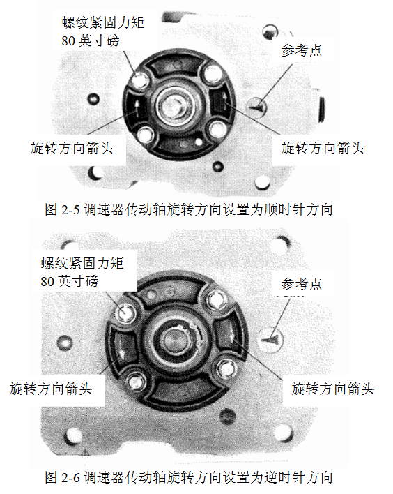
Drive shaft rotation direction
Looking down from the top of the governor, define the direction of rotation of the drive shaft, and mark the nameplate with "CW" (clockwise) or "CCW" (counterclockwise).
The transmission shaft has only one rotation direction, and the rotation direction viewed from the top should be the same as the rotation direction of the engine transmission shaft viewed from the mounting seat downwards. Otherwise, the oil pump cannot establish oil pressure, resulting in component heating and rotating component jamming.
Change the rotation direction of the transmission shaft
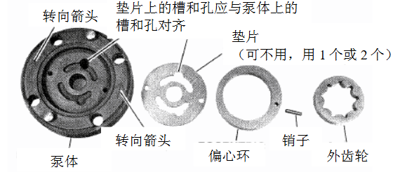
Governor with eccentric gear pump not on the lower body: Remove the governor and drain the oil, place it flat with the cooling joint facing up, rotate the transmission shaft so that the keyway is facing up, loosen the 4 pump body bolts, remove the pump body, rotate the eccentric ring so that the pin hole is close to the desired direction arrow, insert the pin, install the inner and outer gears, install the pump body on the transmission shaft and tighten it, confirm that the transmission shaft rotates flexibly, install the sleeve stop ring and leave the gap.
Gear pump eccentric speed regulator on the lower body: Remove the 4 bolts of the pump body, rotate the pump body 180 °, align the pump body arrow with the reference point of the housing. If it is screw speed regulation, screw in the speed screw clockwise. If it is lever speed regulation, turn the speed setting shaft to the maximum fuel position and hold it. Install the bolts and confirm that the transmission shaft rotates flexibly. Remove the upper cover to confirm that the sleeve rotates with the transmission shaft.
Governor installation
It can be installed horizontally or vertically. The oil cap and drain plug are installed in the factory in the vertical running position. If installed horizontally, they need to be moved to the corresponding position to ensure that the power piston is completely immersed in oil, and the oil level indicator also needs to be moved to the correct position.
- OMRON
- ABB
- General Electric
- EMERSON
- Honeywell
- HIMA
- ALSTOM
- Rolls-Royce
- MOTOROLA
- Rockwell
- Siemens
- Woodward
- YOKOGAWA
- FOXBORO
- KOLLMORGEN
- MOOG
- KB
- YAMAHA
- BENDER
- TEKTRONIX
- Westinghouse
- AMAT
- AB
- XYCOM
- Yaskawa
- B&R
- Schneider
- KONGSBERG
- NI
- WATLOW
- ProSoft
- SEW
- ADVANCED
- Reliance
- TRICONEX
- METSO
- MAN
- Advantest
- STUDER
- DANAHER MOTION
- Bently
- Galil
- EATON
- MOLEX
- DEIF
- B&W
- ZYGO
- Aerotech
- DANFOSS
- Beijer
- Moxa
- Rexroth
- Johnson
- WAGO
- TOSHIBA
- BMCM
- SMC
- HITACHI
- HIRSCHMANN
- Application field
- XP POWER
- CTI
- TRICON
- STOBER
- Thinklogical
- Horner Automation
- Meggitt
- Fanuc
- Baldor
- SHINKAWA
- Other Brands
- UniOP
- KUKA
- Iba
- Beckhoff
-
 Basler D90 96801 100 PCB Card
 -
 Basler XR2002F Voltage Regulator (110 VAC, 48-480 Hz)
 -
 Basler SR8A-2B14B3A Regulator
 -
 Basler 9561500100 Module
 -
 Basler DECS-400 BE1-11 System
 -
 Basler DECS-100-B15 Excitation Control
 -
 Basler SCP 210 Frequency Controller
 -
 Basler SR4A-2B15B3A Static Voltage Regulator
 -
 Basler BE1-32R Power Relay
 -
 Basler PIA2400-17GM Power Interface Adapter
 -
 Basler MVC 232 Manual Voltage Control Module
 -
 Basler SSR 32-12 Static Voltage Regulator
 -
 Basler 5MW AVR Generator Voltage Regulator
 -
 Basler VR63-4B Voltage Regulator
 -
 Basler DECS-100-A05 AVR for Engine Generator
 -
 Basler DECS-100-B15 Automatic Voltage Regulator
 -
 Basler BE1-32R Directional Power Relay
 -
 Basler BE1-87B Differential Relay
 -
 Basler UFOV 260A Protective Module
 -
 Basler 9-2614-02-100 PCB Rev M
 -
Basler DECS-100-B15 Digital AVR
-
 Basler 9284900103 PS DECS-400N
 -
 Basler D4N3H1U Intertie Protection
 -
 Basler DECS-100-B15 A15 AVR
 -
 Basler KR4F Voltage Regulator
 -
 Basler BE26434 T14 Transformer
 -
 Basler SR8A-2B15B3A Regulator
 -
 Westinghouse 774B472A12 AR Relay
 -
Basler DECS-100-B15 AVR
-
Basler XR2002F Regulator 110V
-
Basler SR125-E Static Regulator
-
 Basler SSR 125-12 Regulator
 -
 Basler MOC2599 Motor Pot
 -
 Basler BE1-DFPR Feeder Relay
 -
 Basler CBS 305 Current Boost
 -
 Basler BE1-25 AutoSync
 -
 Basler MVC 300 Voltage Control
 -
 Basler BE3-25A AutoSync
 -
 Basler KR7FF Static Regulator
 -
 Basler 90-49000-100 Regulator
 -
 Basler 880 kVA Dry Type Transformer Specs
 -
 Basler Electric BE1-25 Sync-Check Relay Specs
 -
 Basler SSR 125-12 Voltage Regulator Specs
 -
 Basler Electric BE1-851 Overcurrent Relay Review
 -
Basler Electric 149D930G02 Control Sub-Assembly
-
 Basler Electric BE1-81O/UT Frequency Relay Specs
 -
 Basler Electric BE1-51/27C Overcurrent Relay
 -
 Basler Electric 149D956G02 Industrial Component
 -
Basler Electric BE1-51A Overcurrent Relay Specs
-
 Basler Electric BE1-40Q Loss of Excitation Relay
 -
 Basler DECS-200 Excitation Control System
 -
 Basler DECS-200 Voltage Regulator 56-277V AC / 125V DC
 -
Basler BE1-87T Transformer Differential Relay
-
 Basler RDP-110-S1 Protection Relay
 -
 Basler BE1-700V Digital Protective Relay
 -
 Basler BE1-951 Overcurrent Protection System
 -
 Basler DECS-300 Digital Excitation Control
 -
 Basler DECS-200 Digital Excitation Control
 -
 Basler DECS-200-1C Excitation Control System
 -
Basler DECS-200-1L Digital Excitation Control
-
 Basler Electric BE1-GPS Generator Protection System
 -
Basler Electric DECS-200-1C Digital Excitation Controller
-
 Basler Electric DECS125-15 Excitation Control with Power Module
 -
 Basler Electric BE1-87G Differential Relay
 -
 Basler Electric BE1-11 Protection System I5A3M2P2N0EA00
 -
Basler Electric DECS-200-1C Excitation Control System
-
Basler Electric BE1-11g Generator Protection Relay
-
Basler Electric DECS 125-15-B2C1 V2.0.9 Excitation Control
-
 Basler Electric BE1-81O/UT3ED1JA7N2F Frequency Relay
 -
Basler Electric BE1-81O/UT3EE1YB7N1F Frequency Relay
-
 Basler Electric DECS-200-1L Digital Excitation Control System
 -
Basler DECS125-15-B2C1 Excitation Control
-
 Basler 9507900205 SSR Retrofit Voltage Regulator
 -
 Basler BE2000E Digital Voltage Regulator
 -
 Basler BE1-GPS Generator Protection System
 -
Basler DECS-250-CN1CN1N Digital Excitation Control
-
 Basler DGC-2020 Genset Controller
 -
 Basler BE1-81O UT3ED1LA7N0F Frequency Relay (Variant)
 -
 Basler BE1-81O UT3EE1YA9S0F Frequency Relay (Variant)
 -
Basler BE1-81O Over/Under Frequency Relay
-
Basler DECS125-15 Digital Excitation Control
-
Basler Electric BE1-951 Overcurrent Protection System
-
 Basler Electric BE1-700V Digital Protective Relay
 -
 Basler Electric APR63-5 Automatic Voltage Regulator
 -
Basler Electric BE1-851 Overcurrent Protection System
-
Basler Electric DECS-250-LN1SN1N Excitation Control
-
 Basler Electric BE1-87T Transformer Differential Relay
 -
Basler Electric DECS-200-1L Excitation Control System
-
 Basler Electric 9310300100 DECS-300 Excitation Control
 -
 Basler Electric SSE-N 125-4.5KW Shunt Exciter Regulator
 -
 Basler Electric DGC-2020HD-5NS1DNSBA Genset Controller
 -
Basler Electric BE1-81-O/UT3EE1JB7N1F Frequency Relay
-
Basler Electric BE1-81T1EE1WA0N1F Frequency Relay
-
 Basler Electric BE1-25M1EA6PN5R1F Sync-Check Relay
 -
 Basler Electric BE1-GPS Generator Protection System
 -
Basler Electric DECS-250-LN1SN1N Excitation Control Rev V
-
 Basler Electric DECS-250-CN2CN1N Excitation Control
 -
Basler Electric BE1-50/51B-207 Overcurrent Relay
-
Basler Electric DECS-300-C0N0 Excitation Control System
-
Basler Electric DECS-200 Digital Excitation Control System
-
Basler Electric DECS-250-LN1CN1N Excitation Unit
-
Basler Electric DECS-250 LN2SA1D Excitation Unit Specs
-
Basler Electric BE1-87T Transformer Relay Review
-
Basler Electric BE1-11 Protection System
-
Basler Electric BE1-GPS100-E4N1H1N Protection System
-
 Allen-Bradley 442G-MABH-R Safety Module
 -
 Beckhoff CX1030-0111 PLC Assembly Profile
 -
 FANUC IC693CPU364 PLC Module
 -
 Orange Denmark Type 200816 220 PLC Specs
 -
 OMRON C200H-SNT31 Sysmac PLC Module
 -
 Allen Bradley 20AB022A3AYNANC0 PowerFlex 70
 -
 OMRON C200HW-PCU01 Position Control Unit
 -
 ABB AO845A-eA Analog Output Module
 -
 OMRON CJ1M-CPU22 CPU Unit
 -
 Allen Bradley 100-E265ED11 Contactor
 -
 Honeywell 51304511-100 Interface Module
 -
 SOLEXY BXF3S0101N0018 Gateway Module
 -
 OMRON CJ2H-CPU65 CPU Unit
 -
 Automation Direct GS2-45P0 AC Drive
 -
 M68-2000 2-Axis Motion CNC Controller
 -
 OMRON CJ1M-CPU11 V3.0 PLC CPU Unit
 -
 OMRON CJ1W-NC413 4-Axis Positioning Controller
 -
 OMRON 3G2A3-PRO16 Programming Console HMI
 -
 Siemens 3VT8440-2AA04-2GA2 Molded Case Circuit Breaker
 -
 Siemens 3RT5045 Contactor Series
 -
 OMRON C200HS-CPU01-E SYSMAC PLC Controller
 -
 OMRON C500-NC103-E Positioning Control Unit
 -
 OMRON CJ1W-TC001 Temperature Control Unit


