Woodward 723 Generator Controller
Woodward 723 Generator Controller
Application and Overview
The Woodward 723 generator controller is suitable for various generator application scenarios, including auxiliary generators and diesel electric propulsion in ship systems, as well as islanding mode operation and basic load operation on infinite power grids in power plant systems. It has closed-loop speed control function, equipped with torsion filter and notch (band stop) filter, which can alleviate low-frequency oscillation problems caused by engine, generator inertia and flexible coupling. The controller has three operating modes, namely droop control based on 4-20mA megawatt sensor input or actuator position, synchronous load distribution with soft loading/unloading and automatic generator circuit breaker opening command after engine unloading, and megawatt control with soft loading/unloading and automatic generator circuit breaker opening command after engine unloading.

Hardware specifications
Model and output: The models include 8280-500, 8280-501, 8280-502, and 8280-503, which correspond to different voltages and output types. For example, 8280-500 is a high-voltage control with an actuator output of 0-200mA.
Power supply and power consumption: The power supply has 18-40Vdc (nominal 24 or 32Vdc) and 90-150Vdc (nominal 125Vdc), with a nominal power consumption of 40W.
input/output
Speed signal input: The frequency range of the magneto electric sensor is 400-15000Hz, and the proximity switch is 7.5-1000Hz.
Digital input: 8, 8mA at 24Vdc.
Analog inputs: 4, 4-20mA or 1-5VDC.
Analog output: 3, of which 2 are 4-20mA or 0-1mA (connected to instruments or computers), and 1 is 20-160mA or 4-20mA.
Output of actuator: 1, 20-160mA or 4-20mA.
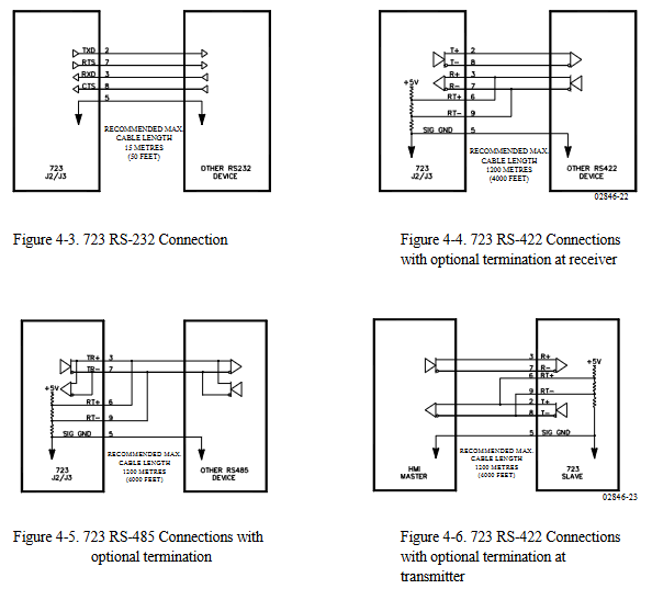
Communication port: The communication port (J1) of the programmer is RS-422, 9-pin D-type connector, 1200 baud rate, full duplex; The communication ports (J2 and J3) are RS-232, RS-422 or RS-485, 9-pin D-type connector, 1200-38400 baud rate, full duplex.
Environmental parameters: working environment temperature -40 to+70 ° C (-40 to+158 ° F), storage temperature -55 to+105 ° C (-67 to+221 ° F), humidity at 38 ° C is 95%, anti electromagnetic interference/radio frequency interference complies with MIL-STD 461C (Parts 5 and 9) in the United States, humidity complies with MIL-STD 810D Method 507.2 Procedure III in the United States, mechanical vibration is a swept sine wave of 24-2000 Hz, constant acceleration of 2.5 Gs, resonance retention -1 million cycles, total time per axis is 3/4-6 hours, mechanical impact complies with MIL-STD 810C Method 526.2 Procedure I (basic design testing), Procedure II (transport drop testing, packaging) in the United States. Program V (Workbench Operation), salt spray complies with ASTM B 117-73.

Key points of installation
Unpacking and Inspection: Before installation, it is necessary to read the relevant content on electrostatic discharge protection. When unpacking, handle the electronic controller carefully and check for any damage. If there is any damage, immediately notify the shipper.
Power requirements: The high-voltage version requires a 90-150Vdc voltage source, and the low-voltage version requires an 18-40Vdc voltage source. Both have a maximum power consumption of 40W and should not exceed the input voltage range. If battery power is used, an AC generator or other battery charging equipment should be equipped.
Location selection: The installation location should consider ventilation, maintenance space, moisture resistance, distance from electromagnetic interference sources, and avoidance of vibration. The working temperature range is -40 to+70 ° C (-40 to+158 ° F), and it cannot be installed on the engine.
Electrical connection: All shielded cables must be twisted pair, and do not attempt to tin plated braided shielding layers. All signal lines should be shielded, and the shielding layer should be connected to the nearest chassis ground. The exposed length of wires outside the shielding layer should be as short as possible, not exceeding 50mm (2 inches). The other end of the shielding layer must be open and insulated from any other conductor. Do not lay the shielded signal line together with other wires carrying high currents.
System function
Engine speed related functions
Speed sensing: The controller has two speed sensing inputs, which can be configured as torsional filtering (to make operation smoother, suitable for flexible couplings) or high signal selection (to achieve speed sensing redundancy, enabled when one signal fails). If a torsion filter is used, the speed sensors should be located on both sides of the coupling; If high signal selection is used, the two speed sensing devices should be located on the same speed measuring disc. Speed sensor # 2 can also be configured to detect the speed of the turbocharger.
Speed filtering: Each speed sensor input has a low-pass filter that can filter out unwanted frequencies on the speed sensor. If tuned above 15.9Hz, the filter will be automatically disabled. In addition, a notch filter can be enabled, and its filtering frequency should be set to the resonance frequency of the velocity signal that needs to be filtered. The filtering Q factor can adjust the attenuation degree of the signal frequency filtered by the band stop filter.
- ABB
- General Electric
- EMERSON
- Honeywell
- HIMA
- ALSTOM
- Rolls-Royce
- MOTOROLA
- Rockwell
- Siemens
- Woodward
- YOKOGAWA
- FOXBORO
- KOLLMORGEN
- MOOG
- KB
- YAMAHA
- BENDER
- TEKTRONIX
- Westinghouse
- AMAT
- AB
- XYCOM
- Yaskawa
- B&R
- Schneider
- Kongsberg
- NI
- WATLOW
- ProSoft
- SEW
- ADVANCED
- Reliance
- TRICONEX
- METSO
- MAN
- Advantest
- STUDER
- KONGSBERG
- DANAHER MOTION
- Bently
- Galil
- EATON
- MOLEX
- DEIF
- B&W
- ZYGO
- Aerotech
- DANFOSS
- Beijer
- Moxa
- Rexroth
- Johnson
- WAGO
- TOSHIBA
- BMCM
- SMC
- HITACHI
- HIRSCHMANN
- Application field
- XP POWER
- CTI
- TRICON
- STOBER
- Thinklogical
- Horner Automation
- Meggitt
- Fanuc
- Baldor
- SHINKAWA
- Other Brands


