
Woodward 723PLUS Digital Controller
Woodward 723PLUS Digital Controller
Describe
This manual introduces the hardware related content of the Woodward 723PLUS digital controller (models 9906-619, 9906-620, 9906-700), including general information, installation, control setpoint input, use of Servlink and Watch Window, product support and service options, etc. The controller is suitable for various application scenarios that require speed control.
General information
Application scenarios: It can adapt to various applications through programming. The hardware includes two speed inputs, supports two magneto electric sensors (MPUs) or proximity switches (such as for torsional filtering), as well as four analog inputs, three analog outputs, eight discrete inputs, and three discrete outputs, which can be used in load sharing systems. Its two LON channels can support related control functions.
Control options: Different models have different power input voltage requirements, and discrete input voltage provides switch command signals for control. There are also various other control options, such as proximity switch input suitable for low-frequency speed signals, 0-1mA output of instrument drivers, etc. The controller can be used in conjunction with proximity switches or magneto electric sensors with minimum frequency requirements.
Attachments: including handheld programmer (9907-205), SPM-A synchronizer, power output sensor, active power sensor, etc.
install
Scope: This includes general installation instructions for the 723PLUS controller, including power requirements, environmental precautions, location considerations, as well as unboxing, electrical connections, and installation inspection procedures.
Unpacking: Before handling the controller, it is necessary to read the relevant content on electrostatic discharge protection. When unpacking, be careful and check whether the controller is damaged. If there is any damage, immediately notify the shipper.
Power requirements: High voltage models require a 90-150Vdc voltage source, while low voltage models require an 18-40Vdc voltage source. To prevent damage to the controller, the input voltage range must not be exceeded. If battery power is used, an AC generator or other battery charging equipment must be equipped.
Location considerations: When selecting the installation location, factors such as ventilation, maintenance space, liquid and condensation prevention, electromagnetic interference prevention, and vibration prevention should be taken into account. The controller should not be installed on the prime mover, and the operating temperature range is -40 to+70 ° C (-40 to+158 ° F).
Specific installation requirements for marine use: The certification requirements for marine use types may change over time. In order to meet these requirements, all wiring, except for the part near the control connection terminal, must be inside metal conduits, and the control must be installed on a grounded metal mounting plate. It is also possible to meet attenuation requirements at specific installation locations or methods without additional special measures, but consultation with the shipyard is required.
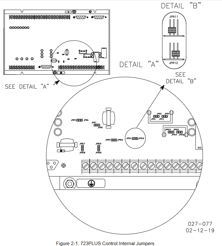
Internal jumpers: The 723PLUS controller has ten two position internal jumpers located at the top of the printed circuit board. If you need to change the jumpers, you need to read the electrostatic discharge protection content first, power off and wait before operating. Different jumpers have different default settings and functions.
Electrical connection: External wiring connection and shielding requirements should refer to relevant software manuals. All shielded cables must be twisted pair, signal lines should be shielded, and shielding layer connections should follow specific requirements. It also provides detailed instructions on the connection methods and precautions for power supply, analog output, actuator output, speed signal input, load sharing line input, discrete input, analog input, etc.
Installation inspection program: After installation, visual inspection (checking linkage devices, wiring, terminals, speed sensors, etc.) and grounding inspection are required to ensure that the resistance between each terminal of the controller and the chassis meets the requirements.
Serial port communication: The 723PLUS has two serial ports for communication, which can be configured into multiple types through software. When writing applications, it can be configured as a Modbus communication port and supports relevant protocols.
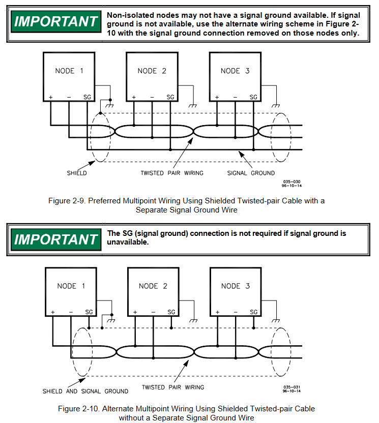
Terminal matching and grounding shielding: Different communication types (RS-422, RS-485) have different terminal matching requirements. RS-422 and RS-485 specifications require grounding wires when there are no other grounding paths between units. There are preferred and alternative wiring methods, and shielding and grounding must be handled correctly.
Control set point input
Overview: Due to differences in installation, system, and component tolerances, the 723PLUS controller must be adjusted for each system to achieve optimal performance. Setpoint inputs can be made through a handheld programmer or PC (using Watch Window software tools and Servlink software).
Handheld programmer and menu: The handheld programmer obtains power from the 723PLUS controller, connects to the RS-422 communication serial port of the controller, performs self check after power on, and displays application related information on the screen. The controller has a service menu and a configuration menu. The configuration menu needs to be entered when I/O is turned off (engine stopped), and the service menu can be directly entered through buttons. The operation menu and settings
Control set point input
Overview
Due to differences in installation environment, system, and component tolerances, the 723PLUS controller needs to be adjusted for specific systems to achieve optimal performance. Setpoint input can be completed through a handheld programmer or by connecting to a PC (using Watch Window software and Servlink software).
Handheld programmer and menu
Programmer connection and self-test
The handheld programmer (model 9907-205) obtains power from the 723PLUS controller and connects to the RS-422 communication serial port (J1 terminal) of the controller. When connecting, slightly loosen the right screw of the J1 port cover plate, rotate the cover plate clockwise to expose the 9-pin connector, and then firmly insert the programmer connector into J1.
After connecting the programmer to the controller, it will perform a power on self-test. After the self-test is completed, the screen will display two pieces of information related to the application. Press the ID key to switch between displaying the software's part number and version letter.
Menu type and access
Configure menu: It needs to be accessed while the engine is stopped. Press the corresponding button, and the screen will display "To select configure, press enter". After pressing the ENTER key, it will display "To shutdown I/O, press enter". Press the ENTER key again to enter. If the engine is running during this process, it will shut down due to controller I/O shutdown.
Service menu: Press the DOWN ARROW key to access without shutting down the engine.
Menu Operation
Move between menus: Use the LEFT ARROW and RIGHT ARROW keys.
To move between set points within the menu: use the UP ARROW and DOWN ARROW keys.
Return to menu title: Press ESC key.
Exit menu: Press the ESC key, and the configuration menu will automatically save the set points when exiting.
Setpoint adjustment
Arrange mode
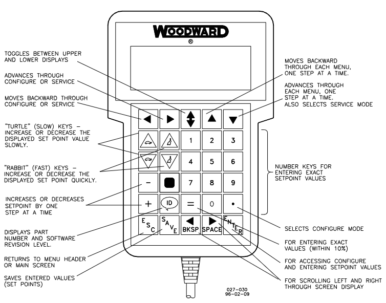
Use the TURTLE UP or RABBIT UP keys to increase the set value, and the TURTLE DOWN or RABBIT DOWN keys to decrease the set value. The adjustment rate of the RABBIT key is about 10 times that of the TURTLE key, which is suitable for situations where a large adjustment value is required.
For settings that require the selection of TRUE or False, use the corresponding increase or decrease keys.
Use the+or - keys to gradually change integer values in the application software.
To enter a precise value, press the=key, enter the desired value, and then press the ENTER key, but the value must be within 10% of the existing value.
Save Setpoints
At any time, the SAVE key can be used to save the set points and transfer the new set point values to the EEPROM memory, which retains all set points even when the controller is powered off.
To prevent the loss of set values after the controller is powered off due to the failure to save the set points, which may damage the engine, it is necessary to save the set points before removing the controller power supply.

- OMRON
- ABB
- General Electric
- EMERSON
- Honeywell
- HIMA
- ALSTOM
- Rolls-Royce
- MOTOROLA
- Rockwell
- Siemens
- Woodward
- YOKOGAWA
- FOXBORO
- KOLLMORGEN
- MOOG
- KB
- YAMAHA
- BENDER
- TEKTRONIX
- Westinghouse
- AMAT
- AB
- XYCOM
- Yaskawa
- B&R
- Schneider
- KONGSBERG
- NI
- WATLOW
- ProSoft
- SEW
- ADVANCED
- Reliance
- TRICONEX
- METSO
- MAN
- Advantest
- STUDER
- DANAHER MOTION
- Bently
- Galil
- EATON
- MOLEX
- DEIF
- B&W
- ZYGO
- Aerotech
- DANFOSS
- Beijer
- Moxa
- Rexroth
- Johnson
- WAGO
- TOSHIBA
- BMCM
- SMC
- HITACHI
- HIRSCHMANN
- Application field
- XP POWER
- CTI
- TRICON
- STOBER
- Thinklogical
- Horner Automation
- Meggitt
- Fanuc
- Baldor
- SHINKAWA
- Other Brands
- UniOP
- KUKA
- Iba
- Beckhoff
-
 Basler Electric DECS-200-1L Digital Excitation Control System
 -
 Basler DECS125-15-B2C1 Excitation Control
 -
 Basler 9507900205 SSR Retrofit Voltage Regulator
 -
 Basler BE2000E Digital Voltage Regulator
 -
 Basler BE1-GPS Generator Protection System
 -
 Basler DECS-250-CN1CN1N Digital Excitation Control
 -
 Basler DGC-2020 Genset Controller
 -
 Basler BE1-81O UT3ED1LA7N0F Frequency Relay (Variant)
 -
 Basler BE1-81O UT3EE1YA9S0F Frequency Relay (Variant)
 -
 Basler BE1-81O Over/Under Frequency Relay
 -
 Basler DECS125-15 Digital Excitation Control
 -
 Basler Electric BE1-951 Overcurrent Protection System
 -
 Basler Electric BE1-700V Digital Protective Relay
 -
 Basler Electric APR63-5 Automatic Voltage Regulator
 -
 Basler Electric BE1-851 Overcurrent Protection System
 -
 Basler Electric DECS-250-LN1SN1N Excitation Control
 -
 Basler Electric BE1-87T Transformer Differential Relay
 -
 Basler Electric DECS-200-1L Excitation Control System
 -
 Basler Electric 9310300100 DECS-300 Excitation Control
 -
 Basler Electric SSE-N 125-4.5KW Shunt Exciter Regulator
 -
 Basler Electric DGC-2020HD-5NS1DNSBA Genset Controller
 -
Basler Electric BE1-81-O/UT3EE1JB7N1F Frequency Relay
-
 Basler Electric BE1-81T1EE1WA0N1F Frequency Relay
 -
 Basler Electric BE1-25M1EA6PN5R1F Sync-Check Relay
 -
 Basler Electric BE1-GPS Generator Protection System
 -
Basler Electric DECS-250-LN1SN1N Excitation Control Rev V
-
 Basler Electric DECS-250-CN2CN1N Excitation Control
 -
 Basler Electric BE1-50/51B-207 Overcurrent Relay
 -
Basler Electric DECS-300-C0N0 Excitation Control System
-
Basler Electric DECS-200 Digital Excitation Control System
-
Basler Electric DECS-250-LN1CN1N Excitation Unit
-
Basler Electric DECS-250 LN2SA1D Excitation Unit Specs
-
Basler Electric BE1-87T Transformer Relay Review
-
Basler Electric BE1-11 Protection System
-
Basler Electric BE1-GPS100-E4N1H1N Protection System
-
 Allen-Bradley 442G-MABH-R Safety Module
 -
 Beckhoff CX1030-0111 PLC Assembly Profile
 -
 FANUC IC693CPU364 PLC Module
 -
 Orange Denmark Type 200816 220 PLC Specs
 -
 OMRON C200H-SNT31 Sysmac PLC Module
 -
 Allen Bradley 20AB022A3AYNANC0 PowerFlex 70
 -
 OMRON C200HW-PCU01 Position Control Unit
 -
 ABB AO845A-eA Analog Output Module
 -
 OMRON CJ1M-CPU22 CPU Unit
 -
 Allen Bradley 100-E265ED11 Contactor
 -
 Honeywell 51304511-100 Interface Module
 -
 SOLEXY BXF3S0101N0018 Gateway Module
 -
 OMRON CJ2H-CPU65 CPU Unit
 -
 Automation Direct GS2-45P0 AC Drive
 -
 M68-2000 2-Axis Motion CNC Controller
 -
 OMRON CJ1M-CPU11 V3.0 PLC CPU Unit
 -
 OMRON CJ1W-NC413 4-Axis Positioning Controller
 -
 OMRON 3G2A3-PRO16 Programming Console HMI
 -
 Siemens 3VT8440-2AA04-2GA2 Molded Case Circuit Breaker
 -
 Siemens 3RT5045 Contactor Series
 -
 OMRON C200HS-CPU01-E SYSMAC PLC Controller
 -
 OMRON C500-NC103-E Positioning Control Unit
 -
 OMRON CJ1W-TC001 Temperature Control Unit
 -
 OMRON NJ301-1100 NJ-PA3001 PLC System EtherCAT
 -
 Pilz 773100 M1P Safety Relay Base Unit
 -
 Siemens SINUMERIK 840D SL NCU 720.3B with PLC 317-3 PN/DP
 -
 Siemens 6AV6618-7GD01-3AB0 HMI Panel
 -
 OMRON F150-C15E-3 Vision Mate Controller PLC Overview
 -
 Mitsubishi MELSEC A Series PLC System A63P A3ACPU A616AD A68RD3
 -
 M68-2000 2 Axis Motion Controller SCE SERVO CNC
 -
 OMRON FZ-S2M PLC Camera Vision System
 -
 VISOLUX SLVA-4K PLC Module from Elektronik GmbH
 -
 OMRON CJ1M-CPU23 V2.0 PLC CPU Unit
 -
 ABB AI86-16CHF PCB Card 5761751-9 B Specifications
 -
 Allen-Bradley 100-D140ZJ22L Contactor Overview
 -
 Merlin Gerin PB80 PLC Rack
 -
 WEIR WE203 Power Supply PLC
 -
 OMRON NX-TS3102 Temperature Input Unit
 -
 Siemens 6ES7146-6FF00-0AB0 I/O Module
 -
 Fanuc A16B-3300-0057 Circuit Board
 -
 OMRON CJ1W-IDP01 Input Module
 -
 Siemens 6FX2007-1AD13 Handheld Unit
 -
 Gems EM54 PLC Module PCB
 -
 Beckhoff CX2030-0121 Embedded PC CPU
 -
 OMRON NJ301-1100 Machine Automation Controller
 -
 Biesse Rover CNI PLC 2153 030 7146.30 Numerical Control Module
 -
 OMRON CJ1W DA08V Analog Output Module
 -
 OMRON CS1D ETN21D Ethernet Module
 -
 Allen Bradley 1768 L43 CompactLogix Controller
 -
 Schneider TWDLMDA40DTK Twido PLC Module
 -
 Mitsubishi NZ2EX2B 60AD4 Analog Input Module
 -
 OMRON NS8 TV00B V2 Touch Display Panel
 -
 Mitsubishi AY71 CMOS TTL Output Module
 -
 OMRON C500 CPU11 E Processor Module
 -
 OMRON CJ1W PTS51 Temperature Input Module
 -
 Siemens 6SL3100-1DE22-0AA1 600V DC Supply
 -
 OMRON CJ1M-CPU23 PLC CPU 9‑Pin Serial
 -
 Schlumberger IMT4N 24‑250VAC 48‑230VAC PLC Timer
 -
 OMRON CJ1M-CPU22 PLC CPU Unit V2.0
 -
 Allen‑Bradley 2711P-B7C6D2 Touch Screen PanelView
 -
 ADSP-2181KST-160 Analog Devices DSP IC Specs
 -
 Schneider LC1F400 400A Contactor Specifications
 -
 Yaskawa SGDH-10DE-OY 1kW 400V Servo Drive
 -
 Schneider TM262L10MESE8T M262 PLC 5ns Inst
 -
 Mitsubishi AA104VJ05 10.4in LCD Panel Specs
 -
 Allen Bradley 1761-L32BWA MicroLogix 1000 PLC
 -
 Siemens 6ES7431-7KF00-0AB0 Analog Input Module
 -
 Allen Bradley 1769-OB16 Output Module
 -
 Siemens 6ES7131-1BL12-0XB0 Input Module
 -
 Beckhoff EP7041-3002 EtherCAT Box Module
 -
 Siemens RK7243-2AA30-0XB0 Communication Module
 -
 Siemens 4AM5742-8DD40-0FA0 Transformer
 -
 Siemens 3TK2834-1BB40 Safety Relay
 -
 Brother BAS 311 Sewing Machine Circuit Board
 -
Yaskawa SGDH-10DE-OY Servo Driver
-
 OMRON C60H C6DR DE V1 Sysmac PLC
 -
 MITSUBISHI ELECTRIC A2ACPU21 S1 CPU Module
 -
 ABB BAILEY INNPM12 Network Process Module
 -
 HONEYWELL 620 0073C IPC PLC Module
 -
 Mitsubishi 15050 PR02B PLC Circuit Board
 -
 SIEMENS 6SY7000 0AC37 Drive Control Module
 -
 OMRON TJ2 ECT16 Traxial EtherCAT Controller
 -
 GE Fanuc IC698PSD300D Power Supply Module
 -
 Texas Instruments Series 505 16 Position Base
 -
 OMRON YASKAWA SGDH 10DE OY Servo Drive
 -
 Allen‑Bradley 440G-MT Safety Interlock Switch Specs
 -
 Rubycon PD27A 24V 8A Power Supply Module
 -
 SK-H1-GDB1-F11D PLC Gate Driver Board Kit
 -
 VIPA 441-4UA14 451-4UA14 PLC Module Rack
 -
 Mitsubishi FX5U-80MT ESS PLC Controller Specs
 -
 Mitsubishi Q64TCRTN Temperature PLC Module
 -
 GE 1C31170G Rev10 PLC Circuit Board Module
 -
 Schneider TWDLMDA40DTK PLC Controller Module


