
How to install Johnson AE55/NIE55?
How to install Johnson AE55/NIE55?
Equipment Overview and Application Scenarios
core positioning
NAE (Network Automation Engine) and NIE (Network Integration Engine) are monitoring devices that support web access and are based on Ethernet. Their core functions are to monitor and control on-site building automation equipment, HVAC equipment, and lighting systems. Unless otherwise specified in the document, the MS-NAE55xx-x and MS-NIE55xx-x series are collectively referred to as NAE55.
Emission compliance requirements
United States: Compliant with FCC Part 15 Class A digital device restrictions, only applicable to commercial environments. If interference occurs in residential environments, users need to resolve it themselves.
Canada: Meets the requirements of the Canadian Interference Equipment Regulations (R è glement sur le mat é riel brouilleur du Canada).
Preparation before installation
Package contains components
1 NAE55 host
1 data protection battery (individually packaged)
1 installation manual
Required materials and specialized tools
4 fasteners for compatible mounting surfaces (M4 screws for Europe, # 8 screws for North America)
2 sections of DIN rails 36 centimeters (14 inches) and above (only for DIN rail installation scenarios)
1 small flathead screwdriver (used to fix the communication cable of the terminal block)
Installation environment requirements
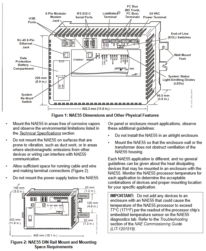
Stay away from corrosive gases and follow the environmental restrictions specified in the technical specifications.
Avoid installing on surfaces that are prone to vibration (such as pipelines) or near electromagnetic interference sources (to prevent interference with communication).
Reserve sufficient space for wiring and terminal connections (refer to size requirements in Figure 2).
The power supply should not be installed below NAE55.
When installing panels/enclosures, it is necessary to avoid sealing the enclosure and ensure that the enclosure walls or transformers do not obstruct the equipment ventilation openings.
Devices that cause the temperature of the NAE55 processor to exceed 77 ° C (171 ° F) must not be added inside the casing (embedded temperature sensor data must be viewed through diagnostic tags).
Installation process
Installation method selection
NAE55 supports three installation methods: wall mounting, DIN rail mounting, and shell mounting. The core operations are as follows:
1. Wall installation (vertical surface)
Mark the four installation hole positions on the wall according to the dimensions in Figure 3 (horizontal installation hole spacing of 317.5mm, vertical installation hole spacing of 63.5mm) or directly using the host as a template.
After drilling, if anchor bolts need to be fixed, they should be inserted into the holes. First, screw the screws into the top two holes, leaving enough space to accommodate the installation feet.
When installing horizontally, hang the top mounting foot of the host on the screw; When installing vertically, the host needs to be held in a fixed position.
Insert the screws into the two holes at the bottom, being careful not to tighten them too tightly (to avoid damaging the mounting feet or housing).
2. DIN rail installation
Install two sections of DIN rails horizontally, with a center to center distance of 125 millimeters (4.9 inches).
Pull the DIN buckle at the bottom of the host to the outer position.
Hang the DIN rail hook on the back of the host onto the rail.
Push the DIN buckle back to its original position and secure the host.
Disassembly steps: First, move the DIN buckle to the outside, and then remove the host from the guide rail.
3. Shell installation
Install the casing according to the manufacturer's instructions.
Following the "Installation Environment Requirements" and the above installation specifications, fix NAE55 inside the casing.
Special installation requirements
The UL 864 certified models (MS-NAE5510-0U and MS-NIE5510-0U) must be installed inside a lockable housing.
Wiring operation
Precautions before wiring
Before wiring, a data protection battery must be installed (see "Settings and Adjustments" section), and a 24VAC power supply must not be connected.
Only copper conductors are used, and wiring must comply with local, national, and regional regulations.
Do not exceed the electrical rating of the equipment (NAE55 is a low-voltage equipment,<30VAC), and do not connect to high voltage (otherwise the equipment will be damaged and the warranty will be invalidated).
The terminal block key must not be removed, and the terminal plug and socket are designed to be foolproof and can only be correctly connected.
Prevent electrostatic discharge (avoid damaging equipment and void warranty).
The power cord and communication cable should be kept at least 50 millimeters (2 inches) away from the ventilation duct on the side of the equipment.
Reserve a certain degree of slack in the cables, and arrange the wiring neatly to ensure ventilation, LED visibility, and maintenance convenience.
Core wiring steps
Ethernet connection: Insert the Ethernet cable into an 8-pin RJ-45 Ethernet port (supporting 10/100 Mbps).
Building Automation System (BAS) Network Connection:
- OMRON
- ABB
- General Electric
- EMERSON
- Honeywell
- HIMA
- ALSTOM
- Rolls-Royce
- MOTOROLA
- Rockwell
- Siemens
- Woodward
- YOKOGAWA
- FOXBORO
- KOLLMORGEN
- MOOG
- KB
- YAMAHA
- BENDER
- TEKTRONIX
- Westinghouse
- AMAT
- AB
- XYCOM
- Yaskawa
- B&R
- Schneider
- KONGSBERG
- NI
- WATLOW
- ProSoft
- SEW
- ADVANCED
- Reliance
- TRICONEX
- METSO
- MAN
- Advantest
- STUDER
- DANAHER MOTION
- Bently
- Galil
- EATON
- MOLEX
- DEIF
- B&W
- ZYGO
- Aerotech
- DANFOSS
- Beijer
- Moxa
- Rexroth
- Johnson
- WAGO
- TOSHIBA
- BMCM
- SMC
- HITACHI
- HIRSCHMANN
- Application field
- XP POWER
- CTI
- TRICON
- STOBER
- Thinklogical
- Horner Automation
- Meggitt
- Fanuc
- Baldor
- SHINKAWA
- Other Brands
- UniOP
- KUKA
- Iba
- Beckhoff
- ADLINK
-
 SIGMATEK 0332.554.03 Board 371071000154
 -
 SIGMATEK 12-250-021 Base Plate Back Panel CM5V020
 -
 SIGMATEK DM162 S-DIAS Digital Mix Module
 -
 DEMAG ERGOTECH 061 381 66 Sigmatek 9842.243.02 Circuit Board
 -
 SIGMATEK CP313-1 PLC Module
 -
 Sigmatek ETV0551-2 VARAN Touch Terminal
 -
 Sigmatek SDM 081 FS S-Dias Safety Module
 -
 DEMAG 05-250-023 Ergotech Motherboard with Sigmatek TMS012
 -
Sigmatek CM5V020 12-250-023-K Wiring Base
-
 Sigma Tek 5000B-37 Attitude Gyro Indicator
 -
 Sigmatek SDD120-2 DIAS Drive
 -
 Sigmatek CME221 Memory Module
 -
 Sigmatek DCP640 DIAS Central Unit
 -
 Sigmatek STO040 Safety Output Module
 -
 Sigmatek CET281 Control Panel
 -
 Sigmatek CIPC LX800 Demag NC5 CPU
 -
 Sigmatek DKL093 05-024-093 Terminal Module
 -
 Sigmatek AI088 20-009-088 Analog Input Module
 -
 Sigmatek CAI888 Analog Input Module
 -
 SIGMATEK CCA021 12-025-021 Analog Output Module
 -
SIGMATEK 1104.579.05 Control Module
-
SIGMATEK SDI100 Digital Input Module
-
 SIGMATEK C-IPC 256MB LX800 Compact Dias
 -
 SIGMATEK 9423.090.02 Control Module
 -
SIGMATEK C-IPC 256 Power Supply 148498
-
 SIGMATEK CAI025 Analog Input Module
 -
 SIGMATEK CTO166 Digital Output Module
 -
 SIGMATEK CP112 20-004-112 Processor Module
 -
SIGMATEK CAI887 12-009-887 Safety Module
-
 Sigma-Tek 4000B-31 Directional Gyro 1U262-002-42
 -
Sigmatek C-IPC 256MB LX800 IPC Controller
-
Sigmatek C-IPC 01-450-031 Industrial PC LX800
-
Sigmatek C-IPC 256 Industrial PC Controller
-
Sigmatek CCP-531 PLC Processor Module
-
Sigmatek CDI163 Digital Input Module
-
 Sigmatek ETV0501 VARAN Terminal 12-230-0501
 -
 Sigmatek CTMS020 C-DIAS Technology Module
 -
 Sigmatek CIV512 VARAN Switch Module
 -
 Sigmatek HU011 20-080-011 Interface Module
 -
 SIGMATEK SLIDES DAM 124 Module
 -
 SIGMATEK C-IPC 161 01-450-161L Industrial PC
 -
SIGMATEK C-IPC 128MB VIA 733MHz 01-450-024-K
-
 SIGMATEK 12-780-012 R8-IPC Geode LX800 Module
 -
SIGMATEK CAM124 Analog Module
-
 SIGMATEK S1 032-8AF61-R4 EZ Servo Motor
 -
 SIGMATEK CTO163 Digital Output Module
 -
 SIGMATEK CCP082 12-004-082 Processor Module
 -
 SIGMATEK CRCH081 C-DIAS Temperature Module
 -
 SIGMATEK PC322-K 01-310-322-K Industrial PC
 -
SIGMATEK SDD310-2 Servo Drive
-
 SIGMATEK AI084 Analog Input Module
 -
SIGMATEK CRCH081 12-752-081 Temperature Module
-
Sigma-Tek 5000L-4 Attitude Gyro 1U284-001-3
-
 SIGMATEK CM5V020 12-250-023-K Wiring Module
 -
Sigma-Tek 4000H-6 Directional Gyro IU262-035-7
-
 SIGMATEK Dias DCP160 05-004-160 Processor Module
 -
SIGMATEK 0147.395.02 Control Module
-
SIGMATEK A1084 Control Module
-
SIGMATEK DI200 20-006-2000 Digital Input Module
-
Sigmatek DNC115 Encoder Module
-
 Sigmatek DAM122 05-017-122 Analog Module
 -
Sigmatek 9802.289.01 Control Board TA71 Display
-
Sigmatek TO127 20-007-127 Digital Output Module
-
Sigmatek DNC031 05-011-031 Digital Module
-
Sigmatek VI022 20-003-022 Interface Module
-
Sigmatek CAI085 Analog Input Module
-
 Sigmatek CP111 S-DIAS CPU Module
 -
 Sigmatek CTMS030 Krauss Maffei Module
 -
 Sigmatek CAM123 Control Module
 -
 Sigmatek TAE732-P 01-240-732-P Touch Display Unit
 -
Sigmatek MDM021 Digital Mixed Module
-
Sigmatek DCP642 DIAS Central Unit
-
 Sigmatek CST022 12-014-022 C-DIAS Module
 -
 Sigmatek SRO021 20-893-021 Safety Relay Output
 -
 Krauss Maffei MC5 Control System Sigmatek
 -
 Sigmatek DC061 Module 18-24VDC 300mA
 -
 Herrmann EVT0855 Ultrasonic Welder Touch Panel
 -
Sigmatek CIV521 Control Module 1.4A 2W
-
 Sigmatek DDI61 05-006-161 Digital Input Module
 -
SIGMATEK ETT312-E Touch Terminal 01-230-312
-
Cessna S3326-1 Sigma Tek 5000B-67 Gyro 1U149-015-9
-
SIGMATEK PS101 Power Supply Module
-
SIGMATEK 0332.554.03 Control Module 371071000154
-
 SIGMATEK ETT312-E Touch Terminal 01-230-312
 -
SIGMATEK CDM163 Control Module
-
 SIGMATEK VSV046 16-023-046 Module
 -
SIGMATEK AM221 20-017-221 Analog Module
-
SIGMATEK CTS051 12-053-051 Control Module
-
SIGMATEK AM221 20-017-221 Analog Module
-
Sigmatek CSDI161 12-891-161 Safety Input Module
-
Sigma Tek 4000C-1 Directional Gyro Indicator
-
Sigmatek ETV0501 12-230-0501 VARAN Terminal
-
Sigmatek DDM165 SLIDES Module
-
 Sigmatek N100 20-011-100 Control Module
 -
Sigmatek AKM54K-ANC2R-B0 PM Servo Motor
-
Sigmatek CTO166 Digital Output Module
-
Sigmatek CP212-K 20-004-212-K CPU Module
-
Sigmatek CDI161 Digital Input Module
-
Sigmatek DCC080 05-700-080-2 Control Module
-
 SIGMATEK SCP011 S-DIAS Safety CPU
 -
SIGMATEK SCP011 S-DIAS Safety CPU
-
SIGMATEK SRO022 Relay Output Module
-
SIGMATEK MDD 121 Drive Axis Module
-
SIGMATEK DSI021 SLIDES Siemens Interface
-
SIGMATEK DIAS DCP161 Module 05-004-161
-
 Sigmatek ETT312 Built-in Touch Terminal
 -
SIGMATEK DCP 643 DIAS Controller System
-
SIGMATEK CIO021 Multi I/O Module
-
SIGMATEK CTMS020 Control Module
-
 Sigmatek CME 221 Memory Module
 -
Sigmatek 0420.615.01 Control Board
-
Sigmatek CP111 20-004-111 CPU Module
-
Sigmatek 9405.065.03 Control Board
-
Sigmatek ETEK 01-450-032-K C-IPC 256MB Industrial PC
-
Sigmatek CTO163 12-007-163 Safety Output Module
-
Sigmatek TO081 20-007-081 Digital Output Module
-
 Sigmatek SI021 20-022-021 Safety Input Module
 -
Sigmatek 05-052-014 Control Module HW 1.0
-
Sigmatek TO127 20-007-127 Digital Output Module
-
Sigmatek SV141 20-023-141 VARAN Splitter
-
 SIGMATEK CIV513 C-DIAS VARAN Control Module
 -
Sigmatek DCP 642 SLIDES Control Module with DKL002
-
Sigma-Tek 5000B-36 Attitude Gyro
-
SIGMATEK 01-450-024 C-IPC Industrial Computer
-
SIGMATEK CP102 S-DIAS Processor Module
-
Sigmatek CRCH081 12-752-081 PLC Module
-
SIGMATEK SDD340-46 Series Drive
-
SIGMATEK TAE731 Touch Display Unit


