KOLLMORGEN AKD ® Servo driver CANopen communication
DS402 driver sub protocol object
6040h (control word): 16 bit control word, bit 0 controls "on/off", bit 2 controls "quick stop", bit 3 controls "operation enable", bit 7 controls "fault reset", used to drive state machine switching.
6041h (Status Word): A 16 bit status word, with bit 0 indicating "ready to start", bit 1 indicating "on", bit 2 indicating "operation enabled", and bit 3 indicating "fault", used to provide feedback on the current status of the driver.
6060h (Operation Mode): Set the driver operation mode, supporting trajectory position mode (01h), trajectory speed mode (03h), trajectory torque mode (04h), zero calibration mode (06h), interpolation position mode (07h), etc., and switch modes when the motor is at zero speed.
607Ah (target position): a 32-bit integer, the target position setting value in trajectory position mode, supports absolute/relative position control, and the unit is defined by the gear ratio (6091h) and feed in constant (6092h).
6064h (actual position value): 32-bit integer, feedback driver actual position, resolution can be adjusted through object 608Fh (position encoder resolution).
6098h (zeroing method): an 8-bit integer, defining the zeroing method (such as -7 for negative direction zeroing input and feedback zeroing, 8 for positive direction reference switch zeroing), which needs to be used in conjunction with zeroing velocity (6099h) and zeroing acceleration (609Ah).
Manufacturer specific object
2001h (System Fault): Array type, storing the last 10 system fault numbers, Subindex 1-10 corresponds to DRV.FAULTRA1-DRV.FAULTRA10, read-only.
2011h (DRV. RUNTIME): A 32-bit unsigned integer that records drive runtime in seconds and is read-only.
20A4h (Latch Control Register): A 16 bit register that controls the monitoring enable of the latch (such as bit 0 enabling the rising edge of external latch 1) and supports position capture function.
345Ah (brake control): array type, Subindex 1 controls the brake command (0=hold brake, 1=release), Subindex 2 provides feedback on the brake status, supports direct control of the brake via fieldbus, and it should be noted that in case of a fault, the driver will take over the brake logic again.

(2) Example of Core Function Configuration
PDO configuration: Taking "controlling motor speed through PDO" as an example, it is necessary to first disable unused PDO to reduce bus load, then configure RXPDO to map target speed (60FFh), TXPDO to map actual speed (606Ch), and finally enable PDO and set synchronous triggering mode (such as transmitting PDO once every SYNC message received).
Zeroing configuration: Write the zeroing method (6098h=-7), zeroing speed (6099h Sub1=10000 counts/s), zeroing acceleration (609Ah=1000 counts/s ²) through SDO, and then trigger the zeroing operation through the control word (6040h). After zeroing is completed, set the status word (6041h) bit 12 to 1 to indicate successful zeroing.
Trajectory position control: Set the operation mode to Trajectory position mode (6060h=01h), write the target position (607Ah), trajectory velocity (6081h), and trajectory acceleration (6083h) through RXPDO, trigger control word bit 4 to start motion, and TXPDO provides real-time feedback on the actual position (6064h) and motion status.
Fault handling and emergency messages
(1) Emergency error codes and fault classification
The manual provides a detailed list of error codes corresponding to CANopen emergency messages, covering categories such as hardware failures, power failures, motor/feedback failures, communication failures, etc. Typical codes are as follows:
Error code, fault type description, remedial measures
0x3210 Power failure F501 DC bus overvoltage reduces load deceleration rate, check regeneration resistor connection
0x3220 power failure F502 DC bus undervoltage check input power stability, troubleshooting loose wiring
0x4310 Temperature Fault F235 Drive Heat Sink Overheats, Clean Heat Dissipation Channel, Check Fan Operation Status, Reduce Load
0x7380 Feedback Fault F402 Feedback 1 Analog Signal Amplitude Fault Check Feedback Cable Wiring, Replace Feedback Equipment
0x8480 Motor Fault F302 Motor Overspeed Increase Speed Threshold (VL.THRESH), Optimize Speed Loop Parameters
0xFF02 current fault F529 exceeds Iu current offset limit check current sensor, recalibrate current loop
(2) Troubleshooting process
Identify fault codes: Obtain error codes by reading the DRV.FAULTRAS command through the driver panel (dual 7-segment screen displaying "F+code", such as F501), LED indicator light (red flashing=fault), or WorkBench software.
Identify the cause of the fault: According to the "CANopen Emergency Messages and Error Codes" section of the manual, match the fault type corresponding to the code (such as power supply, feedback, temperature), and investigate the hardware wiring, parameter configuration, and environmental conditions (such as temperature and load).
Implement remedial measures:
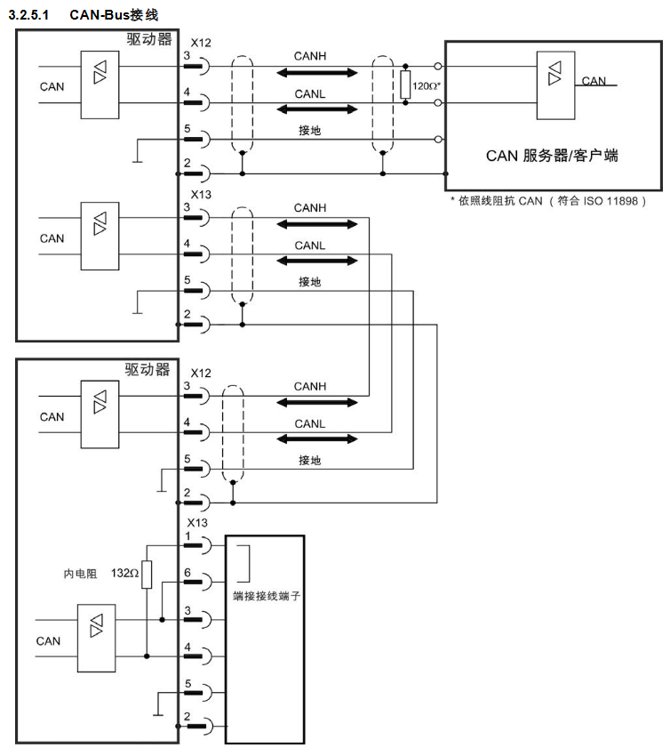
Wiring faults (such as feedback disconnection): After power failure, unplug the cable and confirm the pin correspondence (refer to the attached wiring diagram).
- ABB
- General Electric
- EMERSON
- Honeywell
- HIMA
- ALSTOM
- Rolls-Royce
- MOTOROLA
- Rockwell
- Siemens
- Woodward
- YOKOGAWA
- FOXBORO
- KOLLMORGEN
- MOOG
- KB
- YAMAHA
- BENDER
- TEKTRONIX
- Westinghouse
- AMAT
- AB
- XYCOM
- Yaskawa
- B&R
- Schneider
- Kongsberg
- NI
- WATLOW
- ProSoft
- SEW
- ADVANCED
- Reliance
- TRICONEX
- METSO
- MAN
- Advantest
- STUDER
- KONGSBERG
- DANAHER MOTION
- Bently
- Galil
- EATON
- MOLEX
- DEIF
- B&W
- ZYGO
- Aerotech
- DANFOSS
- Beijer
- Moxa
- Rexroth
- Johnson
- WAGO
- TOSHIBA
- BMCM
- SMC
- HITACHI
- HIRSCHMANN
- Application field
- XP POWER
- CTI
- TRICON
- STOBER
- Thinklogical
- Horner Automation
- Meggitt
- Fanuc
- Baldor
- SHINKAWA
- Other Brands


