
KOLLMORGEN AKD ® Servo driver CANopen communication
AKD ® Servo driver CANopen communication
CANopen Communication Fundamentals and Hardware Configuration
(1) CAN Bus hardware interface and settings
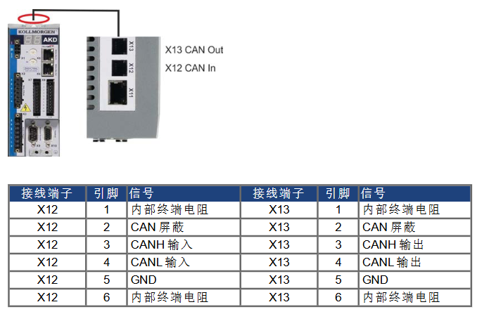
Interface definition: Two 6-pin RJ-12 terminals, X12 (CAN input) and X13 (CAN output), are used, with clear pin functions. Pin3 is CANH, Pin4 is CANL, Pin2 is shielding layer, Pin5 is GND, and Pin1 and Pin6 are used to activate the built-in 132 Ω terminal resistor (only devices at both ends of the bus need to be enabled).
Key parameter configuration
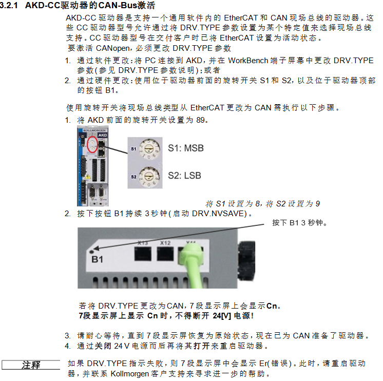
Baud rate: Supports fixed baud rates of 125/250/500/1000 kBit/s and automatic detection mode, set through parameter FBUS.PARAM01 or the driver front panel rotary switch (S1=9, S2 corresponds to 0-4). The automatic detection mode requires the driver to listen to valid CAN frames on the bus and match the bit time.
Node address: Set by the S1 (MSB) and S2 (LSB) rotary switches on the front panel of the driver, with an address range of 1-127, and associated with the IP address (such as S1=4, S2=5 corresponding to CAN address 45, IP address 192.168.0.45), which can be separated from the rotary switch configuration through WorkBench.
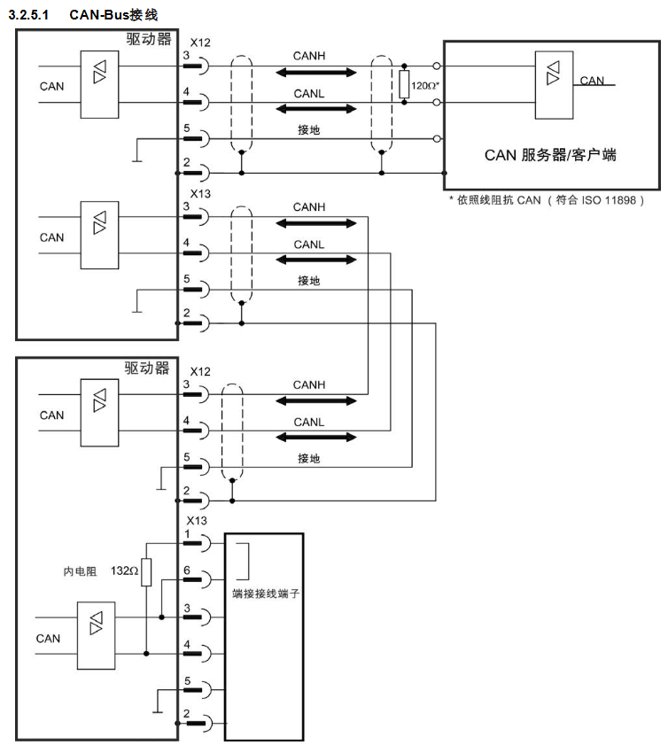
Terminal resistor: The AKD at both ends of the bus needs to activate the built-in terminal resistor, which can be short circuited to X13 terminals Pin1 and Pin6 using an optional terminal plug (P-AKD-CAN-TERM). Non terminal devices need to disconnect the terminal resistor to avoid signal reflection.
Cable requirements: Shielded twisted pair cables with characteristic impedance of 100-120 Ω must be used, and the maximum cable length varies with the baud rate (10m at 1000 kBit/s, 70m at 500 kBit/s, 115m at 250 kBit/s). The cable capacitance must be ≤ 60 nF/km, the lead loop resistance must be ≤ 159.8 Ω/km, and the shielding layer must be reliably grounded to ensure EMC performance.
(2) CANopen core communication protocol
Communication Object (COB): CANopen communication is based on an 11 bit COB-ID to identify the communication object, with priority determined by the ID. The core objects include:
Network Management Object (NMT): COB-ID=0, used for node start/stop, communication reset (such as resetting nodes with cs=129, starting nodes with cs=1).
Synchronization Object (SYNC): The default COB-ID is 0x80, providing a periodic clock for the bus and supporting multi axis synchronous motion. COB-ID can be modified through object 1005h, and the communication cycle period (in μ s) can be defined through object 1006h.
Emergency Object (EMCY): High priority event trigger object, COB-ID=0x80+node address, containing 2-byte error code, 1-byte error register, and 1-byte error category, used to report drive failures (such as overvoltage and overcurrent).
Service Data Object (SDO): Used to access object dictionaries, supports parameter reading and writing (such as downloading motor parameters and reading fault history through SDO), uses acknowledgment communication, and includes protocols such as initiating download/upload, segment transfer, and terminating transfer.
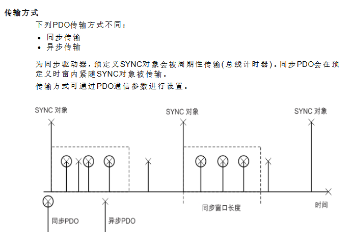
Process Data Object (PDO): used for real-time data interaction, divided into receiving PDO (RXPDO, master station → driver, such as control word, target speed) and transmitting PDO (TXPDO, driver → master station, such as status word, actual position), supporting three transmission methods: event triggered, time triggered, and synchronous triggered.
Data types: Define unsigned integers (UNSIGNED8/16/32, etc.), signed integers (INTEGER 8/16/32, etc.), mixed data types (STRUCT/ARRAY), and extended data types (OCTET_STRING/VIIBLE_STRING), with transmission using "low order first" (Intel format) to ensure multi device data compatibility.
Object Dictionary and Core Function Configuration
(1) Object Dictionary Classification and Key Objects
The object dictionary is the core of CANopen communication, which is divided into DS301 standard objects (1000h-1FFFh), manufacturer specific objects (2000h-3FFFh), and DS402 driver sub protocol objects (6000h-6FFFh) according to their functions. The key objects are as follows:
DS301 standard object
1000h (device type): Identify the device as a servo drive (DS402 sub protocol), default value 0x00020192, read-only.
1001h (Error Register): A 1-byte register, where bit 0 represents a general error, bit 1 represents a current error, bit 2 represents a voltage error, and bit 3 represents a temperature error, used to quickly locate the type of fault.
1003h (predefined error field): Array type, stores the last 10 emergency error records, Subindex 0 represents the number of errors, Subindex 1-10 stores specific error codes.
1400h-1403h (RXPDO communication parameters): Define the COB-ID (default 0x200+node address, etc.) and transmission type (such as 0xFF for event triggering) of RXPDO.
1600h-1603h (RXPDO mapping parameters): Configure RXPDO data content, default RXPDO1 mapping control word (6040h), customizable mapping target position (607Ah), target velocity (60FFh), etc.
1800h-1803h (TXPDO communication parameters): Define the COB-ID of TXPDO (default 0x180+node address, etc.), disable time (to avoid bus overload), and event timer.
1A00h-1A03h (TXPDO mapping parameters): Configure TXPDO data content, default TXPDO1 mapping status word (6041h), customizable mapping actual position (6064h), actual speed (606Ch), etc.
DS402 driver sub protocol object
6040h (control word): 16 bit control word, bit 0 controls "on/off", bit 2 controls "quick stop", bit 3 controls "operation enable", bit 7 controls "fault reset", used to drive state machine switching.
6041h (Status Word): A 16 bit status word, with bit 0 indicating "ready to start", bit 1 indicating "on", bit 2 indicating "operation enabled", and bit 3 indicating "fault", used to provide feedback on the current status of the driver.
6060h (Operation Mode): Set the driver operation mode, supporting trajectory position mode (01h), trajectory speed mode (03h), trajectory torque mode (04h), zero calibration mode (06h), interpolation position mode (07h), etc., and switch modes when the motor is at zero speed.
607Ah (target position): a 32-bit integer, the target position setting value in trajectory position mode, supports absolute/relative position control, and the unit is defined by the gear ratio (6091h) and feed in constant (6092h).
6064h (actual position value): 32-bit integer, feedback driver actual position, resolution can be adjusted through object 608Fh (position encoder resolution).
6098h (zeroing method): an 8-bit integer, defining the zeroing method (such as -7 for negative direction zeroing input and feedback zeroing, 8 for positive direction reference switch zeroing), which needs to be used in conjunction with zeroing velocity (6099h) and zeroing acceleration (609Ah).
Manufacturer specific object
2001h (System Fault): Array type, storing the last 10 system fault numbers, Subindex 1-10 corresponds to DRV.FAULTRA1-DRV.FAULTRA10, read-only.
2011h (DRV. RUNTIME): A 32-bit unsigned integer that records drive runtime in seconds and is read-only.
20A4h (Latch Control Register): A 16 bit register that controls the monitoring enable of the latch (such as bit 0 enabling the rising edge of external latch 1) and supports position capture function.
345Ah (brake control): array type, Subindex 1 controls the brake command (0=hold brake, 1=release), Subindex 2 provides feedback on the brake status, supports direct control of the brake via fieldbus, and it should be noted that in case of a fault, the driver will take over the brake logic again.
(2) Example of Core Function Configuration
PDO configuration: Taking "controlling motor speed through PDO" as an example, it is necessary to first disable unused PDO to reduce bus load, then configure RXPDO to map target speed (60FFh), TXPDO to map actual speed (606Ch), and finally enable PDO and set synchronous triggering mode (such as transmitting PDO once every SYNC message received).
Zeroing configuration: Write the zeroing method (6098h=-7), zeroing speed (6099h Sub1=10000 counts/s), zeroing acceleration (609Ah=1000 counts/s ²) through SDO, and then trigger the zeroing operation through the control word (6040h). After zeroing is completed, set the status word (6041h) bit 12 to 1 to indicate successful zeroing.
Trajectory position control: Set the operation mode to Trajectory position mode (6060h=01h), write the target position (607Ah), trajectory velocity (6081h), and trajectory acceleration (6083h) through RXPDO, trigger control word bit 4 to start motion, and TXPDO provides real-time feedback on the actual position (6064h) and motion status.
Fault handling and emergency messages
(1) Emergency error codes and fault classification
The manual provides a detailed list of error codes corresponding to CANopen emergency messages, covering categories such as hardware failures, power failures, motor/feedback failures, communication failures, etc. Typical codes are as follows:
Error code, fault type description, remedial measures
0x3210 Power failure F501 DC bus overvoltage reduces load deceleration rate, check regeneration resistor connection
0x3220 power failure F502 DC bus undervoltage check input power stability, troubleshooting loose wiring
0x4310 Temperature Fault F235 Drive Heat Sink Overheats, Clean Heat Dissipation Channel, Check Fan Operation Status, Reduce Load
0x7380 Feedback Fault F402 Feedback 1 Analog Signal Amplitude Fault Check Feedback Cable Wiring, Replace Feedback Equipment
0x8480 Motor Fault F302 Motor Overspeed Increase Speed Threshold (VL.THRESH), Optimize Speed Loop Parameters
0xFF02 current fault F529 exceeds Iu current offset limit check current sensor, recalibrate current loop
(2) Troubleshooting process
Identify fault codes: Obtain error codes by reading the DRV.FAULTRAS command through the driver panel (dual 7-segment screen displaying "F+code", such as F501), LED indicator light (red flashing=fault), or WorkBench software.
Identify the cause of the fault: According to the "CANopen Emergency Messages and Error Codes" section of the manual, match the fault type corresponding to the code (such as power supply, feedback, temperature), and investigate the hardware wiring, parameter configuration, and environmental conditions (such as temperature and load).
Implement remedial measures:
Wiring faults (such as feedback disconnection): After power failure, unplug the cable and confirm the pin correspondence (refer to the attached wiring diagram).
Parameter type faults (such as bus overvoltage): Adjust parameters through SDO (such as reducing deceleration rate), save and restart the drive.
Hardware faults (such as power level faults): If restarting is ineffective, contact technical support to return to the factory for repair.
Clear fault: Clear the fault by controlling bit 7 (fault reset) or DRV.CLRFAULTS command, confirm that the fault is eliminated, and then re enable the drive.
- OMRON
- ABB
- General Electric
- EMERSON
- Honeywell
- HIMA
- ALSTOM
- Rolls-Royce
- MOTOROLA
- Rockwell
- Siemens
- Woodward
- YOKOGAWA
- FOXBORO
- KOLLMORGEN
- MOOG
- KB
- YAMAHA
- BENDER
- TEKTRONIX
- Westinghouse
- AMAT
- AB
- XYCOM
- Yaskawa
- B&R
- Schneider
- KONGSBERG
- NI
- WATLOW
- ProSoft
- SEW
- ADVANCED
- Reliance
- TRICONEX
- METSO
- MAN
- Advantest
- STUDER
- DANAHER MOTION
- Bently
- Galil
- EATON
- MOLEX
- DEIF
- B&W
- ZYGO
- Aerotech
- DANFOSS
- Beijer
- Moxa
- Rexroth
- Johnson
- WAGO
- TOSHIBA
- BMCM
- SMC
- HITACHI
- HIRSCHMANN
- Application field
- XP POWER
- CTI
- TRICON
- STOBER
- Thinklogical
- Horner Automation
- Meggitt
- Fanuc
- Baldor
- SHINKAWA
- Other Brands
- UniOP
- KUKA
- Iba
- Beckhoff
-
 Basler D90 96801 100 PCB Card
 -
 Basler XR2002F Voltage Regulator (110 VAC, 48-480 Hz)
 -
 Basler SR8A-2B14B3A Regulator
 -
 Basler 9561500100 Module
 -
 Basler DECS-400 BE1-11 System
 -
 Basler DECS-100-B15 Excitation Control
 -
 Basler SCP 210 Frequency Controller
 -
 Basler SR4A-2B15B3A Static Voltage Regulator
 -
 Basler BE1-32R Power Relay
 -
 Basler PIA2400-17GM Power Interface Adapter
 -
 Basler MVC 232 Manual Voltage Control Module
 -
 Basler SSR 32-12 Static Voltage Regulator
 -
 Basler 5MW AVR Generator Voltage Regulator
 -
 Basler VR63-4B Voltage Regulator
 -
 Basler DECS-100-A05 AVR for Engine Generator
 -
 Basler DECS-100-B15 Automatic Voltage Regulator
 -
 Basler BE1-32R Directional Power Relay
 -
 Basler BE1-87B Differential Relay
 -
 Basler UFOV 260A Protective Module
 -
 Basler 9-2614-02-100 PCB Rev M
 -
Basler DECS-100-B15 Digital AVR
-
 Basler 9284900103 PS DECS-400N
 -
 Basler D4N3H1U Intertie Protection
 -
 Basler DECS-100-B15 A15 AVR
 -
 Basler KR4F Voltage Regulator
 -
 Basler BE26434 T14 Transformer
 -
 Basler SR8A-2B15B3A Regulator
 -
 Westinghouse 774B472A12 AR Relay
 -
Basler DECS-100-B15 AVR
-
Basler XR2002F Regulator 110V
-
Basler SR125-E Static Regulator
-
 Basler SSR 125-12 Regulator
 -
 Basler MOC2599 Motor Pot
 -
 Basler BE1-DFPR Feeder Relay
 -
 Basler CBS 305 Current Boost
 -
 Basler BE1-25 AutoSync
 -
 Basler MVC 300 Voltage Control
 -
 Basler BE3-25A AutoSync
 -
 Basler KR7FF Static Regulator
 -
 Basler 90-49000-100 Regulator
 -
 Basler 880 kVA Dry Type Transformer Specs
 -
 Basler Electric BE1-25 Sync-Check Relay Specs
 -
 Basler SSR 125-12 Voltage Regulator Specs
 -
 Basler Electric BE1-851 Overcurrent Relay Review
 -
Basler Electric 149D930G02 Control Sub-Assembly
-
 Basler Electric BE1-81O/UT Frequency Relay Specs
 -
 Basler Electric BE1-51/27C Overcurrent Relay
 -
 Basler Electric 149D956G02 Industrial Component
 -
Basler Electric BE1-51A Overcurrent Relay Specs
-
 Basler Electric BE1-40Q Loss of Excitation Relay
 -
 Basler DECS-200 Excitation Control System
 -
 Basler DECS-200 Voltage Regulator 56-277V AC / 125V DC
 -
Basler BE1-87T Transformer Differential Relay
-
 Basler RDP-110-S1 Protection Relay
 -
 Basler BE1-700V Digital Protective Relay
 -
 Basler BE1-951 Overcurrent Protection System
 -
 Basler DECS-300 Digital Excitation Control
 -
 Basler DECS-200 Digital Excitation Control
 -
 Basler DECS-200-1C Excitation Control System
 -
Basler DECS-200-1L Digital Excitation Control
-
 Basler Electric BE1-GPS Generator Protection System
 -
Basler Electric DECS-200-1C Digital Excitation Controller
-
 Basler Electric DECS125-15 Excitation Control with Power Module
 -
 Basler Electric BE1-87G Differential Relay
 -
 Basler Electric BE1-11 Protection System I5A3M2P2N0EA00
 -
Basler Electric DECS-200-1C Excitation Control System
-
Basler Electric BE1-11g Generator Protection Relay
-
Basler Electric DECS 125-15-B2C1 V2.0.9 Excitation Control
-
 Basler Electric BE1-81O/UT3ED1JA7N2F Frequency Relay
 -
Basler Electric BE1-81O/UT3EE1YB7N1F Frequency Relay
-
 Basler Electric DECS-200-1L Digital Excitation Control System
 -
Basler DECS125-15-B2C1 Excitation Control
-
 Basler 9507900205 SSR Retrofit Voltage Regulator
 -
 Basler BE2000E Digital Voltage Regulator
 -
 Basler BE1-GPS Generator Protection System
 -
Basler DECS-250-CN1CN1N Digital Excitation Control
-
 Basler DGC-2020 Genset Controller
 -
 Basler BE1-81O UT3ED1LA7N0F Frequency Relay (Variant)
 -
 Basler BE1-81O UT3EE1YA9S0F Frequency Relay (Variant)
 -
Basler BE1-81O Over/Under Frequency Relay
-
Basler DECS125-15 Digital Excitation Control
-
Basler Electric BE1-951 Overcurrent Protection System
-
 Basler Electric BE1-700V Digital Protective Relay
 -
 Basler Electric APR63-5 Automatic Voltage Regulator
 -
Basler Electric BE1-851 Overcurrent Protection System
-
Basler Electric DECS-250-LN1SN1N Excitation Control
-
 Basler Electric BE1-87T Transformer Differential Relay
 -
Basler Electric DECS-200-1L Excitation Control System
-
 Basler Electric 9310300100 DECS-300 Excitation Control
 -
 Basler Electric SSE-N 125-4.5KW Shunt Exciter Regulator
 -
 Basler Electric DGC-2020HD-5NS1DNSBA Genset Controller
 -
Basler Electric BE1-81-O/UT3EE1JB7N1F Frequency Relay
-
Basler Electric BE1-81T1EE1WA0N1F Frequency Relay
-
 Basler Electric BE1-25M1EA6PN5R1F Sync-Check Relay
 -
 Basler Electric BE1-GPS Generator Protection System
 -
Basler Electric DECS-250-LN1SN1N Excitation Control Rev V
-
 Basler Electric DECS-250-CN2CN1N Excitation Control
 -
Basler Electric BE1-50/51B-207 Overcurrent Relay
-
Basler Electric DECS-300-C0N0 Excitation Control System
-
Basler Electric DECS-200 Digital Excitation Control System
-
Basler Electric DECS-250-LN1CN1N Excitation Unit
-
Basler Electric DECS-250 LN2SA1D Excitation Unit Specs
-
Basler Electric BE1-87T Transformer Relay Review
-
Basler Electric BE1-11 Protection System
-
Basler Electric BE1-GPS100-E4N1H1N Protection System
-
 Allen-Bradley 442G-MABH-R Safety Module
 -
 Beckhoff CX1030-0111 PLC Assembly Profile
 -
 FANUC IC693CPU364 PLC Module
 -
 Orange Denmark Type 200816 220 PLC Specs
 -
 OMRON C200H-SNT31 Sysmac PLC Module
 -
 Allen Bradley 20AB022A3AYNANC0 PowerFlex 70
 -
 OMRON C200HW-PCU01 Position Control Unit
 -
 ABB AO845A-eA Analog Output Module
 -
 OMRON CJ1M-CPU22 CPU Unit
 -
 Allen Bradley 100-E265ED11 Contactor
 -
 Honeywell 51304511-100 Interface Module
 -
 SOLEXY BXF3S0101N0018 Gateway Module
 -
 OMRON CJ2H-CPU65 CPU Unit
 -
 Automation Direct GS2-45P0 AC Drive
 -
 M68-2000 2-Axis Motion CNC Controller
 -
 OMRON CJ1M-CPU11 V3.0 PLC CPU Unit
 -
 OMRON CJ1W-NC413 4-Axis Positioning Controller
 -
 OMRON 3G2A3-PRO16 Programming Console HMI
 -
 Siemens 3VT8440-2AA04-2GA2 Molded Case Circuit Breaker
 -
 Siemens 3RT5045 Contactor Series
 -
 OMRON C200HS-CPU01-E SYSMAC PLC Controller
 -
 OMRON C500-NC103-E Positioning Control Unit
 -
 OMRON CJ1W-TC001 Temperature Control Unit


