
Tektronix AWG2021 250 MHz Arbitrary Waveform Generator
Tektronix AWG2021 250 MHz Arbitrary Waveform Generator
Basic Information and Security Standards
Product positioning: 250 MHz high-precision arbitrary waveform generator, specializing in laboratory precision testing (such as benchmark signal simulation) and industrial production line screening (such as component parameter verification), supporting custom waveform and standard function waveform generation.
Safety regulations
Specific requirements for safety categories
Overvoltage Category CAT III 1000V, CAT IV 600V Suitable Distribution System (CAT III) and Low Voltage Grid (CAT IV) Scenarios
Terminal rated value "V Ω" terminal maximum 1000V DC/AC; Terminal A has a maximum of 10A DC/AC (continuous) and 20A (30 second pulse). It is prohibited to input voltage beyond the range to avoid device damage
Operating environment working temperature+10 ℃ -+40 ℃, humidity 20% -80% (no condensation); Storage temperature -40 ℃ -+70 ℃. Exceeding this range may result in decreased testing accuracy or hardware failure
Grounding requirements require grounding through the power line grounding conductor to avoid the risk of electric shock caused by leakage
Operation Guide: Basic Process and Panel Control
1. Power on/off and self check
Startup process
Environmental inspection: Ensure good ventilation (leave 15.2cm space on the left and right sides, 7.6cm space on the top/rear), and unobstructed heat dissipation holes.
Power connection: Select the corresponding power cord according to the region (such as North America 125V, Europe 230V, refer to Table 1-1), and connect the Rear panel power interface.
Starting power supply:
Press the 'PRINCIPAL POWER SWITCH' button on the Rear panel to power on the standby circuit.
Press the "ON/STBY" button on the front panel to start the instrument and perform a self-test (approximately 3 seconds).
Self check result:
No error: Display "Pass" and enter the SETUP menu.
Error: Display "Fail"+error code (such as "Uncal" requiring UTILITY menu calibration). You can press any key to exit and enter the menu, but the waveform output may not be reliable.
Shutdown process
Press the "ON/STBY" button on the front panel to cut off the power supply to the main circuit.
When not in use for a long time, turn off the 'PRINCIPAL POWER SWITCH' on the Rear panel and unplug the power cord.
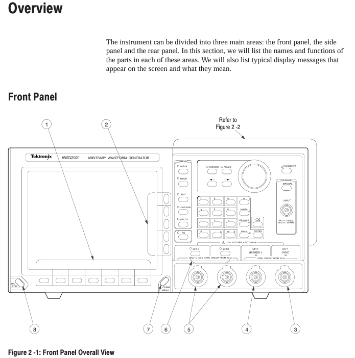
2. Key components of the front-end panel
Specific functional operation examples for component categories
MEAS key in function selection area: switch measurement function; F. G key: Switch to function generator mode and press F. G key to enter standard waveform settings such as sine/triangle/square wave
Menu Control Area MENU Column: SETUP (Parameter Configuration), MODE (Run Mode), EDIT (Editor), LOAD/SAVE (File Management), UTILITY (System Settings) Press the EDIT key to enter the initial menu for file editing
Universal knobs in the data operation area: adjust values/select files; Numerical keys (0-9/.+-): input parameters; Unit key (ns/MHz, etc.): Enter the "1"+"MHz" key to specify the unit and set the clock frequency to 1 MHz
Trigger control area TRIGGER INPUT: external trigger input (maximum ± 10 V ₚ₋ₚ); MANUAL key: Manually triggered. In Triggered mode, press the MANUAL key to trigger waveform output once
Output control area CH1/CH2 ON/OFF keys: switch channel output; SYNC/MARK output interface: Sync/Mark signal output. Press the CH1 ON/OFF button, and the LED will light up to indicate that the CH1 waveform output is turned on
Core functional module: Editor and menu configuration
1. Four core editors (EDIT menu)
(1) Waveform Editor (. WFM file)
Function: Create/edit waveform data, supports 3 display formats:
Graphic display: Visualize waveforms, support point drawing, smoothing (spline/linear interpolation), arithmetic operations (absolute value/integral/derivative).
Timing display: Display timing according to data bits (DATA 11-DATA 0), supporting the setting of - pattern (such as NRZ/NRZI encoding).
Table display: Display each point data in binary/hexadecimal/real form, supporting direct editing of numerical values.
Key operations: Select the editing area (left and right vertical cursor), perform cutting/copying/pasting, or insert other waveform files.
(2) Equation Editor (. QU file)
Function: Generate waveforms through mathematical equations, support 100 line equations, compile and generate WFM file.
Support functions: trigonometric functions (sin/cos), exponents (exp), logarithms (log/ln), random numbers (rnd), differentials (diff), integrals (integ), etc.
Example equation: range (0,1ms) sin (2 * pi * x) (generates a single period sine wave within 0-1ms).
(3) Sequence Editor (. SEQ file)
Function: Combine multiple waveform/sequence files and set the number of repetitions for each file (1-65535 times).
Operation process: Select a file from the directory → Set the number of repetitions → Generate a sequence, support "Show Overview" preview of combined waveforms.
(4) Automatic Step Editor (. AST file)
Function: Program waveforms and output parameters (clock/amplitude/filter) step by step, switch one step per trigger, supporting 100 steps.
Features: In AutoStep mode, the SETUP menu parameters cannot be modified, and the parameters between steps can be independently set (such as Step 1 amplitude of 2V, Step 2 amplitude of 3V).
2. Extended Editor (Option 09)
Editor Type Function Key Parameters
FFT editor for frequency domain editing, supporting fast Fourier transform/inverse transform window functions: 6 types including rectangle, Hanning, and Hamming; Filtering: low-pass/high pass/band-pass/bandstop
Convolutional waveform editor supports high-speed convolution/correlation operations with a maximum of 32000 data points, where the number of result points equals the sum of two waveform points
3. Key menu configuration
(1) SETUP menu (output parameter settings)
Parameter Category Configuration Options Value Range/Description
Clock source: Internal/External; Frequency (Internal) 10.00 Hz -250.0 MHz (4-digit accuracy)
Waveform Sequence (file selection) supports selecting waveform/sequence files WFM/. SEQ file, automatically loads corresponding parameters
CH1 Operation: Normal/AM/Add/External AM AM: CH1 × CH2; Add: CH1+CH2 (1/5 CH2 weight)
Filter Through/1/5/20/50 MHz suppresses high-frequency noise, such as 50 MHz filtering, which is suitable for high-frequency waveforms
Amplitude: Vertical axis full bias voltage of 0.05 V -5 V (50 Ω load, 1 mV step)
Offset Vertical axis offset voltage -2.5 V -+2.5 V (5 mV step size)
(2) MODE menu (operating mode)
Mode name function triggering conditions
Cont (continuous mode) continuously outputs waveforms without triggering, select and run
Triggered mode outputs a waveform every time it is triggered. External trigger (rising/falling edge) or MANUAL key is used
When the gate signal is valid, output waveform external signals (high/low level) or press and hold the MANUAL key
Burst mode: After triggering, output the specified number of waveform bursts 1-65535 times, triggered externally or with the MANUAL key
Waveform Advance switches to the next waveform every time it is triggered, ignoring the number of repetitions in the sequence file and cyclically outputting in order
Press AutoStep AST file step output, with independent parameters for each step and execution of one step per trigger, supporting 100 steps
Data Management and Transmission (LOAD/SAVE menu)
1. Storage medium and capacity
Storage Type Capacity Characteristics
Internal memory (RAM) up to 400 files lost due to power failure, used for temporary editing/output
NVRAM (non-volatile memory) 512KB, up to 400 files can be saved in case of power failure, suitable for long-term storage of critical files
3.5-inch floppy disk is compatible with MS-DOS format and supports directory hierarchy. It needs to be formatted first (UTILITY menu)
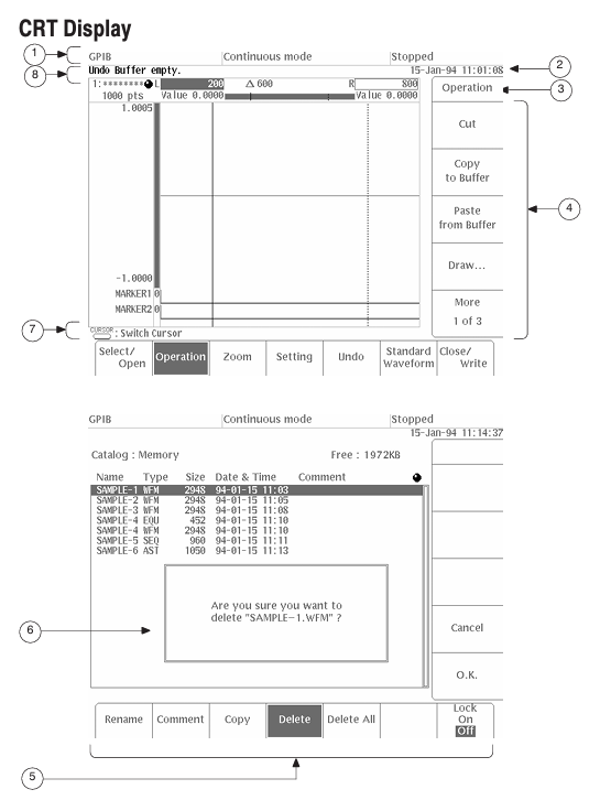
2. File loading/saving operations
Load file
Press the LOAD/SAVE key → select Device → select the target media (Disk/NVRam/GPIB).
Select Load → Select 'Load All' or individual file → Confirm loading into internal memory.
Save file
Press the LOAD/SAVE key → select Device → select the target medium.
Select Save → Select "Save All" or individual file → Optional ASCII format for external analysis.
3. GPIB direct transmission
Supported devices: Tek TDS series oscilloscope, HP 54600 series oscilloscope, etc. (refer to Table 3-19).
Operation steps:
Connect AWG2021 to the source device using GPIB cable.
Select Device → GPIB → Select Source Device (such as "Tek TDS CH1").
Select Load ->Automatically load waveform into internal memory (named as "TDSCH1. WFM").
Calibration and maintenance
1. Self calibration process
Trigger condition:
Regular: once every 90 days when the environment is stable (± 2 ℃); When the fluctuation is greater than 5 ℃, once every 30 days.
Manual: Press and hold the CAL key when turning on, or UTILITY → Calibration → Start.
Steps:
Disconnect all probes, the instrument displays "CALIBRATION...".
Internal calibration of ADC and reference source (approximately 2 minutes), complete display of "CAL PASS".
If 'CAL FAIL', check the ambient temperature (+18 ℃ -+28 ℃) and recalibrate.
2. Common troubleshooting
Possible causes and solutions for the fault phenomenon
No display/power adapter failure, fuse blown, replace with 12V/3A adapter; Check the 2A/250V fuse (Rear panel)
The waveform has no inflection point (such as the breakdown voltage test of the Zener transistor), the vertical sensitivity is insufficient, and the filter gear is improper. The vertical sensitivity is set to 1 μ A/div (leakage current measurement), and MAG X10 is turned on; Select a 50 MHz filter
GPIB transmission checksum error, loose cable, incorrect command format, replace GPIB cable (total length ≤ 20m); Confirm that the command termination symbol (EOI/LF) is consistent with the device
Appendix Key Content
Appendix A (Options and Accessories): Detailed description of hardware specifications and connection methods for options such as Option 02 (2-channel) and Option 03 (ECL output).
Appendix B (Performance Characteristics): Electrical characteristics (such as clock frequency accuracy ± 10 ppm), mechanical characteristics (weighing approximately 10kg), environmental characteristics (storage humidity 10% -90%).
Appendix C (Performance Verification): Includes testing procedures for clock frequency/amplitude accuracy/pulse response, etc., which require the use of a standard signal source and oscilloscope.
Appendix D (Sample Waveform Library): Provides formulas and parameters for preset waveforms such as Gaussian pulses, Lorentz pulses, DQPSK signals, etc.
- ABB
- General Electric
- EMERSON
- Honeywell
- HIMA
- ALSTOM
- Rolls-Royce
- MOTOROLA
- Rockwell
- Siemens
- Woodward
- YOKOGAWA
- FOXBORO
- KOLLMORGEN
- MOOG
- KB
- YAMAHA
- BENDER
- TEKTRONIX
- Westinghouse
- AMAT
- AB
- XYCOM
- Yaskawa
- B&R
- Schneider
- Kongsberg
- NI
- WATLOW
- ProSoft
- SEW
- ADVANCED
- Reliance
- TRICONEX
- METSO
- MAN
- Advantest
- STUDER
- KONGSBERG
- DANAHER MOTION
- Bently
- Galil
- EATON
- MOLEX
- DEIF
- B&W
- ZYGO
- Aerotech
- DANFOSS
- Beijer
- Moxa
- Rexroth
- Johnson
- WAGO
- TOSHIBA
- BMCM
- SMC
- HITACHI
- HIRSCHMANN
- Application field
- XP POWER
- CTI
- TRICON
- STOBER
- Thinklogical
- Horner Automation
- Meggitt
- Fanuc
- Baldor
- SHINKAWA
- Other Brands
- UniOP
- KUKA
- Iba
-
 ABB UFC921A101 Main Control Board
 -
 ABB UFC921A Main Control Unit
 -
 ABB UFC911B108 Drive Main Control Unit
 -
 ABB UFC911B106 Drive Main Control Unit
 -
 ABB UFC911B101 Drive Main Control Unit
 -
 ABB UFC765AE102 Drive Control Interface Board
 -
 ABB UFC762AE101 I/O and Communication Extension Board
 -
 ABB UFC760BE41 I/O and Communication Extension Board
 -
 ABB UFC760BE145 I/O and Communication Extension Module
 -
 ABB UFC721BE101 Fieldbus Communication Adapter Module
 -
 ABB UFC721AE101 3BHB002916R0101 Network Interface
 -
 ABB UFC718AE101 HIEE300936R0101 Communication Module
 -
 ABB UDC920BE01 3BHE034863R0001 Communication Module
 -
 GE IS420UCSCH1A-F-VO.1-A Controller Module
 -
 GE UCSC H1 IS420UCSCH1A Controller Station Card
 -
 ABB UCD240A101 3BHE022287R0101 Process Controller
 -
 ABB UCD224A103 Process I/O Module
 -
 ABB UCD224A102 Analog Input Module
 -
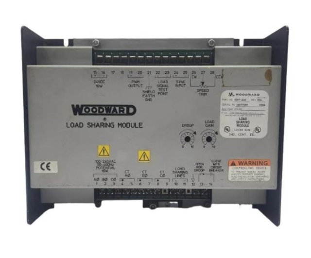 WOODWARD 9907-838 Load Sharing Module
 -
 B&R X20CP1485-1 Industrial PC CPU Module
 -
 ELAU MC-4/11/22/400 4-Axis Servo Drive
 -
 ELAU C600/10/1/1/1/00 Configurable Safety Relay
 -
 BENTLY 60R/SIM01 Proximitor Power Supply
 -
 BENTLY 60R/PPM01 Protection Processing Module
 -
 BENTLY 60R/PNL01 Operator Control Panel
 -
 BENTLY 60R/PIM01 Panel Interface Module
 -
 BENTLY 60R/INP07 Isolated DC Input Module
 -
 BENTLY 60R/INP01 4-Channel Analog Input Module
 -
 BENTLY 60R/CMM01 Communication Multiplexer Module
 -
 BENTLY 60R/CHA02 System Chassis Rack Enclosure
 -
 BENTLY 60R/CGW01 Condition Monitoring Gateway
 -
 Pacific Scientific P70360-SDN Servo Motor
 -
 HONEYWELL 05701-A-0284 Signal Conditioner
 -
 YOKOGAWA NFCP501-W05 Pressure Transmitter
 -
 ABB CI541V1 3BSE0146666R1 Control Interface
 -
 ABB DSTC176 57310001-KT Terminal Base Unit
 -
 ABB DSDP170K02 3BSE019925R1 Analog Input Module
 -
 ABB DSBC173 57310001-KH Terminal Base Unit
 -
 ABB DSAI130K01 5730-030-UC Thermocouple Input
 -
 ABB DSRF182 57310255-AL Relay Output Module
 -
 ABB SC520 3BSE003816R1 Compact PLC
 -
 ABB DSDP140A 57160001-ACT Analog Input Module
 -
 ABB DSAI130 57120001-P Analog Input Module
 -
 ABB SCYC55830 3AFE58063282 MCCB
 -
 Fireye 95DSS3-1CEX UV Flame Scanner
 -
 ABB DSDP170 57160001-ADF Analog Input Module
 -
 ABB CI532 3BSC140120R1 Communication Interface
 -
 ABB DSAO120A 3BSE018293R1 Analog Output Module
 -
 ABB CI869K01 3BSE049110R1 Ethernet Interface
 -
 ABB CI522A 3BSE018460R1 PROFIBUS DP Master
 -
 GUTOR OP6257 Rectifier Control Unit
 -
 Meggitt C327845-11 Gas Shutoff Valve
 -
 ABB SACO64D4 4-Pole Digital Annunciator Unit
 -
 ABB CI522AK04 3BSE018451R1 PROFIBUS DP Module
 -
 ABB DSAI130DK01 3BSE020828R1 Temperature Input Module
 -
 ABB CI546 3BSE012610R1 PROFIBUS DP Master Module
 -
 ABB SC510 3BSE003832R1 Compact PLC Controller
 -
 ABB CI540 3BSE001077R1 PROFIBUS DP Slave Module
 -
 ABB CI532V03 3BSE003828R1 AF 100 PROFIBUS DP Master
 -
 ABB DSBC172 57310256-EL Digital Input Terminal Base
 -
 Rexroth VT2000-5X Frequency Converter AC Drive
 -
 GE MAVS01L1AB0751D-140393N Soft Starter
 -
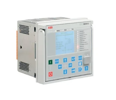 ABB REF615 HBFDACADNAA1BCN1XE Relay
 -
 ABB SACO16D1 1-Pole Digital Annunciator Unit
 -
 ABB UNITROL 1000 3BHE014557R0003 Static Excitation System
 -
 Woodward 8273-1011 Electro-Hydraulic Actuator
 -
 Eaton MC2-442-57CQB-1-2A Molded Case Circuit Breaker
 -
 Siemens 3AY1715-6L VS30029P VS30041 Auxiliary Contact Block
 -
 ABB PCD235B101 3BHE032025R0101 Digital I/O Control Module
 -
 Socapel PAM-R1R-H8F-AP-P V10800 Programmable Axis Manager
 -
 Rexroth VT-HNC100-1-23N-08-P-0 Digital Hydraulic Amplifier
 -
 Woodward 5448-890 SPM-D10 Digital Synchronizer
 -
 TDK-Lambda HWS1500-24 Industrial Power Supply
 -
 Land M2300/1100C-V Infrared Pyrometer
 -
 Lantronix 080-332-000-R Industrial Device Server
 -
 LED E14 3W Miniature LED Lamp
 -
 LEM LC100S/SP7 Hall Effect Current Sensor
 -
 Lenel LNL-1320 Dual Reader Interface Module
 -
 Lenze L5311 Industrial Control Module
 -
 Lenze EPZ-10203 Safety Controller
 -
 Lenze EPL10200 Industrial Drive Module
 -
 Lenze EPL-10200-XX Drive Controller
 -
 Lam Research 810-801237-021 Industrial Part
 -
 Lam Research 810-073479-215 Precision Part
 -
 Lam Research 853-001983-110 Assembly Data
 -
 Lam Research 810-017034-005 Semiconductor Part
 -
 Lambda LZS-A1500-3 AC-DC Power Module
 -
 Lambda LZS-1500-3 Industrial Power Supply
 -
 LAM 810-072907-005 Chamber Interface Control Module
 -
 LAM 810-068158-014 Semiconductor Process Control Module
 -
 LAM 810-800081-018 Vacuum System Interface Module
 -
 LAM 810-068158-013 Semiconductor Control Module
 -
 Leybold CM330 Vacuum Gauge Controller
 -
 Leybold 850-400-G1 Vacuum Pump Module
 -
 LIFTMASTER 71-1550B18LGH Electric Actuator
 -
 LKB Bromma 2211 Pressure Sensor
 -
 LLASERGAS AO2000 LS25 12944-E Gas Analyzer Module
 -
 Load Controls PH-3A Three-Phase Power Sensor
 -
 Ludlum 2401-P Pancake GM Survey Meter
 -
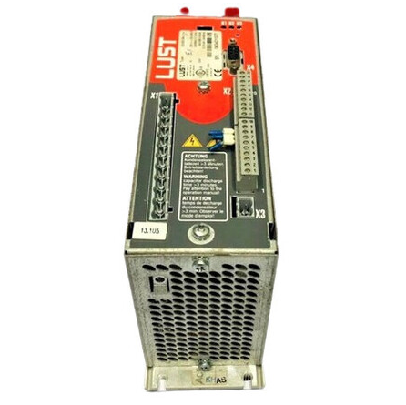 LUST VF1410LHFS41 AC Servo Drive
 -
 LUTZE UBE-FL/34M Terminal Block Contact
 -
 Marposs E78 Dynamic Balancing Controller
 -
 LENZE E84AVSCE1534VX0 Servo Drive Controller
 -
 LENZE EVF8212-E Frequency Inverter Drive
 -
 LENZE EA-4/10 Drive Expansion Module
 -
 LENZE BG10 Brake Module
 -
 LEUZE DDLS 200/200.1-50-M12 Data Link Data
 -
 LEUZE DDLS 200/200.2-50-M12 Optical Data
 -
 LEYBOLD TURBOVAC 361 Turbomolecular Pump
 -
 LEYBOLD TR211 Vacuum Controller Data
 -
 LEYBOLD SV40BI Rotary Vane Pump Specifications
 -
 LEYBOLD PR25 Vacuum Pressure Sensor Data
 -
 MARPOSS E9066 Precision Measurement Control Unit
 -
 MATROX Y7116-04 REV A Industrial Vision Processing Board
 -
 MATROX Y7116-01 REV A Industrial Video Processing Board
 -
 MCS SA1000 Industrial Signal Amplifier Module
 -
 MECS CS-1000 Control System Hardware Data
 -
 MECS UTX1010 Industrial Control Module
 -
 MECS UTX-1000A Industrial Module
 -
 MECS UTV-F2500HA High-Power Thyristor Data
 -
 MECS EXT-2 Advanced Expansion Interface
 -
 MECS EXT-1 Interface Extension Module
 -
 MECS CPU-1000 Industrial PLC Controller
 -
 MEN A201SR04 Embedded Computer
 -
 MERAK 681H10078 681K10078 681K10079 Control Modules
 -
 Mercury Step C-663 Stepper Motor Controller
 -
 MERLIN GERIN MX+0F 26948 Shunt Trip Release
 -
 MERLIN GERIN 32570 Miniature Circuit Breaker


