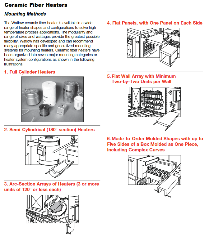
Watlow Ceramic Fiber Heater
-Chemical resistant coating
-Remote temperature monitoring is suitable for complex reactor structures, resistant to high temperature media, and safe and stable
Installation and usage specifications
(1) Preparation before installation
1. Environmental and spatial requirements
Temperature limit: The installation environment temperature should be between 0-100 ° C to avoid direct exposure to rainwater, oil stains, and corrosive gases.
Heat dissipation space: A ventilation space of ≥ 3 inches (76 mm) should be reserved around the heater to avoid heat accumulation.
Installation surface: It needs to be flat and heat-resistant, and the semi cylindrical/full cylindrical heater needs to ensure that the installation surface is tightly attached to the equipment.
2. Preparation of tools and accessories
Installation tools: torque wrench (recommended 8-20 in lbs range), Phillips # 3 screwdriver, compressed air (for cleaning).
Essential accessories: Ceramic fiber insulation blanket (CFBLKT series), thermocouple (K/J type, equipped with ceramic sleeve), semiconductor fuse (such as Bussmann 170M series).
Protective equipment: gloves, masks, goggles (to avoid inhaling ceramic fibers).
(2) Installation steps and key requirements
1. Fixed method (priority order)
Mechanical fixation: using pins, clamps, overlapping edge clamping or interlocking edges to avoid adhesion (unable to adapt to thermal expansion and contraction).
Splicing installation: When multiple units are spliced, reserve a 1/8-1/4 inch (3.2-6.4 mm) shrinkage gap, and fill it with loose ceramic fiber cotton after the first use.
Special form installation:
Semi cylindrical: fixed to the inner wall of the equipment with clamps to ensure a seamless fit.
Customized molding: Fix with high-temperature resistant bolts according to the design drawings to avoid cracking caused by uneven stress.
2. Wiring specifications
Wire selection: Copper wire, insulation level above 90 ° C, wire diameter selected according to current (≥ 1.5 mm ²/10A).
Terminal connection: Use crimped terminals, keep away from high temperature areas (≥ 6 in distance), torque 8-10 in lbs, to avoid loosening.
Grounding requirements: The grounding wire should be of the same specifications as the power line, connected to the protective grounding terminal of the equipment, and comply with NEC standards.
Fuse selection: Match according to the power of the heater, for example, a 65 A heater with a 100 A fuse (refer to Table 2-1 in the manual).
3. Thermocouple installation
Installation position: ≤ 1/16 in (1.6 mm) from the heating surface, preferably installed between components or in hot spot areas.
Fixed method: Fixed with ceramic sleeve to avoid direct contact with heating element (to prevent short circuit).
Wiring: The thermocouple wires are protected with ceramic sleeves and kept away from power lines to reduce interference.
(3) Usage and Maintenance Standards
1. First use operation
Pre firing treatment: When first powered on, heat up to 1600 ° F (871 ° C) at 50% power and hold for 24 hours to achieve stable fiber shrinkage.
Temperature monitoring: Real time monitoring of chamber temperature and external surface temperature to avoid overheating operation.
Gap filling: After pre firing, fill the joint gap with loose ceramic fiber cotton to improve the insulation effect.
2. Daily maintenance (cycle and content)
Maintenance cycle core content operation requirements
Monthly surface cleaning uses compressed air (below 0.2 MPa) to clean surface dust and avoid fiber accumulation
Quarterly wiring inspection: Re tighten the terminals and check if the insulation layer of the leads is aging (such as cracking or discoloration)
Half year insulation inspection to check if the ceramic fibers are damaged, and repair the damaged areas with a repair kit (CFPATCHKIT)
Annual performance calibration uses standard thermocouples to calibrate temperature display and check if power output is stable
3. Fault handling and safety precautions
Common troubleshooting:
Possible causes and solutions for the fault phenomenon
Slow heating, insufficient insulation, low power density selection, increase insulation blanket, replace with high power density model
Improper installation position of local overheating thermocouple, component damage, adjustment of thermocouple position, replacement of damaged heater
External temperature is too high, wall thickness is insufficient, there is no insulation blanket, add insulation blanket, replace thickened heater
The lead is burned out. The lead is too close to the heat source and the wire diameter is too small. Adjust the lead position and replace the thick wire diameter
Safety taboos:
Do not come into direct contact with high-temperature surfaces (working at temperatures greater than 200 ° C to avoid burns).
Do not use without temperature control equipment (requires Watlow Power Series controller, etc.).
It is prohibited to use non original accessories for repair (such as ordinary adhesives, which can release harmful substances at high temperatures).
Prohibited for use in conductive heating scenarios (such as direct contact with liquids or solid loads).

Accessories and Customization Services
- ABB
- General Electric
- EMERSON
- Honeywell
- HIMA
- ALSTOM
- Rolls-Royce
- MOTOROLA
- Rockwell
- Siemens
- Woodward
- YOKOGAWA
- FOXBORO
- KOLLMORGEN
- MOOG
- KB
- YAMAHA
- BENDER
- TEKTRONIX
- Westinghouse
- AMAT
- AB
- XYCOM
- Yaskawa
- B&R
- Schneider
- Kongsberg
- NI
- WATLOW
- ProSoft
- SEW
- ADVANCED
- Reliance
- TRICONEX
- METSO
- MAN
- Advantest
- STUDER
- KONGSBERG
- DANAHER MOTION
- Bently
- Galil
- EATON
- MOLEX
- DEIF
- B&W
- ZYGO
- Aerotech
- DANFOSS
- Beijer
- Moxa
- Rexroth
- Johnson
- WAGO
- TOSHIBA
- BMCM
- SMC
- HITACHI
- HIRSCHMANN
- Application field
- XP POWER
- CTI
- TRICON
- STOBER
- Thinklogical
- Horner Automation
- Meggitt
- Fanuc
- Baldor
- SHINKAWA
- Other Brands


