
Watlow Ceramic Fiber Heater
Watlow Ceramic Fiber Heater
Product Core Overview
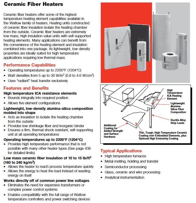
The Watlow ceramic fiber heater is a radiation type heater designed specifically for high-temperature scenarios. The core consists of an alumina silica ceramic fiber insulation layer and built-in heating elements, which have the characteristics of low quality, high insulation, and strong thermal shock resistance. Its maximum working temperature can reach 2200 ° F (1204 ° C), with a power density range of 5-30 W/in ² (0.8-4.6 W/cm ²). It only works through radiation heat transfer and can directly adapt to common power supply voltages without the need for transformers. It is widely used in industrial scenarios such as high-temperature furnaces, metal melting, semiconductor processing, and glass ceramic processing.
Core advantages:
High temperature adaptation: far exceeding the temperature limit of traditional heaters, suitable for extreme working conditions of 815-1204 ° C.
Efficient and energy-saving: Low quality insulation materials (10-15 lb/ft ³ density) heat up rapidly, and energy is concentrated on the load rather than self loss.
Flexible structure: Supports various forms such as flat, semi cylindrical, and fully cylindrical, and can customize multi-faceted integrated structures to adapt to complex installation environments.
Durable and reliable: inorganic adhesive and ceramic coating design, resistant to thermal cycling and chemical corrosion (except hydrofluoric acid, phosphoric acid, and strong alkali).
Product Structure and Core Configuration
(1) Differences in Heating Element Types and Technologies
The heater provides 5 core component configurations, with significant differences in power density, thermal efficiency, and applicable scenarios among different types. The specific comparison is as follows:
Key advantages of component type structure design, power density improvement, temperature adaptation, and typical applications
Embedded Sined: Sine shaped heating wire embedded inside ceramic fibers, divided into two subtypes: flat plate/V-shaped - with large insulation thickness and low heat loss
-Stable structure, resistant to mechanical impact
-Supporting long-term operation of medium to high power density, the V-type is 27% higher than the flat type, with a temperature range of 1500-2200 ° F (815-1204 ° C) for large-sized flat equipment, semi cylindrical furnace bodies (inner diameter>5 in), and fully cylindrical furnace bodies (inner diameter>4 in)
Exposed Sinusoidal Heating Wire: The sinusoidal heating wire is exposed on the surface of ceramic fibers and can be divided into two sub types: flat plate/V-shaped - with the smallest temperature difference between the component and the cavity, extending its lifespan
-The fastest heating/cooling speed
-The current carrying capacity is stronger, reducing the number of large furnace circuits by 20% compared to the flat plate type. The V-type has a large surface area heating surface, large inner diameter curved surface equipment, and requires fast thermal response scenarios at 1500-1800 ° F (815-982 ° C)
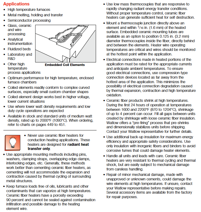
Embedded Coil: A coil shaped heating wire embedded in ceramic fibers, suitable for complex curved surfaces - fitting small customized chamber shapes
-High voltage and low current operation to reduce line losses
-Optimal insulation performance -1500-2000 ° F (815-1093 ° C) low power density, low duty cycle operating conditions, small tube furnaces, laboratory equipment
(2) Product Form and Specification Segmentation
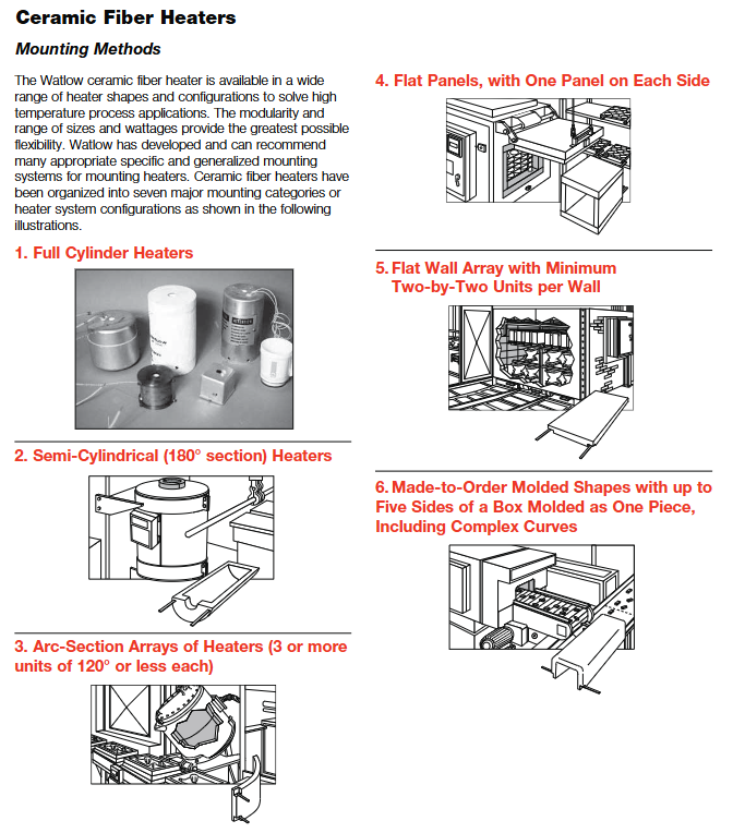
Watlow offers 4 basic forms and customized molding solutions, covering different installation spaces and chamber structure requirements. Each form has a clear size range and type division:
1. Flat panel heater (model prefix VF)
Type classification:
Type 5: Full area heating, no insulated edges, suitable for tight splicing scenarios.
Type 6: Side insulation, end heating to avoid side heat loss.
Type 7: End insulation, side heating, suitable for rectangular chambers.
Type 8: Full edge insulation, only heating in the middle area, precise temperature control.
Size range:
Heating area width (A): 4-36 in (102-914 mm)
Heating zone length (B): 6-36 in (152-914 mm)
Total width/length (including insulation): 1/16-1/8 inch (1.6-3.2 mm) larger than the heating area
Power and weight:
Power range: 275-7200 W
Weight: 0.3-16.7 lbs (0.14-7.6 kg), varies with size and type
2. Semi cylindrical heater (model prefix VS)
Type classification:
Type 1: Fully vestibule, with complete insulation at both ends.
Type 2: Left Vestibule, only insulated on the left side.
Type 3: Right Vestibule, with insulation only on the right side.
Type 4: No Vestibule, no end insulation, length consistent with the heating area.
Size range:
Inner diameter (A): 1/2-8 in (13-203 mm)
Heating length (B): 6-42 in (152-1067 mm)
Outer diameter (C): 4-6 inches (102-152 mm) larger than the inner diameter, with a standard wall thickness of 2 inches
Power and weight:
Power range: 750-9000 W
Weight: 0.23-15.6 lbs (0.1-7.1 kg), Type 1 due to the heaviest vestibule
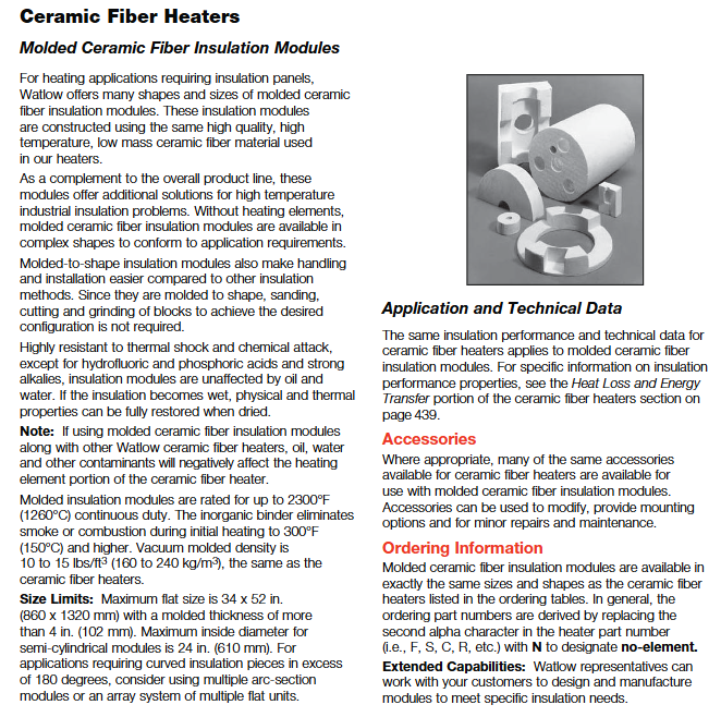
3. Full cylindrical heater (model prefix VC)
Core features: Integrated molding, no splicing gaps, optimal insulation effect.
Size range:
Inner diameter (A): 1/2-8 in (13-203 mm)
Length (B): 6-12 in (152-305 mm)
Outer diameter (C): 3-4 inches (76-102 mm) larger than the inner diameter
Power and weight:
Power range: 175-850 W
Weight: 0.14-0.71 lbs (0.06-0.32 kg), suitable for small tube heating
4. Customized molded heater
Adaptation scenarios: Multi sided integrated box (up to five sides), complex curves, polygons, curved arrays, and other non-standard structures.
Size restrictions:
Maximum tablet size: 34 × 52 in (860 × 1320 mm), thickness>4 in (102 mm)
Maximum semi cylindrical inner diameter: 24 in (610 mm)
Exceeding 180 ° surface: using multi arc splicing or flat array scheme
(3) Key feature options and enhanced configurations
1. Surface treatment and emissivity optimization
High emissivity coating: Black coating (part number CFBSC), emissivity close to 1.0, improves radiation heat transfer efficiency, and is suitable for scenarios that require rapid heating.
Hardening treatment: Rigid hardening agent (CFRGDPT/CFRGDGAL), used to repair cutting edges or enhance surface hardness to avoid handling damage.
2. Thermocouple installation plan
Embedded ceramic tube: available in two inner diameters of 0.140 in (3.6 mm) and 0.265 in (6.7 mm), with a length of 0.9-1.9 in, used for fixing thermocouples and achieving electrical isolation.
Component installation tube: Horizontal BTE closed end tube (part number CC405 series), installed between heating elements to accurately monitor element temperature and achieve over temperature protection.
3. Lead configuration and protection
Lead type:
Ribbon lead: Made of 601 alloy 600 material, with three output directions of A/B/C, default length of 12 inches, customizable from 0 to 42 inches.
Flexible lead: nickel material MGT insulation, Chromel ®- A/nickel alloy material, suitable for complex wiring scenarios.
Protective accessories: Ceramic sleeve (CC405 series), ceramic sleeve (CS45 series), used for high temperature protection when leads pass through metal walls.
Performance data and application adaptation
(1) Interpretation of Core Performance Curve
1. Temperature power density relationship
The product performance curve specifies the "safe working area": the intersection point of operating temperature and power density should be located on the left side of the curve, and the closer it is to the curve, the shorter the lifespan. Exceeding the curve may result in component burnout. Key conclusion:
At 2200 ° F (1204 ° C), the maximum safe power density is approximately 10 W/in ² (1.55 W/cm ²).
At 1800 ° F (982 ° C), high-power density models (V-shaped sine elements) can achieve 17-20 W/in ² (2.6-3.1 W/cm ²).
Below 1500 ° F (815 ° C), the power density can be increased to 25-30 W/in ² (3.9-4.6 W/cm ²).
2. Heating/cooling and power demand
Small fully cylindrical furnace (inner diameter 3/4-1 3/4 in):
Heating rate: It takes 10-20 minutes to rise from room temperature to 2000 ° F (1093 ° C).
Insulation power: Only 30-50% of rated power is required at 2000 ° F.
Medium sized sealed chamber (12 × 12 × 12 in):
Heating rate: It takes 20-30 minutes to rise from room temperature to 2000 ° F.
The temperature of the component is 100-200 ° F higher than the chamber temperature, and precise temperature control is required through thermocouples.
3. Insulation effect and external temperature
After being paired with a 6 lb/ft ³ (96 kg/m ³) ceramic fiber insulation blanket, the external surface temperature significantly decreases:
When the chamber temperature is 2200 ° F (1204 ° C), the external temperature of the 6-inch total wall thickness is ≤ 450 ° F (232 ° C).
When the chamber temperature is 1600 ° F (871 ° C), the external temperature of the 4-inch total wall thickness is ≤ 300 ° F (149 ° C).
(2) Typical application scenarios and adaptation solutions
Industry specific scene recommendation, product form, core configuration, key points, and value reflection
Metal processing melting furnace, insulation furnace, metal transmission line semi cylindrical/customized arc-shaped array - embedded V-shaped sine element
-High emissivity coating
-Thickened wall thickness (4-6 in), good heat resistance and insulation, reduces heat loss, suitable for metal high-temperature treatment
Semiconductor wafer CVD equipment, plasma processing furnace flat type 8/customized multi-faceted integrated embedded coil components
-Low power density (5-10 W/in ²)
-Clean and pollution-free, with strong thermal stability to avoid affecting process accuracy, suitable for vacuum/inert environments
Glass ceramic glass forming furnace, ceramic sintering furnace, fully cylindrical/flat plate splicing - exposed V-shaped sine element
-High power density (15-20 W/in ²)
-Multiple synchronous control systems ensure fast and uniform heating, high radiation efficiency, and improved consistency in product molding
Laboratory R&D small experimental furnace, analytical instrument full cylindrical/small flat plate embedded coil component
-Customized small size (inner diameter<2 inches)
-Quick start stop adaptation, compact size, fast heating and cooling, suitable for frequent testing needs
Chemical/Energy Reactor Heating, Catalyst Activation Custom Box/Arc - Full Edge Insulation Type 8
-Chemical resistant coating
-Remote temperature monitoring is suitable for complex reactor structures, resistant to high temperature media, and safe and stable
Installation and usage specifications
(1) Preparation before installation
1. Environmental and spatial requirements
Temperature limit: The installation environment temperature should be between 0-100 ° C to avoid direct exposure to rainwater, oil stains, and corrosive gases.
Heat dissipation space: A ventilation space of ≥ 3 inches (76 mm) should be reserved around the heater to avoid heat accumulation.
Installation surface: It needs to be flat and heat-resistant, and the semi cylindrical/full cylindrical heater needs to ensure that the installation surface is tightly attached to the equipment.
2. Preparation of tools and accessories
Installation tools: torque wrench (recommended 8-20 in lbs range), Phillips # 3 screwdriver, compressed air (for cleaning).
Essential accessories: Ceramic fiber insulation blanket (CFBLKT series), thermocouple (K/J type, equipped with ceramic sleeve), semiconductor fuse (such as Bussmann 170M series).
Protective equipment: gloves, masks, goggles (to avoid inhaling ceramic fibers).
(2) Installation steps and key requirements
1. Fixed method (priority order)
Mechanical fixation: using pins, clamps, overlapping edge clamping or interlocking edges to avoid adhesion (unable to adapt to thermal expansion and contraction).
Splicing installation: When multiple units are spliced, reserve a 1/8-1/4 inch (3.2-6.4 mm) shrinkage gap, and fill it with loose ceramic fiber cotton after the first use.
Special form installation:
Semi cylindrical: fixed to the inner wall of the equipment with clamps to ensure a seamless fit.
Customized molding: Fix with high-temperature resistant bolts according to the design drawings to avoid cracking caused by uneven stress.
2. Wiring specifications
Wire selection: Copper wire, insulation level above 90 ° C, wire diameter selected according to current (≥ 1.5 mm ²/10A).
Terminal connection: Use crimped terminals, keep away from high temperature areas (≥ 6 in distance), torque 8-10 in lbs, to avoid loosening.
Grounding requirements: The grounding wire should be of the same specifications as the power line, connected to the protective grounding terminal of the equipment, and comply with NEC standards.
Fuse selection: Match according to the power of the heater, for example, a 65 A heater with a 100 A fuse (refer to Table 2-1 in the manual).
3. Thermocouple installation
Installation position: ≤ 1/16 in (1.6 mm) from the heating surface, preferably installed between components or in hot spot areas.
Fixed method: Fixed with ceramic sleeve to avoid direct contact with heating element (to prevent short circuit).
Wiring: The thermocouple wires are protected with ceramic sleeves and kept away from power lines to reduce interference.
(3) Usage and Maintenance Standards
1. First use operation
Pre firing treatment: When first powered on, heat up to 1600 ° F (871 ° C) at 50% power and hold for 24 hours to achieve stable fiber shrinkage.
Temperature monitoring: Real time monitoring of chamber temperature and external surface temperature to avoid overheating operation.
Gap filling: After pre firing, fill the joint gap with loose ceramic fiber cotton to improve the insulation effect.
2. Daily maintenance (cycle and content)
Maintenance cycle core content operation requirements
Monthly surface cleaning uses compressed air (below 0.2 MPa) to clean surface dust and avoid fiber accumulation
Quarterly wiring inspection: Re tighten the terminals and check if the insulation layer of the leads is aging (such as cracking or discoloration)
Half year insulation inspection to check if the ceramic fibers are damaged, and repair the damaged areas with a repair kit (CFPATCHKIT)
Annual performance calibration uses standard thermocouples to calibrate temperature display and check if power output is stable
3. Fault handling and safety precautions
Common troubleshooting:
Possible causes and solutions for the fault phenomenon
Slow heating, insufficient insulation, low power density selection, increase insulation blanket, replace with high power density model
Improper installation position of local overheating thermocouple, component damage, adjustment of thermocouple position, replacement of damaged heater
External temperature is too high, wall thickness is insufficient, there is no insulation blanket, add insulation blanket, replace thickened heater
The lead is burned out. The lead is too close to the heat source and the wire diameter is too small. Adjust the lead position and replace the thick wire diameter
Safety taboos:
Do not come into direct contact with high-temperature surfaces (working at temperatures greater than 200 ° C to avoid burns).
Do not use without temperature control equipment (requires Watlow Power Series controller, etc.).
It is prohibited to use non original accessories for repair (such as ordinary adhesives, which can release harmful substances at high temperatures).
Prohibited for use in conductive heating scenarios (such as direct contact with liquids or solid loads).
Accessories and Customization Services
(1) List and purpose of core accessories
Recommended accessory categories, models, functions, purposes, and applicable scenarios
Insulation accessories CFBLKT1/4 and CFBLKT1 enhance insulation effect and reduce external temperature in all scenarios, especially in high-temperature conditions
CC405 series ceramic sleeve fixed thermocouples related to thermocouples, electrical isolation temperature monitoring requirements
Repair accessories CFPATCHKIT repair kit for small area damage repair (including ceramic powder+coating), repair after transportation or installation damage
Hardening protection CFRGPPT hardener enhances cutting edge hardness to avoid mechanical damage, customized forming heater edge protection
Lead protection CS45 series porcelain sleeve protects leads passing through metal walls, and high-temperature resistant leads need to penetrate furnace walls
High emissivity coating CFBSC black coating enhances radiation efficiency and accelerates heating in scenarios requiring rapid thermal response
(2) Customized service process and scope
1. Customization scope
Customized forms: non-standard sizes, multi-faceted integrated box shapes, complex curves, curved arrays, etc.
Performance customization: special power density (>30 W/in ²), high temperature resistance (>2200 ° F), corrosion-resistant coating.
Function customization: special lead direction, integrated thermocouple mounting base, multi zone independent temperature control.
2. Customization process
Requirement submission: Provide operating parameters (temperature, power, chamber size), installation method, and drawings (if any).
Scheme design: Watlow engineers provide product drawings and performance parameter tables to confirm feasibility.
Sample testing (optional): When customizing large quantities, samples can be made first to verify performance.
Production delivery: Standard customization cycle is 3-4 weeks, urgent orders take 1-2 weeks.
- OMRON
- ABB
- General Electric
- EMERSON
- Honeywell
- HIMA
- ALSTOM
- Rolls-Royce
- MOTOROLA
- Rockwell
- Siemens
- Woodward
- YOKOGAWA
- FOXBORO
- KOLLMORGEN
- MOOG
- KB
- YAMAHA
- BENDER
- TEKTRONIX
- Westinghouse
- AMAT
- AB
- XYCOM
- Yaskawa
- B&R
- Schneider
- KONGSBERG
- NI
- WATLOW
- ProSoft
- SEW
- ADVANCED
- Reliance
- TRICONEX
- METSO
- MAN
- Advantest
- STUDER
- DANAHER MOTION
- Bently
- Galil
- EATON
- MOLEX
- DEIF
- B&W
- ZYGO
- Aerotech
- DANFOSS
- Beijer
- Moxa
- Rexroth
- Johnson
- WAGO
- TOSHIBA
- BMCM
- SMC
- HITACHI
- HIRSCHMANN
- Application field
- XP POWER
- CTI
- TRICON
- STOBER
- Thinklogical
- Horner Automation
- Meggitt
- Fanuc
- Baldor
- SHINKAWA
- Other Brands
- UniOP
- KUKA
- Iba
- Beckhoff
-
 Basler Electric DECS-200-1L Digital Excitation Control System
 -
 Basler DECS125-15-B2C1 Excitation Control
 -
 Basler 9507900205 SSR Retrofit Voltage Regulator
 -
 Basler BE2000E Digital Voltage Regulator
 -
 Basler BE1-GPS Generator Protection System
 -
 Basler DECS-250-CN1CN1N Digital Excitation Control
 -
 Basler DGC-2020 Genset Controller
 -
 Basler BE1-81O UT3ED1LA7N0F Frequency Relay (Variant)
 -
 Basler BE1-81O UT3EE1YA9S0F Frequency Relay (Variant)
 -
 Basler BE1-81O Over/Under Frequency Relay
 -
 Basler DECS125-15 Digital Excitation Control
 -
 Basler Electric BE1-951 Overcurrent Protection System
 -
 Basler Electric BE1-700V Digital Protective Relay
 -
 Basler Electric APR63-5 Automatic Voltage Regulator
 -
 Basler Electric BE1-851 Overcurrent Protection System
 -
 Basler Electric DECS-250-LN1SN1N Excitation Control
 -
 Basler Electric BE1-87T Transformer Differential Relay
 -
 Basler Electric DECS-200-1L Excitation Control System
 -
 Basler Electric 9310300100 DECS-300 Excitation Control
 -
 Basler Electric SSE-N 125-4.5KW Shunt Exciter Regulator
 -
 Basler Electric DGC-2020HD-5NS1DNSBA Genset Controller
 -
Basler Electric BE1-81-O/UT3EE1JB7N1F Frequency Relay
-
 Basler Electric BE1-81T1EE1WA0N1F Frequency Relay
 -
 Basler Electric BE1-25M1EA6PN5R1F Sync-Check Relay
 -
 Basler Electric BE1-GPS Generator Protection System
 -
Basler Electric DECS-250-LN1SN1N Excitation Control Rev V
-
 Basler Electric DECS-250-CN2CN1N Excitation Control
 -
 Basler Electric BE1-50/51B-207 Overcurrent Relay
 -
Basler Electric DECS-300-C0N0 Excitation Control System
-
Basler Electric DECS-200 Digital Excitation Control System
-
Basler Electric DECS-250-LN1CN1N Excitation Unit
-
Basler Electric DECS-250 LN2SA1D Excitation Unit Specs
-
Basler Electric BE1-87T Transformer Relay Review
-
Basler Electric BE1-11 Protection System
-
Basler Electric BE1-GPS100-E4N1H1N Protection System
-
 Allen-Bradley 442G-MABH-R Safety Module
 -
 Beckhoff CX1030-0111 PLC Assembly Profile
 -
 FANUC IC693CPU364 PLC Module
 -
 Orange Denmark Type 200816 220 PLC Specs
 -
 OMRON C200H-SNT31 Sysmac PLC Module
 -
 Allen Bradley 20AB022A3AYNANC0 PowerFlex 70
 -
 OMRON C200HW-PCU01 Position Control Unit
 -
 ABB AO845A-eA Analog Output Module
 -
 OMRON CJ1M-CPU22 CPU Unit
 -
 Allen Bradley 100-E265ED11 Contactor
 -
 Honeywell 51304511-100 Interface Module
 -
 SOLEXY BXF3S0101N0018 Gateway Module
 -
 OMRON CJ2H-CPU65 CPU Unit
 -
 Automation Direct GS2-45P0 AC Drive
 -
 M68-2000 2-Axis Motion CNC Controller
 -
 OMRON CJ1M-CPU11 V3.0 PLC CPU Unit
 -
 OMRON CJ1W-NC413 4-Axis Positioning Controller
 -
 OMRON 3G2A3-PRO16 Programming Console HMI
 -
 Siemens 3VT8440-2AA04-2GA2 Molded Case Circuit Breaker
 -
 Siemens 3RT5045 Contactor Series
 -
 OMRON C200HS-CPU01-E SYSMAC PLC Controller
 -
 OMRON C500-NC103-E Positioning Control Unit
 -
 OMRON CJ1W-TC001 Temperature Control Unit
 -
 OMRON NJ301-1100 NJ-PA3001 PLC System EtherCAT
 -
 Pilz 773100 M1P Safety Relay Base Unit
 -
 Siemens SINUMERIK 840D SL NCU 720.3B with PLC 317-3 PN/DP
 -
 Siemens 6AV6618-7GD01-3AB0 HMI Panel
 -
 OMRON F150-C15E-3 Vision Mate Controller PLC Overview
 -
 Mitsubishi MELSEC A Series PLC System A63P A3ACPU A616AD A68RD3
 -
 M68-2000 2 Axis Motion Controller SCE SERVO CNC
 -
 OMRON FZ-S2M PLC Camera Vision System
 -
 VISOLUX SLVA-4K PLC Module from Elektronik GmbH
 -
 OMRON CJ1M-CPU23 V2.0 PLC CPU Unit
 -
 ABB AI86-16CHF PCB Card 5761751-9 B Specifications
 -
 Allen-Bradley 100-D140ZJ22L Contactor Overview
 -
 Merlin Gerin PB80 PLC Rack
 -
 WEIR WE203 Power Supply PLC
 -
 OMRON NX-TS3102 Temperature Input Unit
 -
 Siemens 6ES7146-6FF00-0AB0 I/O Module
 -
 Fanuc A16B-3300-0057 Circuit Board
 -
 OMRON CJ1W-IDP01 Input Module
 -
 Siemens 6FX2007-1AD13 Handheld Unit
 -
 Gems EM54 PLC Module PCB
 -
 Beckhoff CX2030-0121 Embedded PC CPU
 -
 OMRON NJ301-1100 Machine Automation Controller
 -
 Biesse Rover CNI PLC 2153 030 7146.30 Numerical Control Module
 -
 OMRON CJ1W DA08V Analog Output Module
 -
 OMRON CS1D ETN21D Ethernet Module
 -
 Allen Bradley 1768 L43 CompactLogix Controller
 -
 Schneider TWDLMDA40DTK Twido PLC Module
 -
 Mitsubishi NZ2EX2B 60AD4 Analog Input Module
 -
 OMRON NS8 TV00B V2 Touch Display Panel
 -
 Mitsubishi AY71 CMOS TTL Output Module
 -
 OMRON C500 CPU11 E Processor Module
 -
 OMRON CJ1W PTS51 Temperature Input Module
 -
 Siemens 6SL3100-1DE22-0AA1 600V DC Supply
 -
 OMRON CJ1M-CPU23 PLC CPU 9‑Pin Serial
 -
 Schlumberger IMT4N 24‑250VAC 48‑230VAC PLC Timer
 -
 OMRON CJ1M-CPU22 PLC CPU Unit V2.0
 -
 Allen‑Bradley 2711P-B7C6D2 Touch Screen PanelView
 -
 ADSP-2181KST-160 Analog Devices DSP IC Specs
 -
 Schneider LC1F400 400A Contactor Specifications
 -
 Yaskawa SGDH-10DE-OY 1kW 400V Servo Drive
 -
 Schneider TM262L10MESE8T M262 PLC 5ns Inst
 -
 Mitsubishi AA104VJ05 10.4in LCD Panel Specs
 -
 Allen Bradley 1761-L32BWA MicroLogix 1000 PLC
 -
 Siemens 6ES7431-7KF00-0AB0 Analog Input Module
 -
 Allen Bradley 1769-OB16 Output Module
 -
 Siemens 6ES7131-1BL12-0XB0 Input Module
 -
 Beckhoff EP7041-3002 EtherCAT Box Module
 -
 Siemens RK7243-2AA30-0XB0 Communication Module
 -
 Siemens 4AM5742-8DD40-0FA0 Transformer
 -
 Siemens 3TK2834-1BB40 Safety Relay
 -
 Brother BAS 311 Sewing Machine Circuit Board
 -
Yaskawa SGDH-10DE-OY Servo Driver
-
 OMRON C60H C6DR DE V1 Sysmac PLC
 -
 MITSUBISHI ELECTRIC A2ACPU21 S1 CPU Module
 -
 ABB BAILEY INNPM12 Network Process Module
 -
 HONEYWELL 620 0073C IPC PLC Module
 -
 Mitsubishi 15050 PR02B PLC Circuit Board
 -
 SIEMENS 6SY7000 0AC37 Drive Control Module
 -
 OMRON TJ2 ECT16 Traxial EtherCAT Controller
 -
 GE Fanuc IC698PSD300D Power Supply Module
 -
 Texas Instruments Series 505 16 Position Base
 -
 OMRON YASKAWA SGDH 10DE OY Servo Drive
 -
 Allen‑Bradley 440G-MT Safety Interlock Switch Specs
 -
 Rubycon PD27A 24V 8A Power Supply Module
 -
 SK-H1-GDB1-F11D PLC Gate Driver Board Kit
 -
 VIPA 441-4UA14 451-4UA14 PLC Module Rack
 -
 Mitsubishi FX5U-80MT ESS PLC Controller Specs
 -
 Mitsubishi Q64TCRTN Temperature PLC Module
 -
 GE 1C31170G Rev10 PLC Circuit Board Module
 -
 Schneider TWDLMDA40DTK PLC Controller Module


