
Emerson DeltaV SIS Logic Solver (SLS1508)
The world's first intelligent SIS logic solver: communicates with intelligent field devices through the HART protocol to diagnose faults in field instruments and final control components in advance (according to research, such faults account for more than 85% of SIS faults), avoiding false tripping, improving process availability, and reducing full lifecycle costs.
Emerson DeltaV SIS Logic Solver (SLS1508)
Core positioning and core advantages
The DeltaV SIS Logic Solver (SLS1508) is the core component of Emerson's Intelligent Safety Instrumented Systems (SIS), designed specifically for industrial process safety protection and meeting SIL 1-3 safety functional requirements. Its core advantages can be summarized into six key features:
The world's first intelligent SIS logic solver: communicates with intelligent field devices through the HART protocol to diagnose faults in field instruments and final control components in advance (according to research, such faults account for more than 85% of SIS faults), avoiding false tripping, improving process availability, and reducing full lifecycle costs.
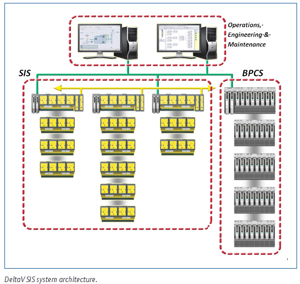
Integrated but independent with the control system: strictly follow safety standards, use dedicated hardware, software, and networks to implement safety functions, and eliminate the impact of common cause failures; Simultaneously achieve seamless integration of configuration, maintenance, and operating environment at the workstation level, balancing security and usability.
Easy to comply with IEC 61511 standard: provides strict user management functions, automatically verifies data for changes initiated by the human-machine interface (HMI) (such as trip limit modification), ensures accurate data writing into the target logic solver, and meets the strict requirements of the standard for change control.
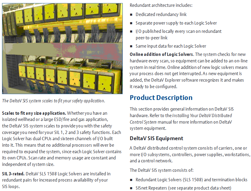
Suitable for any scale of application: Whether it is an isolated wellhead or a large emergency shutdown (ESD)/fire and gas system, it can be flexibly expanded to cover SIL 1-3 safety functions; Each logic solver is equipped with dual CPUs and 16 I/O channels, allowing for system expansion without the need for additional processors. The scanning rate and memory usage are not affected by system size and remain stable.
SIL 3 certification and redundant architecture: The SLS1508 logic solver meets SIL 3 application requirements with a single unit, and the availability is higher when installed in pairs with redundancy; The redundant architecture includes dedicated redundant links, independent power supply, I/O redundant peer-to-peer links for real-time release, and dual machine shared input data to ensure reliable system operation.
Support for online addition of logic solvers: The system automatically detects new hardware every scanning cycle and can add devices to the online system in real-time without interrupting the process; Once the newly added device is recognized by DeltaV Resource Manager, it can be directly configured, greatly improving the flexibility of system expansion.
Core components and functional details of the product
(1) Core hardware components and system architecture
Component Name Function Description Key Features
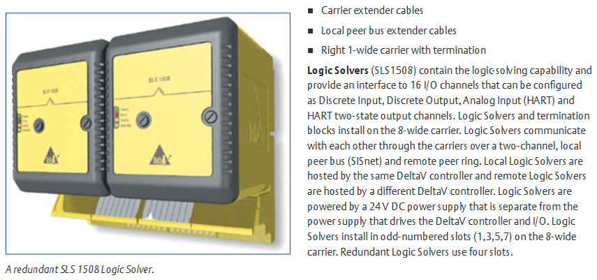
SLS1508 logic solver core safety logic operation unit, provides I/O interface with built-in dual CPU, 16 configurable I/O channels (discrete input/output, analog input (HART), HART dual state output), supports single SIL 3 application, and occupies 4 slots for redundant paired installation
The redundant terminal block connects the on-site wiring and logic solver to adapt to the SLS1508 redundant architecture, enabling redundancy without the need for additional control strategy configuration. The system automatically identifies redundant pairs
SISnet repeater extends the communication range of SISnet and realizes remote logic solver communication through fiber optic ring network. It is divided into two independent fiber optic rings, primary and backup. Please refer to the separate product manual for details
The carrier extension cable extends the local bus power and signal connection between 8-wide carriers, ensuring signal transmission between the controller, logic solver, and SISnet repeater
Local peer-to-peer bus extension cable extends SISnet communication between logic solvers on different carriers, supports interconnection of logic solvers across carriers, and builds a local SISnet network
The wide terminal carrier terminates the local peer-to-peer bus installed at the end of the carrier chain, providing SISnet bus terminal matching to ensure stable communication
The 8-width carrier carries logic solvers, SISnet repeaters, and other components. The logic solvers are installed in odd numbered slots (1/3/5/7) and support connecting multiple carriers through expansion cables
(2) Communication Network Design
Control Network: Implement communication between DeltaV network nodes, as detailed in the DeltaV Digital Automation System Installation Manual.
Local Bus: connects DeltaV controllers with logic solvers, SISnet repeaters, and transmits control and configuration signals.
Local Peer to Peer Bus (SISnet): a dual channel bus where logic solvers communicate with each other and with local SISnet repeaters through a carrier, and the same message is broadcasted on both channels; The two ends of the bus need to be terminated (the left end through a 2-wide power/controller carrier, and the right end through a 1-wide terminal carrier), and the repeater can be flexibly installed at any position on the bus.
Remote Peer Ring: SISnet repeaters hosted by different controllers communicate through fiber optic ring networks. Local repeaters aggregate global variable messages and transmit them along the ring network. Receiver repeaters broadcast and forward them on the local SISnet, while global messages are transmitted only once along the ring network. The primary and backup repeaters form independent fiber optic rings.
(3) Unique redundancy mechanism
Redundant operation mode: The redundant SLS1508 dual machine always runs in parallel, reading I/O inputs, executing safety logic, and driving outputs, without distinction between master and backup/master-slave; Only one (Active state, indicator light on) communicates with the workstation and SISnet, while the other (Standby state) only connects to SISnet.
Fault handling: When a single machine detects a fault, it automatically enters a failure state, and all output channels are powered off, but it does not affect the operation of another machine (continuing to read and write I/O, executing logic), and redundant switching is completely undisturbed; In safe areas, faulty modules can be replaced with electricity, while in hazardous areas, specific installation procedures must be followed.
Integrity alarm: Real time monitoring of redundant pair status, triggering alarm scenarios including: hardware failure of logic solver, communication failure between logic solver and SISnet, communication failure between redundant pairs, communication failure between logic solver and DeltaV controller, and removal of logic solver from carrier; Alarm information and device status can be viewed in the diagnostic browser.
Automatic verification testing: Redundancy can be configured for automatic verification testing. After setting the testing interval, the system will automatically execute and issue a warning to the operator before testing to ensure the effectiveness of safety functions.
(4) Sequence of Events (SOE) function
Basic function: Automatically generate events when executing function blocks during the module scanning cycle, with a timestamp resolution of<1ms, and record them in the event log in the order of occurrence; Standard functional blocks (input block, voting block, cause and effect block, etc.) can automatically generate events (such as I/O faults, trip limit triggering, first output signal) without special configuration, and record the simulated values and triggering conditions during tripping.
First out positioning: When the factory emergency stops, the "first out trip" signal in the event log can be filtered to quickly locate the first input that triggers the trip, simplifying fault diagnosis.
High resolution extension: If higher temporal resolution (0.25ms) is required, the channel can be simultaneously connected to SLS1508 and DeltaV discrete input SOE cards.
Hardware specifications and I/O channel parameters
(1) General Environment and Physical Specifications
1. SLS1508 Universal Environment Specification
Category parameter details
Working temperature -40~70 ° C (-40~158 ° F), long-term high-temperature operation shortens lifespan
Storage temperature -40~85 ° C (-40~185 ° F)
Relative humidity 5%~95% (no condensation)
Pollutant level ISA-S71.04-1985 G3 level (with conformal coating)
Protection level IP20
Hazardous Area Certification: European EMC Directive (EN61326-1, Criterion A), NAMUR NE21 EMC Requirements, Low Voltage Directive (IEC 61010-1), FM Class I Div 2 (Groups A-D, T4, No Arc) ATEX 3 G EEx IIC-nA T4(EN50021:1999)、CSA 1010
Anti impact 10g half sine wave (continuous for 11ms)
Vibration 5-16Hz (1mm peak to peak), 16-150Hz (0.5g)
2. SLS1508 Physical and Electrical Specifications
Project parameter details
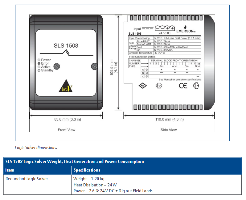
Input power supply 24V DC ± 20%, 1.0A (basic power consumption)+on-site power supply (total power consumption 5.0A); Suggest using an independent power supply with DeltaV controller/I/O
The maximum on-site power supply is 4A (actual value depends on channel type and on-site equipment)
Isolation level: Each channel is optically isolated from the system (1500VDC factory test), and there is no isolation between channels
No local bus current
Installation method: SIS (yellow) terminal block on a wide carrier with odd numbered slots; Redundant occupation of 4 slots
Redundancy for weight 1.20kg
Redundancy for heat consumption of 24W
Redundancy for 24V power consumption DC@2A +Digital output on-site load
Dimensions (Front/Side) 83.8mm (3.3 inches)/110.0mm (4.3 inches)

(2) Detailed parameters of I/O channels
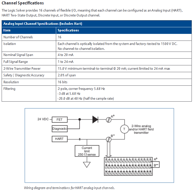
1. Analog input channel (including HART)
Project parameters
Number of channels 16
Isolate each channel from the system's optical isolation (1500VDC test), with no isolation between channels
Nominal signal range 4~20mA
Full signal range 1-24mA
When the 2-wire transmitter is powered by 20mA, the minimum voltage between terminals is 15.0V, and the maximum current limit is 24mA
2.0% of the safety/diagnostic accuracy range
Resolution 16 bits
Filter 2nd order, cut-off frequency 5.68Hz (-3dB), at 40Hz (1/2 of sampling rate) -20.0dB
2. HART dual state output channel
Project parameters
Number of channels 16
Isolate each channel from the system's optical isolation (1500VDC test), with no isolation between channels
The nominal signal range is 20mA for conduction and 0 or 4mA for shutdown (configurable)
Full signal range 0~24mA
5.0% of the safety/diagnostic accuracy range
Resolution of 12 bits
Compliant voltage 20mA@600 Ω load
Triggered when the open-loop detection output deviates from the configured value by 15% and the current is less than 1.0mA
3. Discrete input channel
Project parameters
Number of channels 16
Isolate each channel from the system's optical isolation (1500VDC test), with no isolation between channels
Conductivity detection ≥ 2mA
Shutdown detection ≤ 1.65mA
The input impedance is about 1790 Ω
Input compatibility NAMUR sensor (12V), dry contacts, dry contacts with terminal resistors
Line fault detection (short circuit, optional) with resistance<100 Ω and current>6mA
Line fault detection (open circuit, optional) with current<0.35mA when resistance>40k Ω
The fault detection configuration requires channel level activation, and the dry contact requires an external 12k Ω parallel resistor (open circuit detection) and a 2.4k Ω series resistor (short circuit detection). The NAMUR sensor does not require an external resistor
4. Discrete output channels
Project parameters
Number of channels 16
Isolate each channel from the system's optical isolation (1500VDC test), with no isolation between channels
Output voltage: On site power supply voltage -2V
On site power supply with continuous 0.5A per channel, maximum 4.0A per card
Output load 56~3500 Ω
Turn off leakage current open-loop test on: 7.8mA; open-loop test off: typical 4.5 μ A, maximum 10 μ A
Short circuit protection current limit typical 2.0A
Line fault detection (short circuit): Under 24V DC on-site power supply, the resistance is less than 5 Ω for more than 1 second
Line fault detection (open circuit): Under 24V DC on-site power supply, resistance>25k Ω (open circuit detection),<3.5k Ω (no open circuit detection)
Pulse testing is recommended to be enabled (apply 1ms of 24V DC pulse every 50ms), and devices such as solid-state relays that do not support it can be disabled
Ordering Information and Preconditions
(1) Core Product Order List
Product Description Model
DeltaV SLS1508 Redundant Logic Solver (including Terminal Block) VS3202
1 wide SISnet terminal component (including right expansion card and 2 terminal resistors) VS6051
SIS database extension VS1508
8-width carrier with expansion cable assembly (including left and right expansion cards, 2 logic solver communication buses coaxial, 1 carrier backplane communication cable) VE4050E1C2
2 Wide Carrier (Improved Type, Including Bus Terminal) VE3051C0
(2) Pre requirements
Software version: DeltaV v8.3 or above is required.
2-Width Power/Controller Carrier: Upgraded version after 2004 (with white rectangular markings on the board, located between the power module and MD controller), model KJ4001X1-BA3 and above; The old version (marked with white dots) does not support downloading logic solver programs.
MD controller: Model must be 12P2093X082 or above, early models do not support DeltaV SIS system.
- OMRON
- ABB
- General Electric
- EMERSON
- Honeywell
- HIMA
- ALSTOM
- Rolls-Royce
- MOTOROLA
- Rockwell
- Siemens
- Woodward
- YOKOGAWA
- FOXBORO
- KOLLMORGEN
- MOOG
- KB
- YAMAHA
- BENDER
- TEKTRONIX
- Westinghouse
- AMAT
- AB
- XYCOM
- Yaskawa
- B&R
- Schneider
- KONGSBERG
- NI
- WATLOW
- ProSoft
- SEW
- ADVANCED
- Reliance
- TRICONEX
- METSO
- MAN
- Advantest
- STUDER
- DANAHER MOTION
- Bently
- Galil
- EATON
- MOLEX
- DEIF
- B&W
- ZYGO
- Aerotech
- DANFOSS
- Beijer
- Moxa
- Rexroth
- Johnson
- WAGO
- TOSHIBA
- BMCM
- SMC
- HITACHI
- HIRSCHMANN
- Application field
- XP POWER
- CTI
- TRICON
- STOBER
- Thinklogical
- Horner Automation
- Meggitt
- Fanuc
- Baldor
- SHINKAWA
- Other Brands
- UniOP
- KUKA
- Iba
- Beckhoff
-
 OMRON B7AM-8B16 I/O Terminal Block
 -
 Fanuc A06B-6110-H026 Power Supply Module
 -
 Schneider TSXETG3021 Ethernet Gateway
 -
 OMRON CS1W-CLK21-V1 Controller Link Unit
 -
 NP1W6406T-Z704 PLC I/O Module
 -
 OMRON CJ1W-DA08C Analog Output Module
 -
 Yaskawa 3G3HV-A4022-CE AC Drive
 -
 OMRON NB7W-TW01B CP1L-EL20DR-D Power Panel
 -
 OMRON C500-NC103-E Position Control Unit
 -
 Steag Hamatech PLC DCS Servo Control System
 -
 Siemens 6SN1123-1AA00-0DA1 Power Supply Module
 -
 GE IC693CHS391H CPU & AD693CMM301A PLC Module
 -
 Siemens 6FC5303-0AF23-1AA1 PLC Control Panel
 -
 Square D CM4000T PowerLogic Circuit Monitor J1 F16
 -
 Siemens 6FX5002-5DG10-1BA0 MOTION-CONNECT 500 Cable
 -
 Schmersal SRB324ST 101195504 Safety Relay 24V
 -
 Mitsubishi 15050-PR02A PLC Circuit Board Module
 -
 OMRON CQM1-AD041 Analog Input PLC Module
 -
 Beckhoff EL5042 EtherCAT PLC Terminal Module
 -
 OMRON C200HW-MC402-E Motion Control Unit
 -
 C36TC0UA1100 Industrial Temperature Controller
 -
 NL8048BC24 12 Industrial Control LCD Module
 -
 OMRON R88D Servo Drive and Motor System
 -
 OMRON CS1W CLK21 V1 Controller Link Module
 -
 OMRON YASKAWA R7M A20030 S1 D Servo Motor
 -
 SIEMENS 6AV2128 3KB06 0AX1 Unified Comfort Panel
 -
 Schneider Electric METSEPM8240 PowerLogic Meter
 -
 Advanced AMCI 1PLC 1 31F Programmable Limit Switch
 -
 ABB PM582 ETH Programmable Logic Processor
 -
 SIEMENS 6FC5110 0CB01 0AA0 CPU Control Board
 -
 Schleicher P03GS13A CPU Module
 -
 Siemens 6SN1123-1AA00-0BA1 Power Module
 -
 Mitsubishi A1S61PN Power Supply Module
 -
 Yaskawa CPS-IONB DC Power Supply Module
 -
 Siemens 6ES7215-2BD00 CPU 215-2
 -
 Mitsubishi A2ACPU MELSEC PLC System Kit
 -
 ProSoft 3150-MCM Communication Module
 -
 Mitsubishi OSE104ET Incremental Encoder
 -
 OMRON CJ1W-AD081-V1 Analog Input Module
 -
 Broadcom BCM5464A1KRB Quad Port Ethernet IC
 -
 Modicon M221-24IO TM221C24 PLC 24 PNP Transistor
 -
 Allen-Bradley 1321-3R160-B Line Reactor 3R160B
 -
 Beckhoff CX1020-0012 Embedded PLC Module Specs
 -
 Turck BL20-PF-24VDC-D Power Feed Module Specs
 -
 Siemens 6SY7000-0AC37 Power Supply Module
 -
 Yaskawa SGDH-10DE-OY 1kW 400V Servo Drive Specs
 -
 Omron 3G3SV-BB015-E 1.5kW 220V VFD Specs
 -
 Uni-Pro CPU91-PLC J 23.020167X Processor Module
 -
 PASABAN MTC-3044 PLC Rack Power Supply 4835-A
 -
 XYCOM 3015T Operator Interface Panel BIN4.4.4
 -
 OMRON CJ1W-MD261 Mixed I/O Module
 -
 Omron NJ301-1100 PLC CPU eCat EIP Specs
 -
 Omron F500-C15-ETN Vision System PLC Module
 -
 Modicon M241-24IO TM/T2UK PLC with Ethernet
 -
 SIXNET YS-800-001 RTU PLC Module
 -
 BEMAC UST-202-D Interface Board 1307D V08B2
 -
 Yaskawa JANCD-MMOIC-02 Drive Circuit Board
 -
 ABB 3BSE005028R1 SDCS-COM-1 Comm Board
 -
 Omron 3G3MX2-A4110 A4150 Inverter Drives Specs
 -
 KEYENCE CA-E100 PLC Module
 -
 GE IC693ALG223-GB Analog Input Module Specs
 -
 ABB BAILEY IMMFP01 Multi Function Processor System
 -
 SIEMENS 6FC5372 0AA00 0AA1 NCU 7202 Controller
 -
Modicon TM241CE4 40I O Transistor Programmable Controller
-
 SIEMENS 6ES7 315 2EH13 0AB0 CPU 3152 PN DP
 -
 NORIS A1 91 PCB Card Rack Module System
 -
 SIEMENS 6ES7 313 5BE01 0AB0 Compact CPU
 -
 SCHNEIDER ELECTRIC S144B MICROLOGIC 60A Trip Unit
 -
 CNI PLC269 v3 Control Module Board Rev H
 -
ABB BAILEY IIMCP02 Processor Module
-
 OMRON NT20S ST121 EV3 Operator Interface Terminal
 -
 OMRON NS-CA001 Video Input Unit
 -
 GE Fanuc IC695CHS012 RX3i Backplane
 -
 Allen Bradley 2711E-K14C6 PanelView 1400e Terminal
 -
 Siemens Sinamics CCB 10000432.71 Power Cell
 -
 Siemens 6SL3210-1SE21-8UA0 Power Module PM340
 -
 Yaskawa CIMR-F7A20P4 AC Drive
 -
 Beckhoff EP1918-0002 EtherCAT Box I/O Module
 -
 OMRON CQM1-TC001 Temperature Control Module
 -
 GE Fanuc SGHA36AT0400 Industrial Contactor
 -
 OMRON NJ501-1500 PLC Machine Automation Controller
 -
 Mitsubishi MAZAK QX084 Power Supply MELDAS 500 CNC
 -
 B&R 0AC808.9 PLC Automation Module
 -
 OMRON CP1H-XA40DT1-D PLC Module
 -
 G&W Electric PLC15 5111 011 15kV Capnut Assembly
 -
 GE DS200SLCCG3AGH PCB Circuit Board
 -
 Siemens SINUMERIK 6FC3981-4FD PLC Extension
 -
 OMRON F300-DC I/O Image Processing Unit
 -
 FANUC A06B-0314-B002 AC Servo Motor
 -
 GC-S84 Programmable Controller Logic Module
 -
 PASABAN MONTELEC MTC3001-DC Drive Control PLC
 -
 Allen Bradley 100E460EJ11 Auxiliary Contactor
 -
 Bosch Rexroth 1070075337-101 Card Parameters
 -
 HMS Anybus AB7646-F Gateway Specifications
 -
 Bosch 062633-303401 CNC Servo PLC Card
 -
 TI 500-5023 Series PLC Power Supply
 -
 Siemens C98043-A7002-L1-12 Circuit Board
 -
 Omron E5CC-RX3A5M-000 Controller
 -
 CN-8032-L Profinet Network Adapter Module
 -
 Siemens 3TK2804-0BB4 Safety Relay Details
 -
 Toledo TTLM-2-1M I/O Load Module
 -
 NORIS A1-91 PLC Rack Board Specifications
 -
 Mitsubishi A3ACPUR21 MELSEC PLC CPU Module
 -
 Beckhoff EP7041‑3002 EtherCAT Box Digital Input Module
 -
 REER EOS2E 1053 EOS2R 1053 Safety Light Curtain
 -
 Mitsubishi Q80BD-J71BR11 MELSECNET/H Interface Board
 -
 Omron 3G3IV-B4220-EV2 VFD 400V 22kW
 -
 Allen-Bradley 96844671 1785-LT3 PLC-5/12 Processor Module
 -
 Pasaban MTC3001-DC Drive Control PLC Module
 -
 Omron CJ1M-CPU11 V4.0 PLC CPU Module
 -
 ABB CM579-PNIO B3 Communication Module
 -
 B&R X20 AI 4221 Analog Module
 -
 Siemens 6SY7000-0AC80 PLC Module
 -
 GE 531X300CCHAFM5 Control Card
 -
 AB 810-A15C Inverse Time Relay
 -
 WITTENSTEIN LP120X-MF2-20 Planetary Gear
 -
 Mitsubishi Kakoki E-01B-4130 PLC I/O Modules
 -
 ABB DSQC643 Safety Control Board
 -
 Siemens G26004-A2105-P100-2 PCB
 -
 OMRON F350-C10E Image Processing Unit
 -
 FUJI UG430H-TS1 HMI Touch Panel
 -
 Westronics CB100188-01 Rev F Board
 -
 Siemens 7MH4900-3AA01 Weighing Module
 -
 Gilbert & Nash Tracker 2000 Control Cabinet
 -
 OMRON CJ1M-CPU22 CPU Unit
 -
 OMRON F3SJ-E0625P25 Light Curtain
 -
 Siemens 3VA2340-5HL32-0AA0 Breaker
 -
 Mitsubishi Melsec A61P A2NCPU PLC System


