
Watlow EZ-ZONE ® PM PID controller
Watlow EZ-ZONE ® PM PID controller
Product Overview
EZ-ZONE ® The PM PID controller is a high-precision process control device launched by Watlow, which has multifunctional integrated features such as PID control and limit control, and is suitable for precise control of various process parameters such as temperature and pressure. The product complies with the ISO 9001 quality standard and has multiple international certifications such as UL, CSA, CE, etc. It supports AC (85-264VAC) or DC (12-40VDC) power supply and is suitable for the diverse needs of industrial scenarios.
Core advantages include TRU-TUNE+ ® The adaptive tuning algorithm, 15A high ampere power output, parameter storage and recovery function, and NEMA 4X/IP65 protection level sealing design can operate stably in harsh environments such as dust and humidity, and are widely used in industrial heating, refrigeration, chemical and other fields.
Safety information and symbol description
(1) Definition of Security Level
NOTE: Provides key operational details to help optimize device performance.
CAUTION: Important information related to equipment protection and performance assurance must be strictly followed in accordance with operating procedures.
Warning: Key reminders related to personnel safety, equipment, and surrounding property protection that require high attention.
Electrical hazard symbol (lightning symbol within triangle): Indicates the risk of electric shock, and related operations must comply with electrical safety regulations.
(2) Meaning of core symbols
Symbol Explanation
-Warning/danger tips that need to be further explained in the user guide
-Static sensitive products require grounding and anti-static measures during installation or maintenance
-Double/reinforced insulation design to prevent electric shock risk
-Cannot be discarded at will, must be recycled according to regulations or consulted with the manufacturer for disposal
-The shell is made of polycarbonate material and requires standardized recycling or contacting the manufacturer for disposal
-Support AC or DC power supply
-Certified by UL, compliant with the US Canada process control equipment standards (UL 61010, CSA C22.2 No.61010)
-Certified by UL, suitable for Class I, Zone 2 hazardous environments (Groups A, B, C, D), in compliance with ANSI/ISA 12.12.01-2007 standard
-Compliant with EU directives, see conformity declaration for details

Installation and wiring
(1) Installation preparation
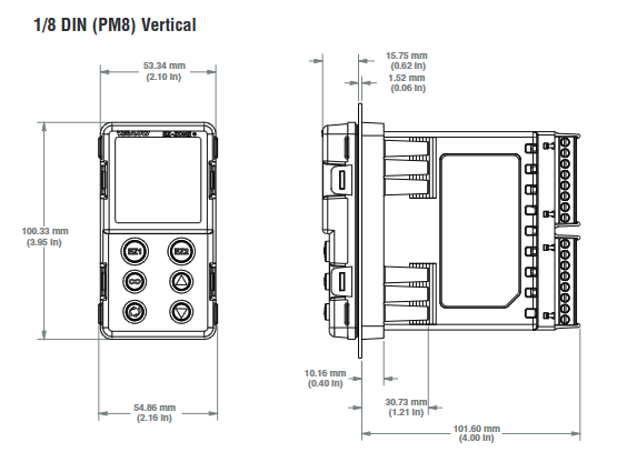
Process panel cutouts according to the size requirements of the corresponding model (1/32 DIN to 1/4 DIN), ensuring that the installation space meets the recommended spacing (such as the recommended panel spacing of 44.96-45.60mm for 1/8 DIN vertical type).
The panel thickness should be between 1.53-9.52mm to ensure a stable installation of the controller.
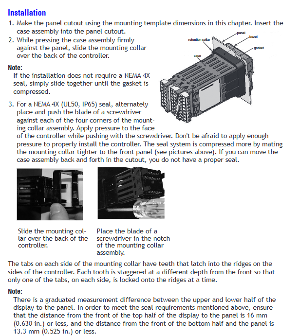
When installing, press the controller housing, slide the installation ring and tighten it. If NEMA 4X sealing effect is required, press the four corners of the installation ring alternately until it cannot shake.
(2) Wiring specifications
Before wiring, all power sources must be disconnected to avoid the risk of electric shock and follow NEC or local electrical standards.
Terminal wiring specifications: single wire 0.0507-3.30mm ² (12-30 AWG), or two 1.31mm ² (16 AWG) wires, with a tightening torque of 0.56 Nm (5.0 in lb).
Core terminal function:
Analog input terminal (Slot A): Supports thermocouples RTD、 Potentiometers and other inputs need to be wired correctly according to the type of sensor (such as the negative terminal of a thermocouple usually connected to the S1 terminal).
Power terminal (Slot C): Pin 98 is connected to the positive pole of AC/DC, and Pin 99 is connected to the negative pole of AC/DC.
Communication terminal: EIA-485 communication requires connecting T -/R - to terminal A and T+/R+to terminal B, using a daisy chain connection method, supporting up to 16 controllers in a network, with a maximum distance of 1200 meters.
(3) Environmental compatibility
Applicable media: acids, weak bases, alcohol, gamma rays, ultraviolet rays.
Avoid contact with strong alkalis, organic solvents, fuels, aromatic hydrocarbons, chlorinated hydrocarbons, etc.
Operation interface and navigation
(1) Key function
Key function
Adjust parameter values and switch menu options using the up/down keys; Long press for 3 seconds to enter the operation page, long press for 6 seconds to enter the settings page
Press the forward button (‰) to enter the submenu and confirm the selection; Long press for 6 seconds to enter the configuration file page
Infinite key (ˆ) returns to the previous menu; Long press for 2 seconds to return to the homepage; Clear Clearable Alarm/Error
(2) Core page navigation
Home: Default page for device power on, displaying process values (PV) and set values (SP), which can be directly adjusted.
Operation page: Press and hold the up/down keys for 3 seconds to enter, used for real-time monitoring (such as thermal power, cooling power) and temporary parameter adjustment (such as PID parameters, alarm status).
Settings page: Press and hold the up/down keys for 6 seconds to enter, used for basic configuration (such as sensor type, output mode, communication protocol).
Configuration file page: Long press the forward button for 6 seconds to enter, used for editing the slope insulation program (up to 4 files, 40 steps).
Factory page: Press and hold the forward key+infinite key for 6 seconds to enter, used for advanced functions such as calibration, password locking, and customizing the homepage.
Core functional configuration
(1) Input configuration (Settings page - Analog Input menu)
Sensor type (sEn): Select thermocouple (such as J-type), RTD (100 Ω/1k Ω), potentiometer, etc.
Range setting (r. Lo/r. hi): defines the measurement range of the input signal, such as 0-100 ° C.
Filter time (fiL): 0.0-60.0 seconds, used to smooth the input signal and reduce interference.
(2) PID control configuration
Control mode (C. ∧Џ): Supports automatic (closed-loop) and manual (open-loop) modes.
PID parameter adjustment:
Proportional band (h.pb/C.pb): 25.0 ° F (default), the smaller the value, the more sensitive the control.
Integral time (ti): 180 seconds/time (default), eliminating static errors.
Differential time (td): 0 seconds (default), suppresses overshoot.
Self tuning function (aUt): After activation, the controller automatically optimizes PID parameters, suitable for initial configuration or changes in operating conditions.
(3) Alarm configuration (Settings page - Alarm menu)
Alarm type (a.ty): Process alarm (triggered by fixed value) or deviation alarm (relative to set value).
Alarm threshold (a.Lo/a.hi): Set the trigger value for high and low alarms, such as a high temperature alarm of 300 ° F.
Alarm action (a.Lg): When an alarm occurs, output Energize (engaged) or De energize (disconnected).
Auxiliary functions: Supports locking (a. La), muting (a. Si), blocking (a. bL), etc., to avoid false alarms.
(4) Configuration file (slope insulation)
Step types: including heating (ti), insulation (SoAH), waiting for events (Ø І. E), jump (JL), etc.
Editing process: Enter the configuration file page, select the step type, and set parameters such as target temperature, time, and event output.
Startup method: The configuration file can be launched through the homepage, operation page, function keys, or numerical input.
Maintenance and troubleshooting
(1) Daily maintenance
Regularly check the tightness of the wiring to avoid looseness caused by vibration.
Sensor calibration: Use the calibration menu (CaL) on the factory page to input standard signals for offset and slope calibration.
Parameter backup: Save the parameters to User Set 1/2 through the Settings page Global menu (gLbL) for easy recovery after a failure.
(2) Common fault handling
Possible causes and solutions for fault indication
No display, power supply not connected, fuse blown. Check the power supply and replace the fuse
Alarm cannot be cleared. Alarm lock is activated, not restored to safe range. Release lock or wait for process value to return to threshold
No output action output function setting error, wiring error check output function configuration, rewiring
Process value deviates from set value, PID parameters are not optimized, sensor failure executes self-tuning, sensor inspection
Communication failure protocol mismatch, wiring error Unified communication protocol (such as Modbus RTU), check wiring
- OMRON
- ABB
- General Electric
- EMERSON
- Honeywell
- HIMA
- ALSTOM
- Rolls-Royce
- MOTOROLA
- Rockwell
- Siemens
- Woodward
- YOKOGAWA
- FOXBORO
- KOLLMORGEN
- MOOG
- KB
- YAMAHA
- BENDER
- TEKTRONIX
- Westinghouse
- AMAT
- AB
- XYCOM
- Yaskawa
- B&R
- Schneider
- KONGSBERG
- NI
- WATLOW
- ProSoft
- SEW
- ADVANCED
- Reliance
- TRICONEX
- METSO
- MAN
- Advantest
- STUDER
- DANAHER MOTION
- Bently
- Galil
- EATON
- MOLEX
- DEIF
- B&W
- ZYGO
- Aerotech
- DANFOSS
- Beijer
- Moxa
- Rexroth
- Johnson
- WAGO
- TOSHIBA
- BMCM
- SMC
- HITACHI
- HIRSCHMANN
- Application field
- XP POWER
- CTI
- TRICON
- STOBER
- Thinklogical
- Horner Automation
- Meggitt
- Fanuc
- Baldor
- SHINKAWA
- Other Brands
- UniOP
- KUKA
- Iba
- Beckhoff
-
 Basler DECS-100-B15 Digital AVR
 -
 Basler 9284900103 PS DECS-400N
 -
 Basler D4N3H1U Intertie Protection
 -
 Basler DECS-100-B15 A15 AVR
 -
 Basler KR4F Voltage Regulator
 -
 Basler BE26434 T14 Transformer
 -
 Basler SR8A-2B15B3A Regulator
 -
 Westinghouse 774B472A12 AR Relay
 -
Basler DECS-100-B15 AVR
-
 Basler XR2002F Regulator 110V
 -
 Basler SR125-E Static Regulator
 -
 Basler SSR 125-12 Regulator
 -
 Basler MOC2599 Motor Pot
 -
 Basler BE1-DFPR Feeder Relay
 -
 Basler CBS 305 Current Boost
 -
 Basler BE1-25 AutoSync
 -
 Basler MVC 300 Voltage Control
 -
 Basler BE3-25A AutoSync
 -
 Basler KR7FF Static Regulator
 -
 Basler 90-49000-100 Regulator
 -
 Basler 880 kVA Dry Type Transformer Specs
 -
 Basler Electric BE1-25 Sync-Check Relay Specs
 -
 Basler SSR 125-12 Voltage Regulator Specs
 -
 Basler Electric BE1-851 Overcurrent Relay Review
 -
Basler Electric 149D930G02 Control Sub-Assembly
-
 Basler Electric BE1-81O/UT Frequency Relay Specs
 -
 Basler Electric BE1-51/27C Overcurrent Relay
 -
 Basler Electric 149D956G02 Industrial Component
 -
Basler Electric BE1-51A Overcurrent Relay Specs
-
 Basler Electric BE1-40Q Loss of Excitation Relay
 -
 Basler DECS-200 Excitation Control System
 -
 Basler DECS-200 Voltage Regulator 56-277V AC / 125V DC
 -
 Basler BE1-87T Transformer Differential Relay
 -
 Basler RDP-110-S1 Protection Relay
 -
 Basler BE1-700V Digital Protective Relay
 -
 Basler BE1-951 Overcurrent Protection System
 -
 Basler DECS-300 Digital Excitation Control
 -
 Basler DECS-200 Digital Excitation Control
 -
 Basler DECS-200-1C Excitation Control System
 -
Basler DECS-200-1L Digital Excitation Control
-
 Basler Electric BE1-GPS Generator Protection System
 -
Basler Electric DECS-200-1C Digital Excitation Controller
-
 Basler Electric DECS125-15 Excitation Control with Power Module
 -
 Basler Electric BE1-87G Differential Relay
 -
 Basler Electric BE1-11 Protection System I5A3M2P2N0EA00
 -
Basler Electric DECS-200-1C Excitation Control System
-
Basler Electric BE1-11g Generator Protection Relay
-
 Basler Electric DECS 125-15-B2C1 V2.0.9 Excitation Control
 -
 Basler Electric BE1-81O/UT3ED1JA7N2F Frequency Relay
 -
Basler Electric BE1-81O/UT3EE1YB7N1F Frequency Relay
-
 Basler Electric DECS-200-1L Digital Excitation Control System
 -
Basler DECS125-15-B2C1 Excitation Control
-
 Basler 9507900205 SSR Retrofit Voltage Regulator
 -
 Basler BE2000E Digital Voltage Regulator
 -
 Basler BE1-GPS Generator Protection System
 -
Basler DECS-250-CN1CN1N Digital Excitation Control
-
 Basler DGC-2020 Genset Controller
 -
 Basler BE1-81O UT3ED1LA7N0F Frequency Relay (Variant)
 -
 Basler BE1-81O UT3EE1YA9S0F Frequency Relay (Variant)
 -
Basler BE1-81O Over/Under Frequency Relay
-
Basler DECS125-15 Digital Excitation Control
-
Basler Electric BE1-951 Overcurrent Protection System
-
 Basler Electric BE1-700V Digital Protective Relay
 -
 Basler Electric APR63-5 Automatic Voltage Regulator
 -
Basler Electric BE1-851 Overcurrent Protection System
-
Basler Electric DECS-250-LN1SN1N Excitation Control
-
 Basler Electric BE1-87T Transformer Differential Relay
 -
Basler Electric DECS-200-1L Excitation Control System
-
 Basler Electric 9310300100 DECS-300 Excitation Control
 -
 Basler Electric SSE-N 125-4.5KW Shunt Exciter Regulator
 -
 Basler Electric DGC-2020HD-5NS1DNSBA Genset Controller
 -
Basler Electric BE1-81-O/UT3EE1JB7N1F Frequency Relay
-
Basler Electric BE1-81T1EE1WA0N1F Frequency Relay
-
 Basler Electric BE1-25M1EA6PN5R1F Sync-Check Relay
 -
 Basler Electric BE1-GPS Generator Protection System
 -
Basler Electric DECS-250-LN1SN1N Excitation Control Rev V
-
 Basler Electric DECS-250-CN2CN1N Excitation Control
 -
Basler Electric BE1-50/51B-207 Overcurrent Relay
-
Basler Electric DECS-300-C0N0 Excitation Control System
-
Basler Electric DECS-200 Digital Excitation Control System
-
Basler Electric DECS-250-LN1CN1N Excitation Unit
-
Basler Electric DECS-250 LN2SA1D Excitation Unit Specs
-
Basler Electric BE1-87T Transformer Relay Review
-
Basler Electric BE1-11 Protection System
-
Basler Electric BE1-GPS100-E4N1H1N Protection System
-
 Allen-Bradley 442G-MABH-R Safety Module
 -
 Beckhoff CX1030-0111 PLC Assembly Profile
 -
 FANUC IC693CPU364 PLC Module
 -
 Orange Denmark Type 200816 220 PLC Specs
 -
 OMRON C200H-SNT31 Sysmac PLC Module
 -
 Allen Bradley 20AB022A3AYNANC0 PowerFlex 70
 -
 OMRON C200HW-PCU01 Position Control Unit
 -
 ABB AO845A-eA Analog Output Module
 -
 OMRON CJ1M-CPU22 CPU Unit
 -
 Allen Bradley 100-E265ED11 Contactor
 -
 Honeywell 51304511-100 Interface Module
 -
 SOLEXY BXF3S0101N0018 Gateway Module
 -
 OMRON CJ2H-CPU65 CPU Unit
 -
 Automation Direct GS2-45P0 AC Drive
 -
 M68-2000 2-Axis Motion CNC Controller
 -
 OMRON CJ1M-CPU11 V3.0 PLC CPU Unit
 -
 OMRON CJ1W-NC413 4-Axis Positioning Controller
 -
 OMRON 3G2A3-PRO16 Programming Console HMI
 -
 Siemens 3VT8440-2AA04-2GA2 Molded Case Circuit Breaker
 -
 Siemens 3RT5045 Contactor Series
 -
 OMRON C200HS-CPU01-E SYSMAC PLC Controller
 -
 OMRON C500-NC103-E Positioning Control Unit
 -
 OMRON CJ1W-TC001 Temperature Control Unit
 -
 OMRON NJ301-1100 NJ-PA3001 PLC System EtherCAT
 -
 Pilz 773100 M1P Safety Relay Base Unit
 -
 Siemens SINUMERIK 840D SL NCU 720.3B with PLC 317-3 PN/DP
 -
 Siemens 6AV6618-7GD01-3AB0 HMI Panel
 -
 OMRON F150-C15E-3 Vision Mate Controller PLC Overview
 -
 Mitsubishi MELSEC A Series PLC System A63P A3ACPU A616AD A68RD3
 -
 M68-2000 2 Axis Motion Controller SCE SERVO CNC
 -
 OMRON FZ-S2M PLC Camera Vision System
 -
 VISOLUX SLVA-4K PLC Module from Elektronik GmbH
 -
 OMRON CJ1M-CPU23 V2.0 PLC CPU Unit
 -
 ABB AI86-16CHF PCB Card 5761751-9 B Specifications
 -
 Allen-Bradley 100-D140ZJ22L Contactor Overview
 -
 Merlin Gerin PB80 PLC Rack
 -
 WEIR WE203 Power Supply PLC
 -
 OMRON NX-TS3102 Temperature Input Unit
 -
 Siemens 6ES7146-6FF00-0AB0 I/O Module
 -
 Fanuc A16B-3300-0057 Circuit Board
 -
 OMRON CJ1W-IDP01 Input Module
 -
 Siemens 6FX2007-1AD13 Handheld Unit
 -
 Gems EM54 PLC Module PCB


