
Emerson A6110 Dual Channel Shaft Vibration Monitor
signal conditioning
Measurement input: Channel 1 is z8: SENS1H (+), z10: SENS1L (- signal); Channel 2 is d8: SENS2H (+), d10: SENS2L (- signal). Input nominal range -1.0... -22.16V, limit range 0... -30V DC, input resistance>100k Ω, with differential voltage amplification input, no response, resistant to open and short circuits.
Sensor signal output: front panel SMB socket and/or z14/z16 * (depending on J2 jumper settings), channel 1 is SENS 1 SMB K1, and channel 2 is SENS 2 SMB K2. Signal output -1... -24V, 1:1 with sensor input signal, accuracy ± 1% of full scale, frequency range 0... 16kHz (-3dB) ± 20%, allowable load resistance>100k Ω, internal resistance 1k Ω, resistance to open and short circuits, no response.
Dynamic output: Channel 1 is AC1, channel 2 is AC2, corresponding to z14/z16 * (depending on the J2 jumper setting). The nominal range is 0... 20Vpp, the measurement range is consistent with the measurement range of the characteristic value configuration (minimum 400mVpp, maximum 8000mVpp), the accuracy is ± 1% of the full range, the frequency range is 0.1Hz... 16kHz (-3dB) ± 20%, the allowable load resistance is>10k Ω, the source impedance is 10k Ω, the internal resistance is about 20 Ω, it is resistant to open and short circuits, and has no response.
Scaling DC output: Channel 1 is NGL1, channel 2 is NGL2, corresponding to z12/d12. The nominal range is 0...+10V DC, the measurement range is consistent with the working range of the sensor configuration (0V corresponds to the lower limit of the working range,+10V corresponds to the upper limit of the working range), the accuracy is ± 1% of the full range, the resolution is 12 bits, the allowable load resistance is>10k Ω, the internal resistance is about 50 Ω, it is resistant to open and short circuits, and there is no response.
Characteristic value signal adjustment: The input signal is adjusted by adjusting the amplifier, range dependent amplifier, high pass and low-pass before digitization. The range setting is determined by the configuration, with a minimum measurement range of 400mVpp and a maximum of 8000mVpp. The high pass filter is a second-order Butterworth filter with adjustable parameters (0.5Hz (-3dB) corresponds to a working frequency of 1Hz, 2Hz (-3dB) corresponds to a working frequency of 5Hz), with a tolerance of ± 20%; The low-pass filter is a 5th order Butterworth filter with a parameter range of 50Hz... 2000Hz and a step size of 0.01Hz.
Characteristic value formation: Depending on the configuration, S1 and S2 are separate characteristic values during dual channel operation, and 0-P or S-S evaluation can be selected; The maximum offset S max conforms to the characteristic value A of DIN 45670; the larger vibration amplitude S ppm conforms to the characteristic value B of DIN 45670 or the Max (X, Y) of API 670.
Current output characteristic values: Current output 1 is I1+/I1- corresponding to z18/b18 (0V/common terminal), and current output 2 is I2+/I2- corresponding to z20/b20 (0V/common terminal). The nominal range is 0... 20mA or 4... 20mA (depending on the configuration). When operating at 4... 20mA, the output for fault detection can be set to 0mA (Life zero operation) through configuration settings. The accuracy is ± 1% of the full scale, the resolution is 16 bits, and the load resistance is allowed to be 500 Ω.
Signal output EO 1/EO 2: corresponds to d14/d16, voltage output 0... 10V. Corresponding to characteristic values in independent channel mode, outputs single channel measurement values in S max and S PPmax modes, measurement range and evaluation corresponding characteristic values, can be used for linking or display, resistant to open and short circuits, no response. The nominal range is 0...+10V DC, with a resolution of 8 bits, allowing a load resistance of>10k Ω and an internal resistance of approximately 50 Ω.
Signal input EI1/EI2: Used to connect single channel measurement values 1...+10V for EO output, corresponding to b14/b16. The nominal voltage range is 0...+10V DC, with a resolution of 10 bits and an input resistance of>100k Ω.
Signal input KEY: used for internal speed determination to check the measurement in the analysis of measurement values, corresponding to d22. The signal level is 24V logic (LOW=0... 3V; HIGH=13... 48V), and the input resistance is>10k Ω.
Channel monitoring
Monitoring function: Continuously monitor sensor signals (within the configuration related GOOD range), system voltage (voltage OK), microprocessor functions (watchdog, WD-OK), configuration and setting parameters (C&P-OK), external disable signals (ES).
GOOD threshold: The lower limit is the lower limit of the sensor's working range -0.5V, and the upper limit is the upper limit of the sensor's working range+0.5V.
Channel status: No errors (OK) must meet the requirements of voltage OK, WD OK, C&P OK, sensor signal within the GOOD range, and no external disabling; If not satisfied, it is in an error state; When switching from an error state to an OK state or when the module is turned on, a release delay of 15 seconds (± 2 seconds) is considered as the release delay state.
- ABB
- General Electric
- EMERSON
- Honeywell
- HIMA
- ALSTOM
- Rolls-Royce
- MOTOROLA
- Rockwell
- Siemens
- Woodward
- YOKOGAWA
- FOXBORO
- KOLLMORGEN
- MOOG
- KB
- YAMAHA
- BENDER
- TEKTRONIX
- Westinghouse
- AMAT
- AB
- XYCOM
- Yaskawa
- B&R
- Schneider
- Kongsberg
- NI
- WATLOW
- ProSoft
- SEW
- ADVANCED
- Reliance
- TRICONEX
- METSO
- MAN
- Advantest
- STUDER
- KONGSBERG
- DANAHER MOTION
- Bently
- Galil
- EATON
- MOLEX
- DEIF
- B&W
- ZYGO
- Aerotech
- DANFOSS
- Beijer
- Moxa
- Rexroth
- Johnson
- WAGO
- TOSHIBA
- BMCM
- SMC
- HITACHI
- HIRSCHMANN
- Application field
- XP POWER
- CTI
- TRICON
- STOBER
- Thinklogical
- Horner Automation
- Meggitt
- Fanuc
- Baldor
- SHINKAWA
- Other Brands
- UniOP
- KUKA
- Iba
-
 OMRON CJ1W-PTS52 Temperature Unit
 -
 Sacs Technique PCD4.M12 Module
 -
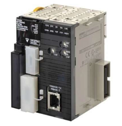 OMRON CJ1M-CPU11-ETN Ethernet CPU
 -
 OMRON CJ1M-CPU23 PLC CPU Unit
 -
 OMRON NX-SID800 Safety Input Unit
 -
 GE Fanuc Series 90-30 PLC
 -
 OMRON CJ1W-NCF71 Position Control
 -
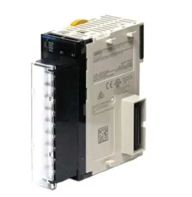 OMRON CJ1W-AD081-V1 Analog Input
 -
 OMRON FZ-S2M Vision Camera
 -
 OMRON R88D-UEP20V Servo Driver
 -
 OMRON F500-C10-ETN Vision Controller
 -
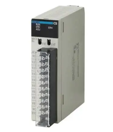 OMRON CS1W-DA041 Analog Output Module
 -
 PRO-FACE GP577R-TC41-24VP HMI Panel
 -
 TRUTZSCHLER RAK 1 492-58.430.000 PLC Module
 -
 OMRON NX-OD5256 Output Module
 -
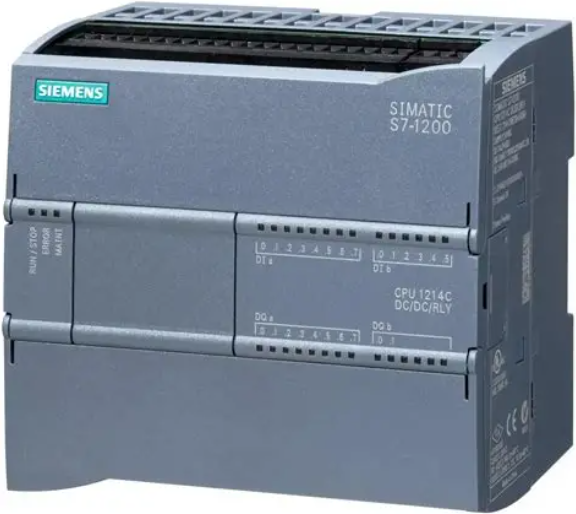 Siemens 6AG1214-1AG40-4XB0 PLC
 -
 OMRON CJ1W-AD081-V1 Analog Unit
 -
 OMRON C500-CPU11-E PLC CPU
 -
 OMRON NX-ECC201 EtherCAT Coupler
 -
 OMRON F300-A20S Camera Interface
 -
 Mitsubishi 80173-109-01 PLC Module
 -
 Fanuc A16B-2200-0141 PCB Board
 -
 Lenze EPL10200 PLC Module
 -
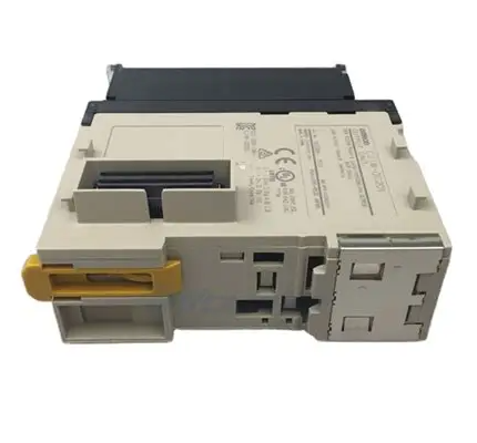
 OMRON CJ1M-CPU13 PLC CPU Unit
 -
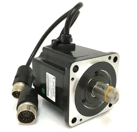
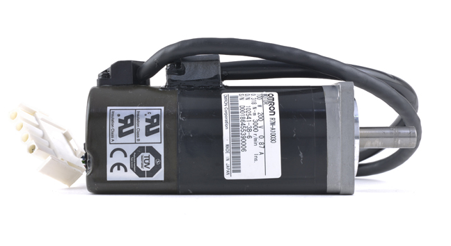
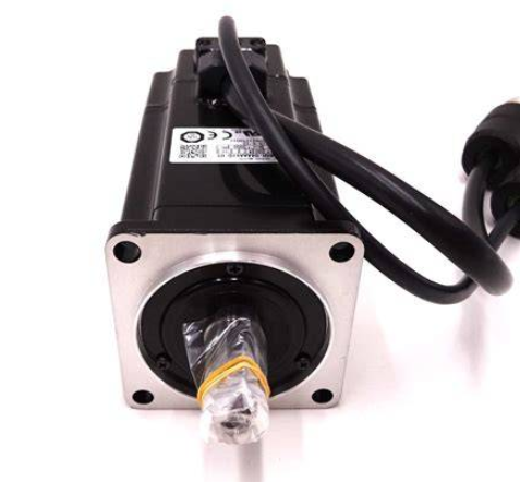 Yaskawa SGMPH-04AAA61D-OY Motor
 -
 OMRON NX-SOD400 Safety Output
 -
 Control Techniques V1800 Flux Vector Drive
 -
 Yaskawa SGDH-04AE-OY Servo Drive
 -
 OMRON NT-DRT21 DeviceNet Interface
 -
 OMRON C500-RM001-V1 Remote I/O Master
 -
 OMRON C500-AD006 Analog Input Module
 -
 OMRON 3G3MV-A4055 Inverter Drive
 -
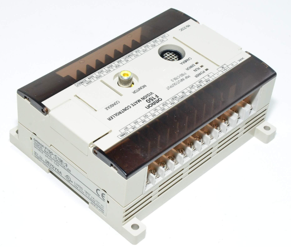 OMRON F150-C15E-3 Vision Mate Controller
 -
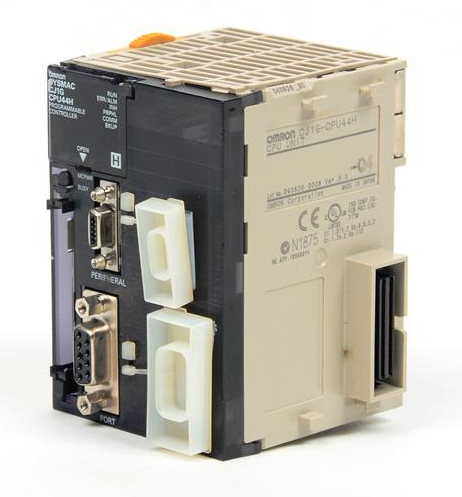
 OMRON CS1G-CPU44H PLC CPU
 -
 GE Fanuc DS6800CCIE1E1D CPU Module
 -
 Omron CP1L-M30DR-A PLC CP1W-CIF01 CPU Unit
 -
 Heraeus 585923 2M130 M8 Electrode Assembly Sensor
 -
 Omron C40P-EDT1-D C Series PLC Controller
 -
 Yaskawa SGMGH-09DCA6F-OY Servo Motor SGDH Driver
 -
 Datalogic SG-BWS-T4-MT Safety Control Unit Category 4
 -
 Pro-face PFXLM4301TADDC HMI Controller LT-4301M
 -
 Mitsubishi FX1N-60MR-DS PLC Main Unit 60 I/O
 -
 Omron NJ501-1320 Sysmac Database Connection CPU
 -
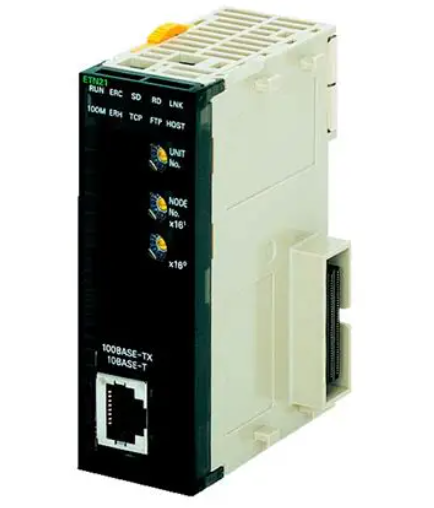
 Omron CJ1W-ETN21 Ethernet Unit CJ Series Module
 -
 Siemens 6ES7517-3AP00-0AB0 CPU 1517-3 PN/DP
 -
 Pasaban MTC-3052 Fast I/O PLC Module
 -
 Mitsubishi FX3U-128MR/ES-A PLC
 -
 OMRON CS1W-CLK21 Controller Link Unit
 -
 Yokogawa ADV151-E63 Digital Input Module
 -
 Allen Bradley MPL-B680B-M-X227 Motor
 -
 OMRON CJ1W-NC413 4-Axis Position Unit
 -
 Yaskawa SGMGH-30DCA6H-OY Servo Motor
 -
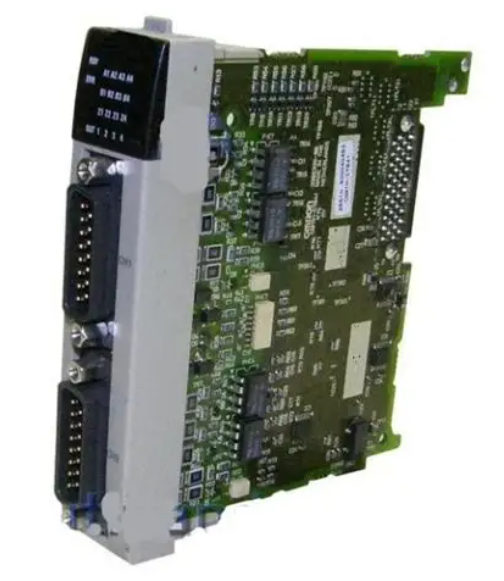
 Bosch 1070075337-101 Output Card
 -
 OMRON CQM1-CPU45-EV1 PLC CPU Unit
 -
 Siemens 6SE7090-0XX84-0AG1 CU3 Control Module
 -
 OMRON CQM1-TC101 Temperature Control Module
 -
 MOOG OEM-1030-422 Wind Energy PLC Controller
 -
 OMRON ZFX-C15 Vision Sensor
 -
 Square D 8702SCO2V02 Reversing Contactor
 -
 OMRON C20-LK201-EV1 PLC Link Adapter
 -
 OMRON NB7W-TW01B HMI PLC
 -
 Siemens 7ME6920-1AA10-1AA0 Flow Transmitter
 -
 Allen Bradley 1791-8BR Block I/O Module
 -
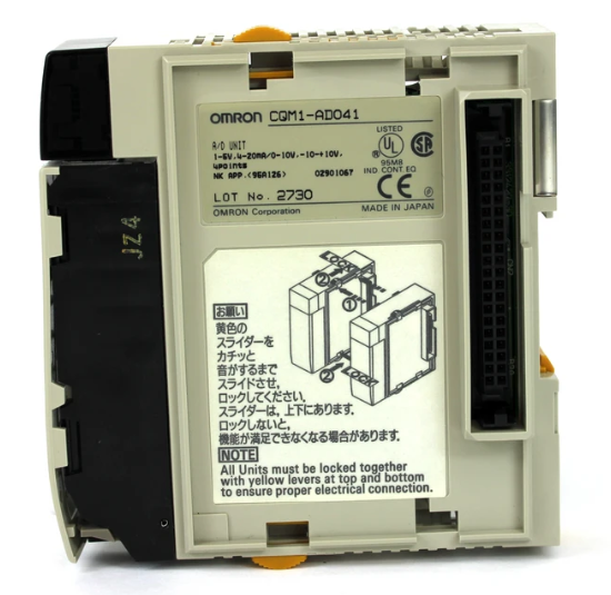
 OMRON CQM1-AD041 Analog Input Module
 -
 OMRON CJ1M-CPU21 PLC Module
 -
 Omron Z500-MC10E-001 Laser Profile Controller
 -
 Omron NA5-7W001B-V1 NA Series Programmable Terminal HMI
 -
 Allen-Bradley 1606-XLS960EE Power Supply 960W 24VDC
 -
 GE DS3800NEPB1F1E Power Excitation Board Mark IV
 -
 Yaskawa SGDH-04AE-OY Sigma-II Servo Drive 400W
 -
 Allen-Bradley 2711P-RBT7 PanelView Plus 7 Bezel
 -
 CCS PD3-3024-3-EI Digital Control Unit 3 Channel
 -
 Yaskawa CPU301 MP3300 Controller JAPMC-CP3301-2-E
 -
 Omron C40P-EDR-D PLC C Series P Type Controller
 -
 Omron NX-SID800 Safety Input Unit 8 PNP 24VDC
 -
 ABB SCC-C 23070-0-10232110 gas cooler
 -
 Sick LGTN101-521 CPU Module
 -
 Okuma 1911-2836 PLC Circuit Board
 -
 Mitsubishi Melsec PM-120M PLC
 -
 Omron F210-C15 Vision Mate Controller System
 -
 Siemens 7ML5110-1GD07-4AF3 Ultrasonic Level Gauge
 -
 ABB Pluto S46 V2 Safety Relay
 -
 Omron Z3RN-5A Optical Serial Link
 -
 Omron R7D-APA3H 30W Servo Drive
 -
 Giddings Lewis 502-03638-41R3 PLC Processor
 -
 Omron SCY-P1 Sequencer Controller
 -
 Siemens C98043-A7002-L1-13 PCB Board
 -
 SACS TECNICA Palletizer PC PLC Control System
 -
 AutomationDirect T1F-14THM PLC Module T1F14THM
 -
 OMRON C200H-AD003 Analog Input Unit PLC Module
 -
 Applied Materials 0010-A0000 Electricity Box PLC 200mm
 -
 ABB RVT-6 Power Factor Controller RVT6
 -
 Allen-Bradley 2094-BC01-MP5-M Kinetix 6000 Axis Module
 -
 OMRON FQM1S-MC233 Motion Controller PLC Module
 -
 OMRON C200H-SNT31 PLC Special I-O Module
 -
 Yaskawa SGMPH-04AAA61D-OY Servo Motor 400W 200V
 -
 Yaskawa SGMGH-09DCA6F-OY AC Servo Motor 850W 400V
 -
 REFU ELEKTRONIK SR17002 PLC Logic Module Circuit Board
 -
 Siemens 6DP1231-7AA PLC Board Module Industrial Control
 -
 ABB SACE ISOMAX S3 N 160 Molded Case Circuit Breaker
 -
 OMRON C120-SC024-V1 SYSMAC C120 Compact PLC Unit
 -
 OMRON CJ1W-SCU41-V1 Serial Communication Unit PLC Module
 -
 OMRON 3G3MX2-A4110-ZV1 MX2 Variable Frequency Drive
 -
 Yaskawa SGDH-04AE-OY Sigma-II Servo Driver 400W 200V
 -
 OMRON CQM1-AD041 Analog Input Module PLC I/O Unit
 -
 Delta Omega XML2-0060-45-4/S-A Servo Drive
 -
 Omron CJ1W-AD041 Analog Input
 -
 Omron CJ1W-NC271 Position Control Unit
 -
 Omron CJ1G-CPU45H PLC CPU
 -
 Omron CJ1W-EIP21 EtherNet/IP Unit
 -
 Omron F210-C15 Vision Mate Controller
 -
 Omron CQM1H-ADB21 Analog I/O Board
 -
 Omron GRT1-PRT PROFIBUS DP-V1 Adapter
 -
 Omron CP1H-Y20DT-D PLC CPU
 -
 TE.CO TFX 4G 1.5 Grey Cable 470m
 -
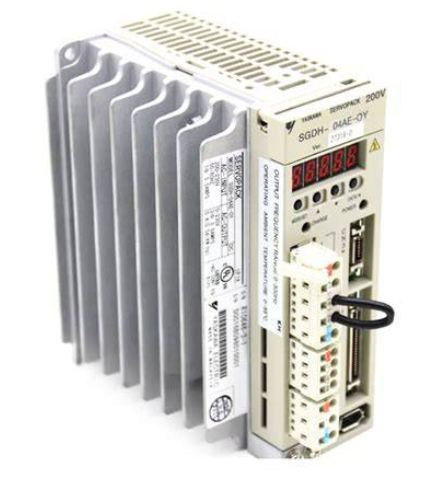 Yaskawa SGDH-04AE-OY Servo Driver 400W 200V
 -
 OMRON CJ1H-CPU66H V4.0 PLC CPU
 -
 OMRON R7M-A10030-BS1 Servo Motor 200W 100V
 -
 OMRON FQM1-MMA21 Motion Controller
 -
 Yaskawa SJDE-08APA Servo Amplifier
 -
 OMRON CQM1-AD041 Analog Input Unit
 -
 Siemens OCI55 Dialogue Module Landis
 -
 OMRON F350-C10E Image Processing Unit
 -
 OMRON NT10S-SF121 HMI Terminal
 -
 SIEMENS 3RB1262-0LB31 Overload Relay
 -
 OMRON YASKAWA SGDS-02A12A Servo Drive
 -
 TE.CO TFX 4G 1.5 Grey Cable ST 500m
 -
 FANUC A16B-3200-0362 PCB Control Board


