
Emerson A6110 Dual Channel Shaft Vibration Monitor
Emerson A6110 Dual Channel Shaft Vibration Monitor
Basic Overview
The A6110 dual channel shaft vibration monitor is a module of the A6000 machine monitoring system, controlled by a microprocessor and used in conjunction with two eddy current measurement chains to measure and monitor the relative shaft vibration of various turbines, compressors, fans, gearboxes, and other equipment. Its two channels can be configured to be used as independent channels or interrelated, with multiple operating modes, and characteristic values can be output through the 0/4... 20mA current of each channel.
CSA Certification
Certification Mark: According to CSA certification requirements, all devices (IMR 6000/xx and A6000 modules) must be labeled with the corresponding CSA label, otherwise the device has not obtained CSA certification.
Acceptance Criteria
Power supply: 24V safe low voltage SELV LPS (C22.2 60950-1) is required for power supply, and the voltage must come from an independent power source.
Installation environment: The IMR system should be placed in a suitable fire-resistant enclosure; The working environment temperature of the system is between 0 ° C and 45 ° C; at least 1 RU (13/4 inches) of ventilation space needs to be provided to prevent heat accumulation. If the ambient temperature of the rack exceeds 45 ° C, equipment such as forced fans and coolers should be used to cool the instrument.
Multi unit installation: When multiple IMR units are installed vertically in a cabinet, a cooling fan bracket needs to be installed in the middle instead of reserving ventilation space. The specific specifications of the cooling fan bracket need to be determined according to the environment and location conditions of the cabinet.
Installation and assembly
Installation requirements: According to the IEC 61010 directive, fixed installation systems must be equipped with power disconnect devices (such as switches or circuit breakers that comply with IEC60947-1 and IEC60947-3). When using an IMR rack, such switches or circuit breakers must be installed in the cabinet, easy for users to operate, and labeled according to the relevant system.
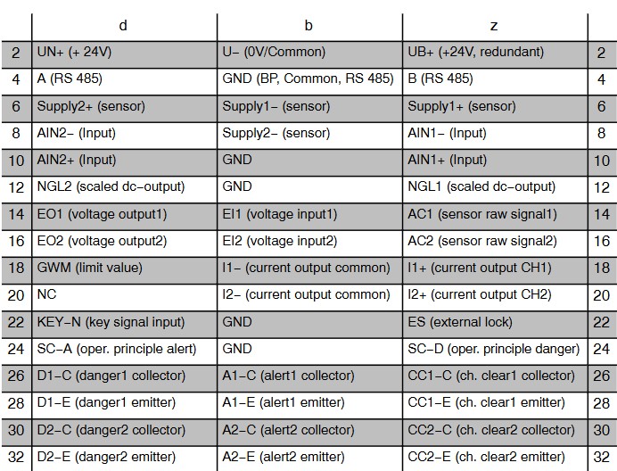
Installation preparation: Installing the A6110 monitor requires a pre prepared 3U slot or other Intermas compatible enclosure in a 19 inch rack, and the slot must be equipped with a 48 pin plug connector (DIN 41612, design F 48 M).
Pin allocation: Detailed pin allocation information is shown in the table below (some key pins):
Pin Position Function Description
2 UN+(+24V), U - (0V/common terminal), UB+(+24V, redundant)
4 A (RS 485), GND (BP, common terminal, RS 485)、B(RS 485)
6 Supply2+(sensor), Supply1 − (sensor), Supply1+(sensor)
8 AIN2- (input), Supply2- (sensor), AIN1- (input)
10 AIN2+(input), GND, AIN1+(input)
18 GWM (limit), I1- (current output common terminal), I1+(channel 1 current output)
20 NC, I2- (current output common terminal), I2+(channel 2 current output)
Jumper settings
RS 485 jumper: When the RS 485 bus is running, the first and last bus devices require electrical terminators, which are implemented through plug-in jumpers on the controller board. Jumper 1-2 is closed: Bus "B" is grounded through a pull-down resistor; Close jumper 3-4: Connect a 120 Ω resistor between "A" and "B"; Jumper 5-6 closed: Bus "A" is connected to+5V through a pull-up resistor. In the delivery state, the jumper is in the open state (bus terminator disabled, reference terminal open circuit). To ensure the fault free operation of the RS 485 bus, the "A" and "B" lines must be connected to their reference terminals (+5V, ground) in one monitor, and the bus terminator jumper of that monitor must be closed.
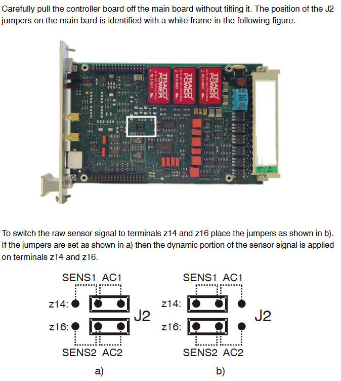
Sensor raw signal jumper: The sensor raw signal (unfiltered in-phase output signal, including AC and DC parts) on the front panel SMB socket can be switched to the z14 (channel 1) and z16 (channel 2) terminals of the connecting strip through J2 jumper. The switching steps are as follows: Use a Phillips screwdriver to remove the four screws, carefully remove the controller board, set the J2 jumper as required (a status is dynamic signal, b status is original signal), reinstall the controller board and tighten the screws. The reference point for the original sensor signal of channel 1 is the connecting strip terminal z6: SENS1+, and channel 2 is d6: SENS2+. If these terminals are connected to the b10 terminal, the reference point is the system ground (GND). At this time, b22: GND and b24: GND can also be used as reference points. During operation, attention should be paid to preventing electrostatic discharge, such as wearing an ESD wristband.
Monitor installation: Before installation, check the slot wiring, push the A6110 monitor into the prepared slot, gently press it to insert it into the plug connector, and then gently tighten the two fixing screws on the front panel by hand. For more information on shielding and grounding, monitor configuration, etc., please refer to the instructions for using the "Shaft Vibration Monitor A6110" (order number 6100-90001).
Technical Specifications
- OMRON
- ABB
- General Electric
- EMERSON
- Honeywell
- HIMA
- ALSTOM
- Rolls-Royce
- MOTOROLA
- Rockwell
- Siemens
- Woodward
- YOKOGAWA
- FOXBORO
- KOLLMORGEN
- MOOG
- KB
- YAMAHA
- BENDER
- TEKTRONIX
- Westinghouse
- AMAT
- AB
- XYCOM
- Yaskawa
- B&R
- Schneider
- KONGSBERG
- NI
- WATLOW
- ProSoft
- SEW
- ADVANCED
- Reliance
- TRICONEX
- METSO
- MAN
- Advantest
- STUDER
- DANAHER MOTION
- Bently
- Galil
- EATON
- MOLEX
- DEIF
- B&W
- ZYGO
- Aerotech
- DANFOSS
- Beijer
- Moxa
- Rexroth
- Johnson
- WAGO
- TOSHIBA
- BMCM
- SMC
- HITACHI
- HIRSCHMANN
- Application field
- XP POWER
- CTI
- TRICON
- STOBER
- Thinklogical
- Horner Automation
- Meggitt
- Fanuc
- Baldor
- SHINKAWA
- Other Brands
- UniOP
- KUKA
- Iba
- Beckhoff
-
 OMRON B7AM-8B16 I/O Terminal Block
 -
 Fanuc A06B-6110-H026 Power Supply Module
 -
 Schneider TSXETG3021 Ethernet Gateway
 -
 OMRON CS1W-CLK21-V1 Controller Link Unit
 -
 NP1W6406T-Z704 PLC I/O Module
 -
 OMRON CJ1W-DA08C Analog Output Module
 -
 Yaskawa 3G3HV-A4022-CE AC Drive
 -
 OMRON NB7W-TW01B CP1L-EL20DR-D Power Panel
 -
 OMRON C500-NC103-E Position Control Unit
 -
 Steag Hamatech PLC DCS Servo Control System
 -
 Siemens 6SN1123-1AA00-0DA1 Power Supply Module
 -
 GE IC693CHS391H CPU & AD693CMM301A PLC Module
 -
 Siemens 6FC5303-0AF23-1AA1 PLC Control Panel
 -
 Square D CM4000T PowerLogic Circuit Monitor J1 F16
 -
 Siemens 6FX5002-5DG10-1BA0 MOTION-CONNECT 500 Cable
 -
 Schmersal SRB324ST 101195504 Safety Relay 24V
 -
 Mitsubishi 15050-PR02A PLC Circuit Board Module
 -
 OMRON CQM1-AD041 Analog Input PLC Module
 -
 Beckhoff EL5042 EtherCAT PLC Terminal Module
 -
 OMRON C200HW-MC402-E Motion Control Unit
 -
 C36TC0UA1100 Industrial Temperature Controller
 -
 NL8048BC24 12 Industrial Control LCD Module
 -
 OMRON R88D Servo Drive and Motor System
 -
 OMRON CS1W CLK21 V1 Controller Link Module
 -
 OMRON YASKAWA R7M A20030 S1 D Servo Motor
 -
 SIEMENS 6AV2128 3KB06 0AX1 Unified Comfort Panel
 -
 Schneider Electric METSEPM8240 PowerLogic Meter
 -
 Advanced AMCI 1PLC 1 31F Programmable Limit Switch
 -
 ABB PM582 ETH Programmable Logic Processor
 -
 SIEMENS 6FC5110 0CB01 0AA0 CPU Control Board
 -
 Schleicher P03GS13A CPU Module
 -
 Siemens 6SN1123-1AA00-0BA1 Power Module
 -
 Mitsubishi A1S61PN Power Supply Module
 -
 Yaskawa CPS-IONB DC Power Supply Module
 -
 Siemens 6ES7215-2BD00 CPU 215-2
 -
 Mitsubishi A2ACPU MELSEC PLC System Kit
 -
 ProSoft 3150-MCM Communication Module
 -
 Mitsubishi OSE104ET Incremental Encoder
 -
 OMRON CJ1W-AD081-V1 Analog Input Module
 -
 Broadcom BCM5464A1KRB Quad Port Ethernet IC
 -
 Modicon M221-24IO TM221C24 PLC 24 PNP Transistor
 -
 Allen-Bradley 1321-3R160-B Line Reactor 3R160B
 -
 Beckhoff CX1020-0012 Embedded PLC Module Specs
 -
 Turck BL20-PF-24VDC-D Power Feed Module Specs
 -
 Siemens 6SY7000-0AC37 Power Supply Module
 -
 Yaskawa SGDH-10DE-OY 1kW 400V Servo Drive Specs
 -
 Omron 3G3SV-BB015-E 1.5kW 220V VFD Specs
 -
 Uni-Pro CPU91-PLC J 23.020167X Processor Module
 -
 PASABAN MTC-3044 PLC Rack Power Supply 4835-A
 -
 XYCOM 3015T Operator Interface Panel BIN4.4.4
 -
 OMRON CJ1W-MD261 Mixed I/O Module
 -
 Omron NJ301-1100 PLC CPU eCat EIP Specs
 -
 Omron F500-C15-ETN Vision System PLC Module
 -
 Modicon M241-24IO TM/T2UK PLC with Ethernet
 -
 SIXNET YS-800-001 RTU PLC Module
 -
 BEMAC UST-202-D Interface Board 1307D V08B2
 -
 Yaskawa JANCD-MMOIC-02 Drive Circuit Board
 -
 ABB 3BSE005028R1 SDCS-COM-1 Comm Board
 -
 Omron 3G3MX2-A4110 A4150 Inverter Drives Specs
 -
 KEYENCE CA-E100 PLC Module
 -
 GE IC693ALG223-GB Analog Input Module Specs
 -
 ABB BAILEY IMMFP01 Multi Function Processor System
 -
 SIEMENS 6FC5372 0AA00 0AA1 NCU 7202 Controller
 -
Modicon TM241CE4 40I O Transistor Programmable Controller
-
 SIEMENS 6ES7 315 2EH13 0AB0 CPU 3152 PN DP
 -
 NORIS A1 91 PCB Card Rack Module System
 -
 SIEMENS 6ES7 313 5BE01 0AB0 Compact CPU
 -
 SCHNEIDER ELECTRIC S144B MICROLOGIC 60A Trip Unit
 -
 CNI PLC269 v3 Control Module Board Rev H
 -
ABB BAILEY IIMCP02 Processor Module
-
 OMRON NT20S ST121 EV3 Operator Interface Terminal
 -
 OMRON NS-CA001 Video Input Unit
 -
 GE Fanuc IC695CHS012 RX3i Backplane
 -
 Allen Bradley 2711E-K14C6 PanelView 1400e Terminal
 -
 Siemens Sinamics CCB 10000432.71 Power Cell
 -
 Siemens 6SL3210-1SE21-8UA0 Power Module PM340
 -
 Yaskawa CIMR-F7A20P4 AC Drive
 -
 Beckhoff EP1918-0002 EtherCAT Box I/O Module
 -
 OMRON CQM1-TC001 Temperature Control Module
 -
 GE Fanuc SGHA36AT0400 Industrial Contactor
 -
 OMRON NJ501-1500 PLC Machine Automation Controller
 -
 Mitsubishi MAZAK QX084 Power Supply MELDAS 500 CNC
 -
 B&R 0AC808.9 PLC Automation Module
 -
 OMRON CP1H-XA40DT1-D PLC Module
 -
 G&W Electric PLC15 5111 011 15kV Capnut Assembly
 -
 GE DS200SLCCG3AGH PCB Circuit Board
 -
 Siemens SINUMERIK 6FC3981-4FD PLC Extension
 -
 OMRON F300-DC I/O Image Processing Unit
 -
 FANUC A06B-0314-B002 AC Servo Motor
 -
 GC-S84 Programmable Controller Logic Module
 -
 PASABAN MONTELEC MTC3001-DC Drive Control PLC
 -
 Allen Bradley 100E460EJ11 Auxiliary Contactor
 -
 Bosch Rexroth 1070075337-101 Card Parameters
 -
 HMS Anybus AB7646-F Gateway Specifications
 -
 Bosch 062633-303401 CNC Servo PLC Card
 -
 TI 500-5023 Series PLC Power Supply
 -
 Siemens C98043-A7002-L1-12 Circuit Board
 -
 Omron E5CC-RX3A5M-000 Controller
 -
 CN-8032-L Profinet Network Adapter Module
 -
 Siemens 3TK2804-0BB4 Safety Relay Details
 -
 Toledo TTLM-2-1M I/O Load Module
 -
 NORIS A1-91 PLC Rack Board Specifications
 -
 Mitsubishi A3ACPUR21 MELSEC PLC CPU Module
 -
 Beckhoff EP7041‑3002 EtherCAT Box Digital Input Module
 -
 REER EOS2E 1053 EOS2R 1053 Safety Light Curtain
 -
 Mitsubishi Q80BD-J71BR11 MELSECNET/H Interface Board
 -
 Omron 3G3IV-B4220-EV2 VFD 400V 22kW
 -
 Allen-Bradley 96844671 1785-LT3 PLC-5/12 Processor Module
 -
 Pasaban MTC3001-DC Drive Control PLC Module
 -
 Omron CJ1M-CPU11 V4.0 PLC CPU Module
 -
 ABB CM579-PNIO B3 Communication Module
 -
 B&R X20 AI 4221 Analog Module
 -
 Siemens 6SY7000-0AC80 PLC Module
 -
 GE 531X300CCHAFM5 Control Card
 -
 AB 810-A15C Inverse Time Relay
 -
 WITTENSTEIN LP120X-MF2-20 Planetary Gear
 -
 Mitsubishi Kakoki E-01B-4130 PLC I/O Modules
 -
 ABB DSQC643 Safety Control Board
 -
 Siemens G26004-A2105-P100-2 PCB
 -
 OMRON F350-C10E Image Processing Unit
 -
 FUJI UG430H-TS1 HMI Touch Panel
 -
 Westronics CB100188-01 Rev F Board
 -
 Siemens 7MH4900-3AA01 Weighing Module
 -
 Gilbert & Nash Tracker 2000 Control Cabinet
 -
 OMRON CJ1M-CPU22 CPU Unit
 -
 OMRON F3SJ-E0625P25 Light Curtain
 -
 Siemens 3VA2340-5HL32-0AA0 Breaker
 -
 Mitsubishi Melsec A61P A2NCPU PLC System


