
Foxboro Evo ™ FBM242 Discrete Output Module
Foxboro Evo ™ FBM242 Discrete Output Module
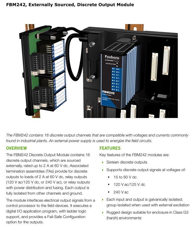
Module Core Overview
FBM242 is Schneider Electric Foxboro Evo ™ The external power supply discrete output module in the process automation system has 16 discrete output channels, which can adapt to common voltages and currents in industrial scenarios. It requires an external power supply to power the field circuit and can achieve electrical output signal interaction between the control processor and field devices. It supports digital I/O applications (including ladder logic) and provides output fault safety configuration options.
Key characteristics
Channel and voltage support: Includes 16 discrete output channels, compatible with various voltage signals including 15-60V DC, 120V AC/125V DC, and 240V AC.
Isolation protection: Each input and output adopts galvanic isolation (electrical isolation), and when combined with external excitation, it is group isolation, which can avoid interference between different channels and ground.
Environmental adaptability: Adopting a sturdy design, the shell is made of extruded aluminum, which can be installed in G3 level (harsh) environments that comply with ISA standard S71.04, and can withstand vibration (7.5m/s ², 5-500Hz).
Configurable functions: When executing discrete I/O or ladder logic programs, options such as input filtering time, fail safe configuration, fail safe fallback, and continuous/instantaneous output can be configured.
Visual indication: The front of the module is integrated with LED indicator lights, which can display the running status of the module and the discrete status of each output point, facilitating real-time monitoring.
Convenient maintenance: Modules can be disassembled and replaced without dismantling on-site equipment wiring, power or communication cables, reducing maintenance downtime.
Communication redundancy: Connected to the fieldbus communication module (FCM) or control processor (FCP) through a redundant 2Mbps fieldbus, the two communication paths (A/B) can automatically switch to ensure communication continuity.
Safety design: The on-site power supply of contacts or solid-state switches has current limiting protection to ensure the safety of equipment and personnel.
Detailed technical specifications
(1) Output channel parameters
Parameter values
Number of channels: 16 isolated channels
Maximum application voltage 15-60V DC
Load current single channel maximum 2.25A
At surge current of 30 ° C, the maximum current in a single channel within 20ms is 8A; at 70 ° C, the maximum current in a single channel within 20ms is 6.4A
Maximum 0.2V when the on state voltage drop is 2.25A
Maximum open state leakage current of 0.1mA
Inductive load protection requires connecting protective diodes or metal oxide varistors (MOVs) at both ends of the inductive load
Isolate and withstand voltage between any channel and ground, between any two channels, apply 600V AC voltage for 1 minute without damage (note: do not operate at this voltage for a long time, otherwise it violates safety regulations and poses a risk of electric shock)
(2) Power supply and power consumption
Input voltage range (redundant): 24V DC (± 5%/-10%)
Maximum power consumption: 3W at 24V DC
Maximum heat dissipation: 6.5W when 24V DC and all outputs are 1.5A
(3) Environmental specifications
Environmental Condition Module Terminal Component (PA)
Working temperature -20 to+70 ° C (-4 to+158 ° F) -20 to+70 ° C (-4 to+158 ° F)
Working humidity 5% -95% (non condensing) 5% -95% (non condensing)
Working altitude -300 to+3000m (-1000 to+10000ft) -300 to+3000m (-1000 to+10000ft)
Storage temperature -40 to+70 ° C (-40 to+158 ° F) -40 to+70 ° C (-40 to+158 ° F)
Storage humidity 5% -95% (non condensing) 5% -95% (non condensing)
Storage altitude -300 to+12000m (-1000 to+40000ft) -300 to+12000m (-1000 to+40000ft)
(4) Physical specifications
Installation method: The module is installed on a modular base plate, which can be DIN rail mounted (horizontal/vertical) or horizontally mounted on a 19 inch rack through an installation kit; The terminal assembly (TA) is installed on a DIN rail (compatible with 32mm and 35mm specifications).
Weight: The module weighs approximately 284g (10oz); The weight of terminal components varies depending on their specifications, with the 127mm model weighing approximately 272g (0.60lb), the 148mm model weighing approximately 285g (0.65lb), and the 216mm model weighing approximately 320g (0.70lb).
Module dimensions: height 102mm (4in, including installation ears 114mm/4.5in), width 45mm (1.75in), depth 104mm (4.11in); The size of the terminal component should refer to the corresponding model (such as RH917XX width 127mm, etc.).
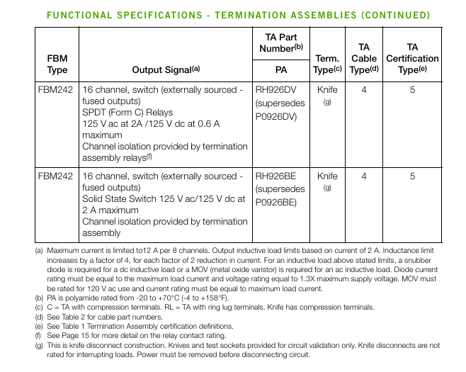
Terminal Components (TAs) Details
(1) Core functions
The terminal components are installed through DIN rails to connect the on-site I/O signals with the FBM subsystem, providing functions such as signal conditioning, surge light isolation, external power connection, and fuse protection. In most scenarios, no additional terminal equipment is required.
(2) Classification and specifications
Low voltage discrete output TA: suitable for<60V DC voltage, with split band fuse protection (single channel 3.15A filled fuse, current limiting 2A) and no fuse protection (users need to configure intermediate relays or fuse terminal blocks between TA and on-site equipment themselves). The power supply can come from FBM 24V DC auxiliary power supply or on-site power supply.
- OMRON
- ABB
- General Electric
- EMERSON
- Honeywell
- HIMA
- ALSTOM
- Rolls-Royce
- MOTOROLA
- Rockwell
- Siemens
- Woodward
- YOKOGAWA
- FOXBORO
- KOLLMORGEN
- MOOG
- KB
- YAMAHA
- BENDER
- TEKTRONIX
- Westinghouse
- AMAT
- AB
- XYCOM
- Yaskawa
- B&R
- Schneider
- KONGSBERG
- NI
- WATLOW
- ProSoft
- SEW
- ADVANCED
- Reliance
- TRICONEX
- METSO
- MAN
- Advantest
- STUDER
- DANAHER MOTION
- Bently
- Galil
- EATON
- MOLEX
- DEIF
- B&W
- ZYGO
- Aerotech
- DANFOSS
- Beijer
- Moxa
- Rexroth
- Johnson
- WAGO
- TOSHIBA
- BMCM
- SMC
- HITACHI
- HIRSCHMANN
- Application field
- XP POWER
- CTI
- TRICON
- STOBER
- Thinklogical
- Horner Automation
- Meggitt
- Fanuc
- Baldor
- SHINKAWA
- Other Brands
- UniOP
- KUKA
- Iba
- Beckhoff
-
 OMRON C60H C6DR DE V1 Sysmac PLC
 -
 MITSUBISHI ELECTRIC A2ACPU21 S1 CPU Module
 -
 ABB BAILEY INNPM12 Network Process Module
 -
 HONEYWELL 620 0073C IPC PLC Module
 -
 Mitsubishi 15050 PR02B PLC Circuit Board
 -
 SIEMENS 6SY7000 0AC37 Drive Control Module
 -
 OMRON TJ2 ECT16 Traxial EtherCAT Controller
 -
 GE Fanuc IC698PSD300D Power Supply Module
 -
 Texas Instruments Series 505 16 Position Base
 -
 OMRON YASKAWA SGDH 10DE OY Servo Drive
 -
 Allen‑Bradley 440G-MT Safety Interlock Switch Specs
 -
 Rubycon PD27A 24V 8A Power Supply Module
 -
 SK-H1-GDB1-F11D PLC Gate Driver Board Kit
 -
 VIPA 441-4UA14 451-4UA14 PLC Module Rack
 -
 Mitsubishi FX5U-80MT ESS PLC Controller Specs
 -
 Mitsubishi Q64TCRTN Temperature PLC Module
 -
 GE 1C31170G Rev10 PLC Circuit Board Module
 -
 Schneider TWDLMDA40DTK PLC Controller Module
 -
 Omron FQM1-MMA22 Motion Control Module Specs
 -
 OMRON CJ1W-NCF71 Position Control Unit Specs
 -
 Schneider TSXETY4103 Ethernet Module
 -
 Mitsubishi Q12PHCPU Process CPU
 -
 Yaskawa 3G3HV-A4022-CE AC Drive
 -
 Cincinnati Milacron 3-533-0669G Temperature Control Board
 -
 Allen Bradley 20AC030A3AYNANC0 PowerFlex 70 Drive
 -
 Siemens 6ES7314-6BG03-0AB0 CPU 314C-2 DP
 -
 Carrier 17EX54007903 PLC Module
 -
 OMRON CS1W-V600C12 ID Controller Module
 -
 Honeywell 51402755-100 PCB Card
 -
 Heidenhain ECN 113 Rotary Encoder
 -
 OMRON B7AM-8B16 I/O Terminal Block
 -
 Fanuc A06B-6110-H026 Power Supply Module
 -
 Schneider TSXETG3021 Ethernet Gateway
 -
 OMRON CS1W-CLK21-V1 Controller Link Unit
 -
 NP1W6406T-Z704 PLC I/O Module
 -
 OMRON CJ1W-DA08C Analog Output Module
 -
 Yaskawa 3G3HV-A4022-CE AC Drive
 -
 OMRON NB7W-TW01B CP1L-EL20DR-D Power Panel
 -
 OMRON C500-NC103-E Position Control Unit
 -
 Steag Hamatech PLC DCS Servo Control System
 -
 Siemens 6SN1123-1AA00-0DA1 Power Supply Module
 -
 GE IC693CHS391H CPU & AD693CMM301A PLC Module
 -
 Siemens 6FC5303-0AF23-1AA1 PLC Control Panel
 -
 Square D CM4000T PowerLogic Circuit Monitor J1 F16
 -
 Siemens 6FX5002-5DG10-1BA0 MOTION-CONNECT 500 Cable
 -
 Schmersal SRB324ST 101195504 Safety Relay 24V
 -
 Mitsubishi 15050-PR02A PLC Circuit Board Module
 -
 OMRON CQM1-AD041 Analog Input PLC Module
 -
 Beckhoff EL5042 EtherCAT PLC Terminal Module
 -
 OMRON C200HW-MC402-E Motion Control Unit
 -
 C36TC0UA1100 Industrial Temperature Controller
 -
 NL8048BC24 12 Industrial Control LCD Module
 -
 OMRON R88D Servo Drive and Motor System
 -
 OMRON CS1W CLK21 V1 Controller Link Module
 -
 OMRON YASKAWA R7M A20030 S1 D Servo Motor
 -
 SIEMENS 6AV2128 3KB06 0AX1 Unified Comfort Panel
 -
 Schneider Electric METSEPM8240 PowerLogic Meter
 -
 Advanced AMCI 1PLC 1 31F Programmable Limit Switch
 -
 ABB PM582 ETH Programmable Logic Processor
 -
 SIEMENS 6FC5110 0CB01 0AA0 CPU Control Board
 -
 Schleicher P03GS13A CPU Module
 -
 Siemens 6SN1123-1AA00-0BA1 Power Module
 -
 Mitsubishi A1S61PN Power Supply Module
 -
 Yaskawa CPS-IONB DC Power Supply Module
 -
 Siemens 6ES7215-2BD00 CPU 215-2
 -
 Mitsubishi A2ACPU MELSEC PLC System Kit
 -
 ProSoft 3150-MCM Communication Module
 -
 Mitsubishi OSE104ET Incremental Encoder
 -
 OMRON CJ1W-AD081-V1 Analog Input Module
 -
 Broadcom BCM5464A1KRB Quad Port Ethernet IC
 -
 Modicon M221-24IO TM221C24 PLC 24 PNP Transistor
 -
 Allen-Bradley 1321-3R160-B Line Reactor 3R160B
 -
 Beckhoff CX1020-0012 Embedded PLC Module Specs
 -
 Turck BL20-PF-24VDC-D Power Feed Module Specs
 -
 Siemens 6SY7000-0AC37 Power Supply Module
 -
 Yaskawa SGDH-10DE-OY 1kW 400V Servo Drive Specs
 -
 Omron 3G3SV-BB015-E 1.5kW 220V VFD Specs
 -
 Uni-Pro CPU91-PLC J 23.020167X Processor Module
 -
 PASABAN MTC-3044 PLC Rack Power Supply 4835-A
 -
 XYCOM 3015T Operator Interface Panel BIN4.4.4
 -
 OMRON CJ1W-MD261 Mixed I/O Module
 -
 Omron NJ301-1100 PLC CPU eCat EIP Specs
 -
 Omron F500-C15-ETN Vision System PLC Module
 -
 Modicon M241-24IO TM/T2UK PLC with Ethernet
 -
 SIXNET YS-800-001 RTU PLC Module
 -
 BEMAC UST-202-D Interface Board 1307D V08B2
 -
 Yaskawa JANCD-MMOIC-02 Drive Circuit Board
 -
 ABB 3BSE005028R1 SDCS-COM-1 Comm Board
 -
 Omron 3G3MX2-A4110 A4150 Inverter Drives Specs
 -
 KEYENCE CA-E100 PLC Module
 -
 GE IC693ALG223-GB Analog Input Module Specs
 -
 ABB BAILEY IMMFP01 Multi Function Processor System
 -
 SIEMENS 6FC5372 0AA00 0AA1 NCU 7202 Controller
 -
Modicon TM241CE4 40I O Transistor Programmable Controller
-
 SIEMENS 6ES7 315 2EH13 0AB0 CPU 3152 PN DP
 -
 NORIS A1 91 PCB Card Rack Module System
 -
 SIEMENS 6ES7 313 5BE01 0AB0 Compact CPU
 -
 SCHNEIDER ELECTRIC S144B MICROLOGIC 60A Trip Unit
 -
 CNI PLC269 v3 Control Module Board Rev H
 -
ABB BAILEY IIMCP02 Processor Module
-
 OMRON NT20S ST121 EV3 Operator Interface Terminal
 -
 OMRON NS-CA001 Video Input Unit
 -
 GE Fanuc IC695CHS012 RX3i Backplane
 -
 Allen Bradley 2711E-K14C6 PanelView 1400e Terminal
 -
 Siemens Sinamics CCB 10000432.71 Power Cell
 -
 Siemens 6SL3210-1SE21-8UA0 Power Module PM340
 -
 Yaskawa CIMR-F7A20P4 AC Drive
 -
 Beckhoff EP1918-0002 EtherCAT Box I/O Module
 -
 OMRON CQM1-TC001 Temperature Control Module
 -
 GE Fanuc SGHA36AT0400 Industrial Contactor
 -
 OMRON NJ501-1500 PLC Machine Automation Controller
 -
 Mitsubishi MAZAK QX084 Power Supply MELDAS 500 CNC
 -
 B&R 0AC808.9 PLC Automation Module
 -
 OMRON CP1H-XA40DT1-D PLC Module
 -
 G&W Electric PLC15 5111 011 15kV Capnut Assembly
 -
 GE DS200SLCCG3AGH PCB Circuit Board
 -
 Siemens SINUMERIK 6FC3981-4FD PLC Extension
 -
 OMRON F300-DC I/O Image Processing Unit
 -
 FANUC A06B-0314-B002 AC Servo Motor
 -
 GC-S84 Programmable Controller Logic Module
 -
 PASABAN MONTELEC MTC3001-DC Drive Control PLC
 -
 Allen Bradley 100E460EJ11 Auxiliary Contactor
 -
 Bosch Rexroth 1070075337-101 Card Parameters
 -
 HMS Anybus AB7646-F Gateway Specifications
 -
 Bosch 062633-303401 CNC Servo PLC Card
 -
 TI 500-5023 Series PLC Power Supply
 -
 Siemens C98043-A7002-L1-12 Circuit Board
 -
 Omron E5CC-RX3A5M-000 Controller


