
Yokogawa STARDOM FCN-500 Autonomous Controller
Process control: supports continuous control (PID regulation, ratio control), sequential control (logical interlocking, step control), and adapts to complex industrial processes (such as temperature control of chemical reaction vessels and pressure regulation of oil and gas pipelines);
Data acquisition and measurement: Real time acquisition of analog quantities (4-20mA, RTD/TC temperature signals), digital quantities (24V DC switch signals), and pulse quantities (frequency/pulse counting), with a measurement accuracy of ± 0.1% FS, meeting industrial grade metrology requirements;
Multi protocol communication: compatible with mainstream industrial buses such as FOUNDATION Fieldbus, HART, Modbus, PROFIBUS-DP, CANopen, etc., supporting interconnection with Yokogawa CENTUM VP DCS, ProSafe RS safety systems, and third-party SCADA (such as Schneider and Siemens systems);
High reliability design: Key components (CPU, power supply, communication bus) support redundant configuration, module hot plugging, wide temperature environment adaptation (-20~+70 ℃ optional), meeting the uninterrupted operation requirements of industrial sites.
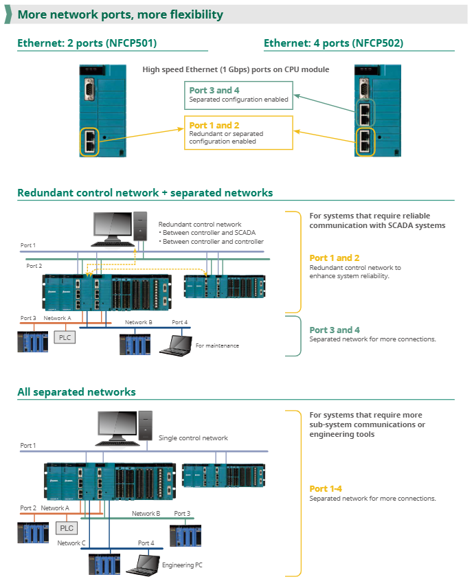
Expansion unit: Connected to the control unit through the E2 bus, each control unit can expand up to 8 expansion units, supporting mixed base configuration (long+short) to achieve flexible expansion of I/O points;
Redundant configuration: CPU, power supply, E2 bus, and Ethernet can all be redundant, with a redundancy switching time of less than 100ms to ensure seamless switching in case of faults.
2. Typical System Topology Example
plaintext
[Upper System] ← Ethernet (Modbus TCP) → [FCN-500 Control Unit (Redundant CPU+Power Supply)]
↓ (E2 bus)
[Extension Unit 1 (AI/AO module)] ←→ [On site sensors/actuators]
↓
[Expansion Unit 2 (DI/DO Module)] ←→ [Valve/Pump Control Circuit]
↓
[Expansion Unit 3 (Fieldbus Module)] ←→ [HART/Fieldbus Smart Devices]
Engineering development and operation characteristics
1. Programming and configuration tools
FCN-500 comes with Yokogawa Engineering Tool Kit, supporting IEC 61131-3 standard programming language to reduce development difficulty:
Logic Designer: a control program development tool that supports five languages: FBD (Function Block Diagram), LD (Ladder Diagram), ST (Structured Text), SFC (Sequential Function Diagram), and IL (Instruction List). It provides drag and drop programming and template libraries (such as PID control blocks and flow calculation blocks);
Resource Configurator: a hardware configuration tool that maps logical I/O to physical modules, supports IP address and communication protocol parameter settings, and does not require manual driver writing;
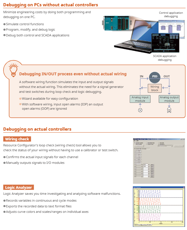
Simulator function: Supports hardware free debugging, can simulate control logic and I/O signals on a PC, and shorten the on-site debugging cycle.
2. Operations and diagnostic capabilities
Module hot plugging: All I/O modules and power modules support online replacement, and the configuration is automatically loaded after replacement without the need for system shutdown;
Status monitoring: The CPU module comes with an LCD display screen and LED indicator lights, which display the system status (running/faulty) and I/O module health in real time; Support exporting logs (fault records, operation records) through SD card without the need to connect to a PC;
Remote operation and maintenance: Remote diagnosis can be achieved through Web HMI or Yokogawa PRM (Plant Resource Manager) system, supporting I/O channel fault location, module firmware online upgrade, and reducing on-site maintenance costs.
Key modules and selection information
1. Core module model and function
Module Type Model Example Core Functions
CPU module NFCP501 (2 Ethernet ports) with 2 Gigabit Ethernet channels, supporting Modbus/DNP3 protocols, with optional single/redundant configurations
NFCP502 (4 Ethernet ports) 4 Gigabit Ethernet channels, supporting independent network partitioning (such as control network+operation and maintenance network)
Power module NFPW441 (100-120V AC) system power supply (5.1V DC)+on-site power supply (24V DC), supports redundancy
NFPW444 (24V DC) DC input power supply, suitable for industrial 24V DC bus power supply scenarios
Analog input module NFAI135 (8 channels) 4-20mA input, channel isolation, accuracy ± 0.1% FS, supports HART protocol
NFAR181 (12 channel) RTD input (platinum resistance 100 Ω/1000 Ω), supports wire breakage detection
Digital output module NFDV551 (32 channels) 24V DC output, channel isolation, supports fail safe output (Fallback)
NFDR541 (16 channel) relay output (24-125V DC/100-240V AC), suitable for high-power loads (such as motor contactors)
Communication module NFLF111 (4-port) FOUNDATION Fieldbus communication, supporting 16 devices per port
NFLP121 (1 port) PROFIBUS-DP master station, supporting 123 slave devices
Expansion bus module N2EB100 E2 bus interface module, realizing the connection between control unit and expansion unit, supporting redundancy
2. Key dimensions for selection
Control scale: Select the base type (long/short/compact) and the number of expansion units based on the number of I/O points. A single system can support up to 79 I/O modules;
Environmental requirements: Standard temperature modules (0-55 ℃) are selected for conventional environments, wide temperature models (-20~+70 ℃) are selected for low/high temperature scenarios, and G3 coating is optional for corrosive environments;
Communication protocol: Select the communication module based on the type of on-site equipment (such as selecting NFAI135 AI module for HART devices and NFLF111 module for Fieldbus devices);
Reliability requirements: For critical scenarios (such as chemical reaction control), CPU, power supply, and E2 bus redundancy should be configured. For non critical scenarios (such as regular monitoring), menu configuration is available.
- OMRON
- ABB
- General Electric
- EMERSON
- Honeywell
- HIMA
- ALSTOM
- Rolls-Royce
- MOTOROLA
- Rockwell
- Siemens
- Woodward
- YOKOGAWA
- FOXBORO
- KOLLMORGEN
- MOOG
- KB
- YAMAHA
- BENDER
- TEKTRONIX
- Westinghouse
- AMAT
- AB
- XYCOM
- Yaskawa
- B&R
- Schneider
- KONGSBERG
- NI
- WATLOW
- ProSoft
- SEW
- ADVANCED
- Reliance
- TRICONEX
- METSO
- MAN
- Advantest
- STUDER
- DANAHER MOTION
- Bently
- Galil
- EATON
- MOLEX
- DEIF
- B&W
- ZYGO
- Aerotech
- DANFOSS
- Beijer
- Moxa
- Rexroth
- Johnson
- WAGO
- TOSHIBA
- BMCM
- SMC
- HITACHI
- HIRSCHMANN
- Application field
- XP POWER
- CTI
- TRICON
- STOBER
- Thinklogical
- Horner Automation
- Meggitt
- Fanuc
- Baldor
- SHINKAWA
- Other Brands
- UniOP
- KUKA
- Iba
- Beckhoff
- ADLINK
-
 GE Fanuc VMIVME-5588 High-speed Reflective Memory Board
 -
 VMIC VMIVME-5565 Reflective Memory Board
 -
 VMIC VMIVME-2127 Voltage Source Digital Output Board
 -
 VMIC VMIVME 4512 Analog VME Process PCB Assembly
 -
 GE Fanuc VMIVME-3122-022 Analog I/O Module
 -
 VMIC VMIVME 5576 High Speed Fiberoptic Network Board
 -
 FANUC VMIVME-7452 VMEbus Analog I/O Board
 -
 FANUC VMIVME-2210 VMEbus Digital Output Board
 -
 FANUC VMIVME-7750-734000 VMEbus Single Board Computer
 -
 VMIC VMIVME 2210 VMEbus DO 28V Digital Output Board
 -
 VMIC VMIVME DR11W VMEbus DMA Interface Module
 -
 VMIC VMIVME-2536-200 5V Optically Coupled Digital I/O Board
 -
 VMIC VME-7754 VMIVMF7754-259000 VMEbus Control Card
 -
 VMIC 2170A VME Interface Board
 -
 GE VMIC PMC-5565PIORC-210000 Reflective Memory PMC Node Card
 -
 VMIC VMIVME-7750-750000 VME Single Board Computer
 -
 VMIC VMIVME-7751 VME Single Board Computer
 -
 VMIC 332-004512 Analog VME Process Board
 -
 VMIC VMIVME2528 VME Interface Board
 -
FANUC VMIVME-2120 VME Bus Interface Board
-
 FANUC VMIVME-2540 VME Bus Interface Board
 -
 FANUC VMIVME-3230 VME Bus Interface Board
 -
 FANUC VMIVME-4514 VME Bus Interface Board
 -
 ETEL DSB2S154-211E-000H Servo Amplifier
 -
 ETEL DSCQT112-111-000 Motion Control Module
 -
 ETEL LMG20-050-3QB-211A Servo Motor – High Torque Linear
 -
 ETEL EU-LCP-0-0-1000-01 Communication Card
 -
 ETEL DSA2P174ZA-033A Servo Amplifier Driver
 -
 ETEL EA-P2M-400-15/40A-0100-00 Servo Driver
 -
 ETEL DSC2P152-111-000 Servo Drive Amplifier
 -
 ETEL LMS15-050-3UA-209A Linear Motor
 -
ETEL DSC2P152-111D-000A Controller
-
 ETEL DSB2P131-111E-000B Digital Servo Amplifier Position Controller
 -
 ETEL DSO-PWR111C-000B Power Supply Module
 -
 ETEL DSCDP324-321F-000C Servo Driver
 -
 ETEL DSC2P152-111B-000D Controller
 -
 ETEL DSB2P142-111E-000H Circuit Board
 -
 ETEL LMG05-030-3QA-H01 Linear Motor
 -
 ETEL DSC2P152-111F-000A Controller
 -
 ETEL DSA2S211ZA Servo Drive
 -
 ETEL DSCDM332-112-000 Drive Module
 -
 ETEL DSCDP334-421-000 Digital Position Controller Servo Drive
 -
ETEL EA-P2M-400-15/40A-0100-00 AccurET Servo Drive
-
 ETEL TMA0140-050-3UB-202B Torque Motor
 -
 ETEL DSA1DL1D.PCB Servo Drive Board
 -
 ETEL DSA2DL 1A Servo Drive
 -
 ETEL DSMAX111B-000B Servo Drive
 -
ETEL DSO-PWS111C-000B Power Supply Module
-
 ETEL DSC2P142-111B-000D Servo Drive Amplifier
 -
 ETEL DSC2P132-111D-000A Servo Drive Amplifier
 -
ETEL DSC2P152-111B-000D Servo Drive Amplifier
-
ETEL DSB2P131-121E-000H Servo Drive Amplifier
-
 ETEL DSB2P142-111E-000H Servo Drive Amplifier
 -
ETEL DSO-PWR112C-000A Power Supply Module – High Power
-
ETEL DSO-PWR111C-000A Power Supply Module
-
ETEL DSB2P121-121E-000H Servo Drive Amplifier
-
 ETEL DSB2S134-111E-000H Digital Servo Amplifier
 -
 ETEL RTMA0140-070-AQN-21E Motor
 -
ETEL DSCDP132-111-000 Dual Controller Circuit Board – Motion Control
-
 ETEL LMS15-050-3UA-209Aft Linear Motor
 -
 ETEL DSCDP324-322G-000A Position Controller
 -
ETEL DSA2P174ZA-033A Servo Amplifier Driver
-
 ETEL DSA2P174ZA-017A Servo Amplifier Driver
 -
 ETEL LMD10-050-3QA-223A Linear Motor
 -
ETEL EU-LGP-0-0-1000-00 PCI Network Card
-
ETEL DSO-PWS111C-000B Power Supply Module
-
ETEL DSC2V174-111C-001A Servo Controller
-
 ETEL EA-P2M-600-15/40A-0000-01 AccurET Modular Position Controller
 -
 ETEL RTMA0140-070-AQN-21B DD Motor
 -
 ETEL DSC2P144-421-000 Servo Driver
 -
ETEL EA-P2M-400-15-40A-0100-00 Servo Drive
-
ETEL DSCDM341-111C-000B Board
-
 ETEL LMD10-050-3QA-223A Motor
 -
ETEL RTMA0140-070-AQN-21E DD Motor
-
 ETEL DSCDM342-111-000 Servo Variator
 -
ETEL DSC2P152-111E-000A Servo Amplifier
-
ETEL LMS15-050-3UA-209A Motor
-
ETEL RTMA0140-070-AQN-21C DD Motor – High Torque Direct Drive
-
 ETEL DSCDP334-421G-000A Servo Drive
 -
Etel DSB2S154-211E-000H Digital Servo Amplifier
-
 ETEL EA-P2M-400-15/40A-0100-00 AccurET Servo Drive
 -
 ETEL DSA2P-174ZA-017A Digital Servo Amplifier
 -
ETEL EA-P2M-400-15/40A-0100-00 Servo Drive
-
ETEL LMP07-100-3TAS-229 Linear Motor Primary Part
-
ETEL LMA11-120-3ZA-359A Linear Motor
-
 ETEL EA-S0M-400-40/80A-0000-00 Drive Power Supply
 -
Etel DSCDP334-421-000 Driver
-
ETEL DSCDM341-111C-000B DSCDM Drive Board
-
Etel DSA1 Digital Servo Amplifier
-
ETEL DSA2P174ZA-033A Servo Amplifier
-
ETEL DSCDM342-111-000 Servo Verifier
-
 ETEL LMS15-050-3UA-209A Linear Motor
 -
ETEL P2M-048-2.5/5A AccurET Position Controller – Modular
-
ETEL LMD10-050-3QA-223A Linear Motor – Compact Precision
-
 ETEL EA-P2M-400-05/10A-0000-01 Drive – Precision Motion
 -
ETEL LMP07-100-3TAS-229 Linear Motor Primary Part
-
 ETEL EU-LGP-0-0-0000-00 Motion Control Card – Precision Control
 -
 ETEL DSC2P152-111E-000A Servo Amplifier
 -
ETEL EA-P2M-400-15/40A-0100-01 Servo Drive
-
 ETEL EA-SOM-300-40/80A-0000-00 AccurET Power Supply Module
 -
ETEL LMG10-1050-3QA-H01 Linear Motor
-
 ETEL EA-SOM-300-40/80A-0000-00 AccurET Modular Power Supply
 -
ETEL EA-P2M-400-15/40A-0100-00 AccurET Servo Drive
-
 ETEL EA-P2M-400-15/40A-0100-01 Servo Driver
 -
Etel RTMA0140-070-AQN-21B High Speed Motor
-
ETEL DSC2P141-111-000 Linear Servo Amplifier
-
ETEL DSB2S134-211E-000H Digital Servo Amplifier
-
ETEL 3LM-23C Motion Controller
-
Etel DSO-SER211-000 Power Add-On Board
-
ETEL DSCDP334-421-000 Servo Drive
-
 CTI-Cryogenics 8116071G001 Enhanced On-Board 8F Cryopump
 -
ETEL LMD10-050-3QA-223A Linear Motor
-
Etel DSO-SER211-000 Servo Card Power Add-On
-
ETEL LMG05-050-3QA-213A Linear Motor
-
Etel DSO-SER211-000 Power Add-On Board
-
ETEL EU-LGP-0-0-0000-00 Motion Control Card
-
ETEL EA-P2M-400-15/40A-0100-00 AccurET Servo Drive
-
 ETEL DSA2P1540A Digital Servo Amplifier
 -
ETEL DSC2P131-111-000 Drive Board
-
ETEL DSC2P131-111D-000A Servo Drive
-
Etel SA-IL 03-208 Linear Motor Section 208mm
-
 ETEL EA-P2M-300-4/7.5A-0000-01 AccurET Position Controller
 -
ETEL DSO-SER211-000 Power Board
-
ETEL DSC2P131-111F-000A Servo Amplifier
-
ETEL DSA1P6242B Digital Servo Amplifier
-
ETEL DSC2P131-111B-000B Regulator
-
ETEL DSA2P1540A Digital Servo Amplifier
-
ETEL EA-P2M-048-2.5/5A-0100-01 Drive


