
YOKOGAWA FIO System (compatible with Vnet/IP) Hardware Specification Manual
YOKOGAWA FIO System (compatible with Vnet/IP) Hardware Specification Manual
Overview
This document is the general specification sheet for Yokogawa Electric's FIO (Fieldnetwork I/O) system (document number: GS 33K50F10-50E), updated to version 8 in September 2014. Its core purpose is to guide the deployment, module selection, and installation of the system in CENTUM VP (Vnet/IP). As a field I/O solution, the FIO system is connected to the field control unit (FCU) through ESB/optical ESB/ER bus, supporting dual redundancy configuration and adapting to the signal acquisition and control needs of various industrial scenarios. The module types cover all categories such as analog, digital, and communication, and meet multiple international safety and EMC standards.
System architecture and bus specifications
(1) Overall architecture
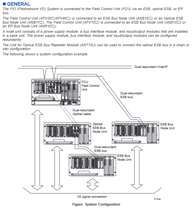
The FIO system is based on the core architecture of "FCU+node unit+bus". The node unit includes a power module, a bus interface module, and an I/O module, which can be extended in a chain/star configuration through an optical ESB bus relay unit (ANT10U). It supports dual redundancy configuration (power supply, bus, I/O module) to ensure high availability of the system.
(2) Three major bus core specifications
Bus type suitable for FCU transmission rate, transmission distance support, node unit topology structure
ESB bus AFV30 /AFV40 /AFV10 128 Mbps ≤ 10m ANB10 bus type
Optical ESB bus AFV30 /AFV40 128 Mbps up to 50km (ANT411 relay) ANB11 , ANT10U chain/star type
ER bus AFV10 10 Mbps YCB141: ≤ 185m; Hybrid cables must meet the formula limit ANR10 bus type
Core Component Details
(1) Control Unit (FCU)
Model series type installation method adaptation bus
AFV30 (S/D) standard/dual redundant 19 inch rack mounted ESB/optical ESB bus
AFV40 (S/D) standard/dual redundant with cabinet ESB/optical ESB bus
AFV10 (S/D) standard/dual redundant 19 inch rack mounted ESB/ER bus
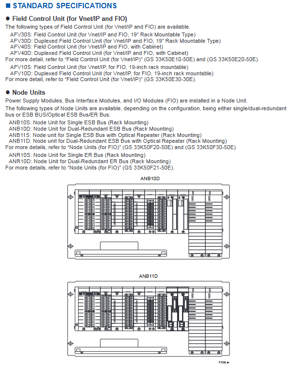
(2) Node unit and relay unit
Unit type, model series, functional redundancy support
ESB node unit ANB10 (S/D) connects to the ESB bus and installs I/O module single/dual redundancy
Optical ESB node unit ANB11 (S/D) is connected to the optical ESB bus with optical relay single/dual redundancy
ER node unit ANR10 (S/D) is connected to the ER bus and installed with I/O module single/dual redundancy
Optical ESB relay unit ANT10U optical ESB bus extension, supporting chain/star type-
(3) I/O module classification and core parameters
The FIO system I/O modules cover 6 major categories, with the following key parameters (representative models):
Module type, representative model, number of channels, signal type, isolation characteristics, power consumption (5V DC/24V DC)
Analog input AAI141 16 4~20 mA non isolated 310 mA/450 mA
Analog output AAI543 16 4~20 mA isolated 230 mA/540 mA
TC/mV input AAT141 16 TC (J/K/E, etc.), -100~150 mV isolation 450 mA/-
Digital input ADV151 32 24 V DC isolated 500 mA/-
Digital output ADV551 32 24 V DC isolated 700 mA/-
Communication module ALF111 4-port Foundation Fieldbus (31.25 kbps) -500 mA/-
Turbomachinery module AGP813 26 high-speed protection signal isolation 900 mA/-
Built in isolation barrier module ASI133 8 4~20 mA isolation 150 mA/450 mA
Environmental and power specifications
(1) Environmental requirements
Environmental parameters, working status, transportation/storage status
Temperature range of 0-60 ℃ (standard); -20~70 ℃ (wide temperature option) -40~85 ℃ (wide temperature option)
Humidity 5-95% RH, no condensation 5-95% RH, no condensation
Temperature change rate ± 10 ℃/h ± 20 ℃/h
Vibration 1-14Hz: displacement ≤ 0.25mm; 14-100Hz: acceleration ≤ 2.0 m/s ²-
Dust ≤ 0.3 mg/m ³-
Altitude ≤ 2000 meters-
(2) Power specifications
Communication input: 100-120V AC (± 10%) or 220-240V AC (± 10%), frequency 50/60Hz (± 3Hz), distortion ≤ 10%
DC input: 24V DC (± 10%), ripple rate ≤ 1% p-p
Instantaneous power outage tolerance: ≤ 20ms (under rated AC voltage)
Grounding requirements: independent grounding, grounding resistance ≤ 100 Ω
Connection method and terminal configuration
(1) Signal connection method
The module supports three connection methods to adapt to different on-site requirements:
Pressure clamping terminal: directly connected to on-site equipment, supporting single/double redundant terminal blocks
Specialized cables (such as YCB301, YCB141): connecting modules to terminal boards
MIL connector cable: No terminal block required for direct connection, equipped with anti loosening sheath (ACCC01)
(2) Example of Terminal and Module Combination
Module type pressure clamping terminal dedicated cable MIL connector cable
Analog I/O (AAI141/AAI543) Support Support Support
Digital I/O (ADV151/ADV551) supports partial support
Communication module (ALF111/ALP111) partially supported but not supported
Built in isolation barrier module (ASI133/ASD143) is not supported
Installation restrictions and precautions
(1) Power capacity limitation
Module installation must comply with the "factor summation" rule to avoid power overload:
Installation location application scenario factor summation threshold
ANB10 /ANB11 /ANR10 Non hazardous area ≤ 100
ANB10 - E/ANB11 - E/ANR10 - E Hazardous Area ≤ 88
ANB10 F/ANB11 F/ANR10 F Hazardous area ≤ 80
AFV10D/AFV30D (dual redundancy) non hazardous area factor A ≤ 20; Factor A+Factor B ≤ 65
(2) Spacing and isolation requirements
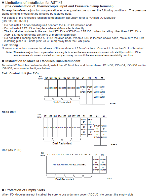
The intrinsic safety zone and non intrinsic safety zone must maintain a distance of ≥ 50mm. The node unit (ANB10 ) needs to be equipped with an insulation partition (T9083NA), and the FCU (AFV10 /AFV30 ) needs to be equipped with an insulation partition kit (T9083ND);
The built-in isolation barrier module needs to be installed separately from other modules to avoid electromagnetic interference.
(3) Special environment and module limitations
Wide temperature environment (60-70 ℃): A maximum of 4 IOMs can be installed on a single node, and slots need to be left between modules. Installation of AAI543- 6 /- F (quick response type) is prohibited;
TC input module (AAT141/AAT143): It should be kept away from heat sources (such as CP461, bus interface module), avoid direct airflow, and can only be installed adjacent to designated modules (AAT141, AAR181, etc.);
Dual redundancy configuration: I/O modules need to be installed in paired slots (IO1-IO2, IO3-IO4, etc.), and empty slots need to be protected with a false cover plate (ADCV01).
Compliance standards
Safety standards: CSA, CE Marking, EAC Marking;
EMC standards: CE Marking, EAC Marking, RCM, KC Marking (excluding built-in isolation barrier modules);
Explosion proof standards: CSA/FM Non Intrinsic, Type n, Type i, FM certified.
- OMRON
- ABB
- General Electric
- EMERSON
- Honeywell
- HIMA
- ALSTOM
- Rolls-Royce
- MOTOROLA
- Rockwell
- Siemens
- Woodward
- YOKOGAWA
- FOXBORO
- KOLLMORGEN
- MOOG
- KB
- YAMAHA
- BENDER
- TEKTRONIX
- Westinghouse
- AMAT
- AB
- XYCOM
- Yaskawa
- B&R
- Schneider
- KONGSBERG
- NI
- WATLOW
- ProSoft
- SEW
- ADVANCED
- Reliance
- TRICONEX
- METSO
- MAN
- Advantest
- STUDER
- DANAHER MOTION
- Bently
- Galil
- EATON
- MOLEX
- DEIF
- B&W
- ZYGO
- Aerotech
- DANFOSS
- Beijer
- Moxa
- Rexroth
- Johnson
- WAGO
- TOSHIBA
- BMCM
- SMC
- HITACHI
- HIRSCHMANN
- Application field
- XP POWER
- CTI
- TRICON
- STOBER
- Thinklogical
- Horner Automation
- Meggitt
- Fanuc
- Baldor
- SHINKAWA
- Other Brands
- UniOP
- KUKA
- Iba
- Beckhoff
-
 Basler DECS-200-2L Digital Excitation Control
 -
 Basler BE1-47N Voltage Phase Sequence Relay
 -
 Basler AEC63-7 Analog Excitation Controller 220-277V
 -
 Basler BE1-50/51B-107 Overcurrent Relay
 -
 Basler Electric BE1‑32R BE1‑E1P‑BON0F Protective Relay
 -
 Basler BE1-25 Solid State Time Overcurrent Relay M1EA6PA5S1F
 -
 Basler MVC 232 Manual Voltage Control Module 90 37000 103 60VAC 55VDC
 -
 Basler RAL6144-16GM Racer GigE Line Scan Camera
 -
 Basler SSR 63-12 Static Voltage Regulator
 -
 Basler BE1-51A Overcurrent Relay
 -
 Basler BE1-87T Solid State Protective Relay
 -
 Basler SR4A2B01B3A Static Voltage Regulator
 -
 Basler SSR 32-12 Static Voltage Regulator
 -
 Basler TRR00696 Transformer 1KVA 115V
 -
 Basler DECS-100-B15 AVR Replacement
 -
Basler BE1-27 Under-Voltage Relay
-
 Basler ACA2000-50GM Interface Module
 -
 Basler AEC63-7 Analog Excitation Controller
 -
 Basler PRS 250 Veri-Sync Relay
 -
 Basler SR4A-2B15B3A Static Voltage Regulator
 -
Basler BE1-32R Power Relay
-
Basler SR8A-2B06B3E Static Voltage Regulator
-
Basler BE1-81 O/U Frequency Relay
-
 Basler BE1-51A-K2E-W6M-B1N0F Overcurrent Relay
 -
Basler BE1-851 Overcurrent Relay G3A1S1 – 48-125V AC/DC
-
 Basler BEI-51 Overcurrent Relay – NSN 5945-01-293-2363
 -
Basler Electric L301KC Protective Relay – L301KC
-
 Basler DECS-100-B15 Automatic Voltage Regulator – Generator AVR
 -
 Basler SR4A-2B15B3A Static Voltage Regulator – SR4A2B15B3A
 -
 Basler UF 312 Under Frequency Protective Module – 9094700100
 -
Basler Electric MVC 232 Manual Control Module – 60VAC 55VDC 20A
-
Basler PRS 250 Veri-Sync Relay – Generator Synchronizing Relay
-
 Basler DECS-100-A05 Digital Regulator Review
 -
 Basler AEM-2020 Analog Expansion Module Specs
 -
 Basler DECS-100-B15 Digital Excitation Specs
 -
Basler Electric 9125600106 Regulator Component
-
Basler BE1-51A-K1E-W6M-B1N0F Overcurrent Relay
-
 Basler MVC-301 MVC 300 Excitation Controller
 -
 Basler SSR 32-12 Static Voltage Regulator
 -
 Basler 9-2849-00-101 Control Module
 -
Basler BE1-51A Overcurrent Relay
-
 Basler BE1-51/27R Overcurrent Relay
 -
 Basler BE1-51 Overcurrent Relay
 -
 Basler SR8A-2B15B3A Static Voltage Regulator
 -
 Basler BE32965001 Transformer and Timer Board
 -
 Basler 9174700100 EL200-7 Excitation Limiter
 -
 Basler BE2000E AVR Voltage Regulator
 -
Basler BE1-87G Differential Relay
-
 Basler BE21834001 Generator Control Module
 -
Basler DECS-100-B15 AVR
-
 Basler D90 96801 100 PCB Card
 -
 Basler XR2002F Voltage Regulator (110 VAC, 48-480 Hz)
 -
 Basler SR8A-2B14B3A Regulator
 -
 Basler 9561500100 Module
 -
 Basler DECS-400 BE1-11 System
 -
 Basler DECS-100-B15 Excitation Control
 -
 Basler SCP 210 Frequency Controller
 -
Basler SR4A-2B15B3A Static Voltage Regulator
-
Basler BE1-32R Power Relay
-
 Basler PIA2400-17GM Power Interface Adapter
 -
 Basler MVC 232 Manual Voltage Control Module
 -
 Basler SSR 32-12 Static Voltage Regulator
 -
Basler 5MW AVR Generator Voltage Regulator
-
 Basler VR63-4B Voltage Regulator
 -
Basler DECS-100-A05 AVR for Engine Generator
-
Basler DECS-100-B15 Automatic Voltage Regulator
-
Basler BE1-32R Directional Power Relay
-
Basler BE1-87B Differential Relay
-
 Basler UFOV 260A Protective Module
 -
 Basler 9-2614-02-100 PCB Rev M
 -
Basler DECS-100-B15 Digital AVR
-
 Basler 9284900103 PS DECS-400N
 -
 Basler D4N3H1U Intertie Protection
 -
 Basler DECS-100-B15 A15 AVR
 -
 Basler KR4F Voltage Regulator
 -
 Basler BE26434 T14 Transformer
 -
 Basler SR8A-2B15B3A Regulator
 -
 Westinghouse 774B472A12 AR Relay
 -
Basler DECS-100-B15 AVR
-
Basler XR2002F Regulator 110V
-
Basler SR125-E Static Regulator
-
Basler SSR 125-12 Regulator
-
Basler MOC2599 Motor Pot
-
 Basler BE1-DFPR Feeder Relay
 -
 Basler CBS 305 Current Boost
 -
Basler BE1-25 AutoSync
-
Basler MVC 300 Voltage Control
-
 Basler BE3-25A AutoSync
 -
 Basler KR7FF Static Regulator
 -
Basler 90-49000-100 Regulator
-
 Basler 880 kVA Dry Type Transformer Specs
 -
Basler Electric BE1-25 Sync-Check Relay Specs
-
 Basler SSR 125-12 Voltage Regulator Specs
 -
 Basler Electric BE1-851 Overcurrent Relay Review
 -
Basler Electric 149D930G02 Control Sub-Assembly
-
 Basler Electric BE1-81O/UT Frequency Relay Specs
 -
 Basler Electric BE1-51/27C Overcurrent Relay
 -
 Basler Electric 149D956G02 Industrial Component
 -
Basler Electric BE1-51A Overcurrent Relay Specs
-
 Basler Electric BE1-40Q Loss of Excitation Relay
 -
Basler DECS-200 Excitation Control System
-
 Basler DECS-200 Voltage Regulator 56-277V AC / 125V DC
 -
Basler BE1-87T Transformer Differential Relay
-
 Basler RDP-110-S1 Protection Relay
 -
 Basler BE1-700V Digital Protective Relay
 -
 Basler BE1-951 Overcurrent Protection System
 -
 Basler DECS-300 Digital Excitation Control
 -
 Basler DECS-200 Digital Excitation Control
 -
 Basler DECS-200-1C Excitation Control System
 -
Basler DECS-200-1L Digital Excitation Control
-
 Basler Electric BE1-GPS Generator Protection System
 -
Basler Electric DECS-200-1C Digital Excitation Controller
-
 Basler Electric DECS125-15 Excitation Control with Power Module
 -
Basler Electric BE1-87G Differential Relay
-
 Basler Electric BE1-11 Protection System I5A3M2P2N0EA00
 -
Basler Electric DECS-200-1C Excitation Control System
-
Basler Electric BE1-11g Generator Protection Relay
-
Basler Electric DECS 125-15-B2C1 V2.0.9 Excitation Control
-
Basler Electric BE1-81O/UT3ED1JA7N2F Frequency Relay
-
Basler Electric BE1-81O/UT3EE1YB7N1F Frequency Relay
-
 Basler Electric DECS-200-1L Digital Excitation Control System
 -
Basler DECS125-15-B2C1 Excitation Control
-
 Basler 9507900205 SSR Retrofit Voltage Regulator
 -
 Basler BE2000E Digital Voltage Regulator
 -
 Basler BE1-GPS Generator Protection System
 -
Basler DECS-250-CN1CN1N Digital Excitation Control
-
 Basler DGC-2020 Genset Controller
 -
Basler BE1-81O UT3ED1LA7N0F Frequency Relay (Variant)


