
Rockwell Automation ICS AADvance Controller
Core objective: Define SIF safety application standards (mandatory) and recommendations to ensure that the system meets and maintains the required Safety Integrity Level (SIL), with a maximum support for SIL 3.
Rockwell Automation ICS AADvance Controller
Basic Information and Usage Standards
1. Scope of application and core objectives
Applicable products: AADvance controller series (T9100/T9110 processor modules, T9401/2 digital input modules, etc.) and supporting software (AADvance Workbench 1.4/2.1, AADvance Robust SIS Workstation 2.00), supporting system version 2.011.
Core objective: Define SIF safety application standards (mandatory) and recommendations to ensure that the system meets and maintains the required Safety Integrity Level (SIL), with a maximum support for SIL 3.
2. Key usage requirements
Personnel qualifications: Installation, configuration, operation and maintenance operations must be carried out by professionally trained personnel who are familiar with relevant regulations (such as IEC 61508, NFPA series standards).
Responsibility statement: If the device is used in a manner that does not comply with the manufacturer's regulations, the protective function of the device may become ineffective; Rockwell is not responsible for indirect/consequential damages, and the examples in the manual are for illustration only and do not represent actual application guarantees.
System core features and authentication
1. Core functions and security design
Application scenarios: Suitable for safety critical scenarios such as emergency shutdown (ESD), fire and gas detection, rotating machinery control, burner management, etc., while supporting non safety but business critical control requirements.
Security Capability:
Both fail safe and fault tolerant architectures are supported, and fault tolerance can be realized through two module (1oo2D) or three module (2oo3D) configurations.
Built in comprehensive diagnostic function, capable of detecting hardware/software faults. The faulty module needs to be replaced within the mean time to repair (MTTR) to avoid a decrease in SIL level.
Supports two configurations: "Power Loss Trip (DTT)" and "Power On Action (ETA)", and the number of modules needs to be selected based on SIL level and demand rate (high/low) (see Table 1).
2. Module configuration and SIL compliance requirements
Minimum module configuration for different application scenarios (simplified version of Table 1):
Application type, number of input modules, number of processor modules, number of output modules
SIL 2/3, Low/high demand, DTT 1 2 1
SIL 2, High demand, ETA 2 2 2
SIL 3, High demand, ETA 2 2 2
Note: The single channel digital output module includes a series switch. The DTT scenario supports SIL 3, while the ETA scenario only supports SIL 2; There are no three module output configuration options.
3. International certification and compliance standards
Functional safety certification: Compliant with IEC 61508 SIL 3, certified by an independent certification body.
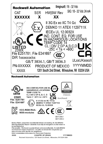
Hazardous environment certification:
North America: Class I, Division 2, Groups A-D (UL 61010-2-201, CSA C22.2 standard).
Europe/UK: ATEX (DEMKO 11 ATEX 1129711X, Ex ec IIC T4 Gc), UKCA (UL24UKEX2993).
International: IECEx (certificate number IECEx UL 12.0032X).
Other compliance: Complies with industry standards such as EN 50156 (furnace control), EN 54 (fire alarm), NFPA 85/86/87 (boilers/ovens/fluid heaters), etc.
Safety lifecycle and management system
1. Safety lifecycle stages
The full lifecycle defined by IEC 61508 must be followed, with core stages including:
Scope definition: Clearly define system boundaries, interfaces (with processes/third-party equipment), and environmental requirements (such as temperature and power).
Hazard and Risk Analysis: Identify hazardous events, trigger sequences, and risk levels as inputs for safety requirements.
System Design and Engineering: Divide system architecture, define security requirement levels for each component, and refine hardware/software design.
Integration and Verification: The application is integrated with the controller to test and verify whether SIF meets SIL requirements (such as response time and fault handling).
Operation and Maintenance: Develop an operation/maintenance plan to ensure the SIL level is maintained during operation; Changes must be strictly controlled, and suspensions must follow safety procedures.
2. Requirements for Safety Management System
Policy and Planning: Functional safety policies need to be developed to clarify measures, responsibilities, and record management (including change control) for each stage of the lifecycle.
Personnel capability: Personnel qualifications need to be evaluated, including engineering experience, functional safety knowledge, regulatory familiarity, etc. Higher qualification requirements are required for high-risk scenarios.
Functional Safety Assessment (FSA): Led by senior personnel independent of the project, it reviews whether the entire lifecycle work meets the requirements.
System Architecture Design (SIL 2/3)
1. SIL 2 architecture
Fault safety architecture: single input (1oo1D), dual processor (1oo1D degraded), single output (1oo1D), triggering a safe state in case of a fault.
Fault tolerant input architecture: dual/triple input (1oo2D/2oo3D), dual processors, single output. When a single input module fails, it will operate in a degraded state while still maintaining safety functions.
High demand architecture: dual input, dual processor, dual output, ensuring that faulty modules are replaced within MTTR to avoid SIF shutdown.
2. SIL 3 architecture
Fault safe I/O+fault-tolerant processor: single input/output, dual/triple processor (1oo2D/2oo3D), downgraded in case of processor failure, dual fault triggers safe state.
Fault tolerant I/O architecture: dual input/output, dual processors, both input/output modules support 1oo2D degradation, suitable for high safety requirements scenarios.
TMR architecture: three inputs, three processors (2oo3D), dual outputs, with the strongest fault tolerance. A single module failure does not affect system operation. When there are two failures, it will be downgraded, and when there are three failures, it will trigger a safe state.
3. Secure network communication
SNCP protocol: SIL 3 certified "Black Channel" protocol, supports Ethernet transmission of secure data, achieves data exchange between controllers through "variable binding", and can be configured as single network (fail safe) or dual network (fault-tolerant).
Peer to Peer communication: Supports SIL 3 data transmission between AADdistance and Trusted controllers, based on master-slave mode, and recommends using redundant networks to ensure availability.
Installation and environmental requirements
1. Non hazardous environment
Environmental conditions: temperature -25 ° C~+60 ° C, pollution level ≤ 2 (IEC 60664-1, only non-conductive pollution, occasional condensation); The burner management application requires an enclosure protection level of IP40 (indoor)/IP54 (outdoor).
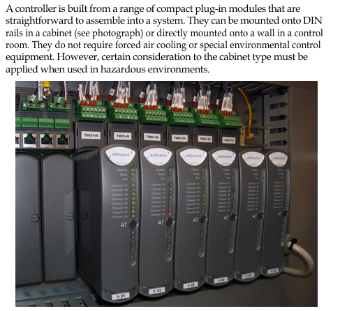
Installation requirements: The module should be installed vertically (ensuring natural heat dissipation), DIN rail or wall mounted, without the need for forced air cooling.
2. Hazardous environment
Special requirements:
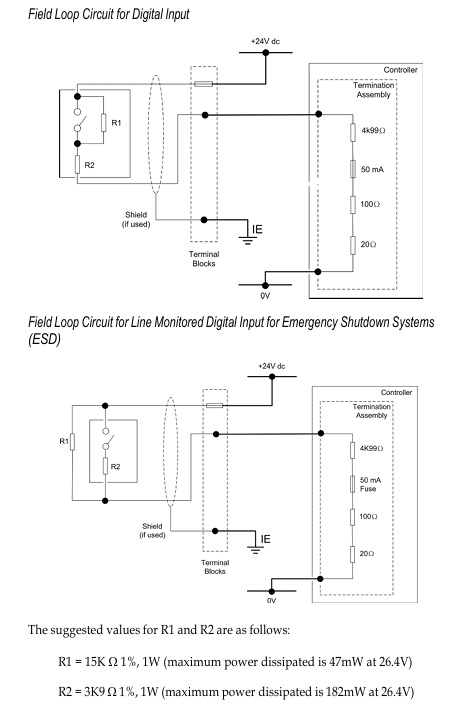
The enclosure protection level is ≥ IP54 (IEC 60079-0/7) and must be marked with "Do not open when powered on".
Grounding wire cross-sectional area ≥ 3.31mm ², wire temperature rating ≥ 85 ° C, only supports vertical installation.
The temperature range is the same as non hazardous environments, and the pollution level is ≤ 2.
Operations and Security Assurance
1. Key daily maintenance items
Fault handling: When the processor/input/output module fails, it needs to be replaced within MTTR; If not replaced in a timely manner, the relevant SIF needs to be shut down (unless there are compensatory measures in the SRS document).
Calibration and testing: Regularly calibrate sensors/actuators, test SIF response time (≤ 1/2 of process safety time PST), and archive test records.
Backup and Update: Regularly backup system configuration (AADvance Workbench/SIS Workstation project) and test backup effectiveness; Firmware updates require the use of the ControlFLASH tool.
2. System security measures
Network security: it is forbidden to connect to the unprotected Internet; Computers need to have firewalls, antivirus software, and password protection enabled; The software license USB key needs to be properly kept.
Port security: Some Ethernet ports (such as TCP 1132, UDP 2010) are open by default, and unused ports need to be closed through a firewall (refer to the configuration guide).
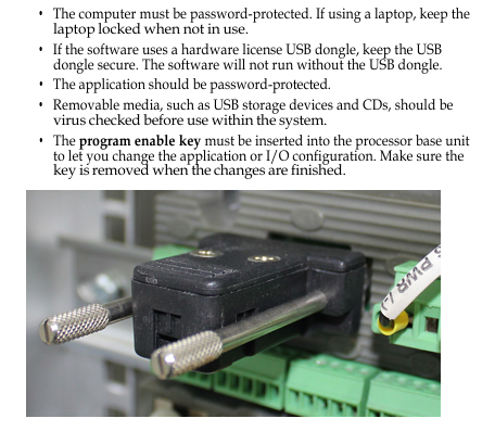
Program Security: The application requires password protection, and the controller needs to insert the "Program Enable Key" to modify the configuration; It is prohibited to force I/O points during operation, and it is recommended to use the program's "override" logic for maintenance.
Supporting documents and resources
1. Key related documents
Document Name Usage Description
AADvance Controller System Build Manual (ICSTT-RM448) System Assembly, Startup, and Operation Verification
AADvance PFH and PFDavg Data (ICSTT-RM449) Fault Probability (PFH/PFDavg) Data and Calculation Example
AADvance Troubleshooting and Maintenance Manual (ICSTT-RM406) System Maintenance, Troubleshooting, and Repair
2. Support channels
Technical support: Get help through rok.auto/support, register an account to subscribe to product security notifications.
Document download: Download the latest manuals and firmware from Rockwell Literature Library (rok.auto/iterative) or Product Compatibility and Download Center (rok.auto/pcdc).
Key Terminology (Glossary Simplified)
SIL (Safety Integrity Level): Safety Integrity Level, levels 1-4, with SIL 3 being the highest level supported by the manual.
PST (Process Safety Time): The maximum time for triggering a hazardous event when a hazardous state exists and there is no protection. The controller defaults to PST=2500ms and needs to be adjusted based on sensor/actuator delay.
MTTR (Mean Time To Repair): The average time to repair, during which faulty modules need to be replaced to maintain SIL.
1oo2D/2oo3D: Fault tolerant configuration, 1oo2D (2 out of 1 with diagnosis), 2oo3D (3 out of 2 with diagnosis).
- OMRON
- ABB
- General Electric
- EMERSON
- Honeywell
- HIMA
- ALSTOM
- Rolls-Royce
- MOTOROLA
- Rockwell
- Siemens
- Woodward
- YOKOGAWA
- FOXBORO
- KOLLMORGEN
- MOOG
- KB
- YAMAHA
- BENDER
- TEKTRONIX
- Westinghouse
- AMAT
- AB
- XYCOM
- Yaskawa
- B&R
- Schneider
- KONGSBERG
- NI
- WATLOW
- ProSoft
- SEW
- ADVANCED
- Reliance
- TRICONEX
- METSO
- MAN
- Advantest
- STUDER
- DANAHER MOTION
- Bently
- Galil
- EATON
- MOLEX
- DEIF
- B&W
- ZYGO
- Aerotech
- DANFOSS
- Beijer
- Moxa
- Rexroth
- Johnson
- WAGO
- TOSHIBA
- BMCM
- SMC
- HITACHI
- HIRSCHMANN
- Application field
- XP POWER
- CTI
- TRICON
- STOBER
- Thinklogical
- Horner Automation
- Meggitt
- Fanuc
- Baldor
- SHINKAWA
- Other Brands
- UniOP
- KUKA
- Iba
- Beckhoff
-
 Basler Electric DECS-200-1L Digital Excitation Control System
 -
 Basler DECS125-15-B2C1 Excitation Control
 -
 Basler 9507900205 SSR Retrofit Voltage Regulator
 -
 Basler BE2000E Digital Voltage Regulator
 -
 Basler BE1-GPS Generator Protection System
 -
 Basler DECS-250-CN1CN1N Digital Excitation Control
 -
 Basler DGC-2020 Genset Controller
 -
 Basler BE1-81O UT3ED1LA7N0F Frequency Relay (Variant)
 -
 Basler BE1-81O UT3EE1YA9S0F Frequency Relay (Variant)
 -
 Basler BE1-81O Over/Under Frequency Relay
 -
 Basler DECS125-15 Digital Excitation Control
 -
 Basler Electric BE1-951 Overcurrent Protection System
 -
 Basler Electric BE1-700V Digital Protective Relay
 -
 Basler Electric APR63-5 Automatic Voltage Regulator
 -
 Basler Electric BE1-851 Overcurrent Protection System
 -
 Basler Electric DECS-250-LN1SN1N Excitation Control
 -
 Basler Electric BE1-87T Transformer Differential Relay
 -
 Basler Electric DECS-200-1L Excitation Control System
 -
 Basler Electric 9310300100 DECS-300 Excitation Control
 -
 Basler Electric SSE-N 125-4.5KW Shunt Exciter Regulator
 -
 Basler Electric DGC-2020HD-5NS1DNSBA Genset Controller
 -
Basler Electric BE1-81-O/UT3EE1JB7N1F Frequency Relay
-
 Basler Electric BE1-81T1EE1WA0N1F Frequency Relay
 -
 Basler Electric BE1-25M1EA6PN5R1F Sync-Check Relay
 -
 Basler Electric BE1-GPS Generator Protection System
 -
Basler Electric DECS-250-LN1SN1N Excitation Control Rev V
-
 Basler Electric DECS-250-CN2CN1N Excitation Control
 -
 Basler Electric BE1-50/51B-207 Overcurrent Relay
 -
Basler Electric DECS-300-C0N0 Excitation Control System
-
Basler Electric DECS-200 Digital Excitation Control System
-
Basler Electric DECS-250-LN1CN1N Excitation Unit
-
Basler Electric DECS-250 LN2SA1D Excitation Unit Specs
-
Basler Electric BE1-87T Transformer Relay Review
-
Basler Electric BE1-11 Protection System
-
Basler Electric BE1-GPS100-E4N1H1N Protection System
-
 Allen-Bradley 442G-MABH-R Safety Module
 -
 Beckhoff CX1030-0111 PLC Assembly Profile
 -
 FANUC IC693CPU364 PLC Module
 -
 Orange Denmark Type 200816 220 PLC Specs
 -
 OMRON C200H-SNT31 Sysmac PLC Module
 -
 Allen Bradley 20AB022A3AYNANC0 PowerFlex 70
 -
 OMRON C200HW-PCU01 Position Control Unit
 -
 ABB AO845A-eA Analog Output Module
 -
 OMRON CJ1M-CPU22 CPU Unit
 -
 Allen Bradley 100-E265ED11 Contactor
 -
 Honeywell 51304511-100 Interface Module
 -
 SOLEXY BXF3S0101N0018 Gateway Module
 -
 OMRON CJ2H-CPU65 CPU Unit
 -
 Automation Direct GS2-45P0 AC Drive
 -
 M68-2000 2-Axis Motion CNC Controller
 -
 OMRON CJ1M-CPU11 V3.0 PLC CPU Unit
 -
 OMRON CJ1W-NC413 4-Axis Positioning Controller
 -
 OMRON 3G2A3-PRO16 Programming Console HMI
 -
 Siemens 3VT8440-2AA04-2GA2 Molded Case Circuit Breaker
 -
 Siemens 3RT5045 Contactor Series
 -
 OMRON C200HS-CPU01-E SYSMAC PLC Controller
 -
 OMRON C500-NC103-E Positioning Control Unit
 -
 OMRON CJ1W-TC001 Temperature Control Unit
 -
 OMRON NJ301-1100 NJ-PA3001 PLC System EtherCAT
 -
 Pilz 773100 M1P Safety Relay Base Unit
 -
 Siemens SINUMERIK 840D SL NCU 720.3B with PLC 317-3 PN/DP
 -
 Siemens 6AV6618-7GD01-3AB0 HMI Panel
 -
 OMRON F150-C15E-3 Vision Mate Controller PLC Overview
 -
 Mitsubishi MELSEC A Series PLC System A63P A3ACPU A616AD A68RD3
 -
 M68-2000 2 Axis Motion Controller SCE SERVO CNC
 -
 OMRON FZ-S2M PLC Camera Vision System
 -
 VISOLUX SLVA-4K PLC Module from Elektronik GmbH
 -
 OMRON CJ1M-CPU23 V2.0 PLC CPU Unit
 -
 ABB AI86-16CHF PCB Card 5761751-9 B Specifications
 -
 Allen-Bradley 100-D140ZJ22L Contactor Overview
 -
 Merlin Gerin PB80 PLC Rack
 -
 WEIR WE203 Power Supply PLC
 -
 OMRON NX-TS3102 Temperature Input Unit
 -
 Siemens 6ES7146-6FF00-0AB0 I/O Module
 -
 Fanuc A16B-3300-0057 Circuit Board
 -
 OMRON CJ1W-IDP01 Input Module
 -
 Siemens 6FX2007-1AD13 Handheld Unit
 -
 Gems EM54 PLC Module PCB
 -
 Beckhoff CX2030-0121 Embedded PC CPU
 -
 OMRON NJ301-1100 Machine Automation Controller
 -
 Biesse Rover CNI PLC 2153 030 7146.30 Numerical Control Module
 -
 OMRON CJ1W DA08V Analog Output Module
 -
 OMRON CS1D ETN21D Ethernet Module
 -
 Allen Bradley 1768 L43 CompactLogix Controller
 -
 Schneider TWDLMDA40DTK Twido PLC Module
 -
 Mitsubishi NZ2EX2B 60AD4 Analog Input Module
 -
 OMRON NS8 TV00B V2 Touch Display Panel
 -
 Mitsubishi AY71 CMOS TTL Output Module
 -
 OMRON C500 CPU11 E Processor Module
 -
 OMRON CJ1W PTS51 Temperature Input Module
 -
 Siemens 6SL3100-1DE22-0AA1 600V DC Supply
 -
 OMRON CJ1M-CPU23 PLC CPU 9‑Pin Serial
 -
 Schlumberger IMT4N 24‑250VAC 48‑230VAC PLC Timer
 -
 OMRON CJ1M-CPU22 PLC CPU Unit V2.0
 -
 Allen‑Bradley 2711P-B7C6D2 Touch Screen PanelView
 -
 ADSP-2181KST-160 Analog Devices DSP IC Specs
 -
 Schneider LC1F400 400A Contactor Specifications
 -
 Yaskawa SGDH-10DE-OY 1kW 400V Servo Drive
 -
 Schneider TM262L10MESE8T M262 PLC 5ns Inst
 -
 Mitsubishi AA104VJ05 10.4in LCD Panel Specs
 -
 Allen Bradley 1761-L32BWA MicroLogix 1000 PLC
 -
 Siemens 6ES7431-7KF00-0AB0 Analog Input Module
 -
 Allen Bradley 1769-OB16 Output Module
 -
 Siemens 6ES7131-1BL12-0XB0 Input Module
 -
 Beckhoff EP7041-3002 EtherCAT Box Module
 -
 Siemens RK7243-2AA30-0XB0 Communication Module
 -
 Siemens 4AM5742-8DD40-0FA0 Transformer
 -
 Siemens 3TK2834-1BB40 Safety Relay
 -
 Brother BAS 311 Sewing Machine Circuit Board
 -
Yaskawa SGDH-10DE-OY Servo Driver
-
 OMRON C60H C6DR DE V1 Sysmac PLC
 -
 MITSUBISHI ELECTRIC A2ACPU21 S1 CPU Module
 -
 ABB BAILEY INNPM12 Network Process Module
 -
 HONEYWELL 620 0073C IPC PLC Module
 -
 Mitsubishi 15050 PR02B PLC Circuit Board
 -
 SIEMENS 6SY7000 0AC37 Drive Control Module
 -
 OMRON TJ2 ECT16 Traxial EtherCAT Controller
 -
 GE Fanuc IC698PSD300D Power Supply Module
 -
 Texas Instruments Series 505 16 Position Base
 -
 OMRON YASKAWA SGDH 10DE OY Servo Drive
 -
 Allen‑Bradley 440G-MT Safety Interlock Switch Specs
 -
 Rubycon PD27A 24V 8A Power Supply Module
 -
 SK-H1-GDB1-F11D PLC Gate Driver Board Kit
 -
 VIPA 441-4UA14 451-4UA14 PLC Module Rack
 -
 Mitsubishi FX5U-80MT ESS PLC Controller Specs
 -
 Mitsubishi Q64TCRTN Temperature PLC Module
 -
 GE 1C31170G Rev10 PLC Circuit Board Module
 -
 Schneider TWDLMDA40DTK PLC Controller Module


