ABB Relion ® 615 series RED615 line differential protection and control device
Integrated protection function: with "line differential protection" as the core main protection, while integrating backup protection such as overcurrent, ground fault, circuit breaker failure, etc., to meet the requirements of modular protection;
Standardized communication: Deeply compliant with the IEC 61850 standard, supporting GOOSE messages (transmission delay ≤ 3ms), IEC 60870-5-103, Modbus ®、 DNP3 and other protocols, adapted for interconnection of substation automation systems;
Flexible configuration capability: Provides 3 standard configuration solutions, supports customizing signal logic through PCM600 tool, and adapts to different grounding methods (isolated neutral, resistance grounding, compensation grounding, direct grounding) of the power grid;
Full lifecycle support: Equipped with a complete documentation system (engineering, installation, debugging, operation and maintenance manuals), supporting local (LHMI) and remote (WHMI) operations, simplifying engineering and maintenance processes.
ABB Relion ® 615 series RED615 line differential protection and control device
Product basic positioning and core features
RED615 is ABB Relion ® The intelligent electronic device (IED) for line differential protection and control under the 615 series is designed specifically for public utilities and industrial power systems. Its core application is the protection and control of overhead lines and cable feeders, and it is suitable for ring and mesh power grids with or without distributed generation. Its core characteristics can be summarized as:
Integrated protection function: with "line differential protection" as the core main protection, while integrating backup protection such as overcurrent, ground fault, circuit breaker failure, etc., to meet the requirements of modular protection;
Standardized communication: Deeply compliant with the IEC 61850 standard, supporting GOOSE messages (transmission delay ≤ 3ms), IEC 60870-5-103, Modbus ®、 DNP3 and other protocols, adapted for interconnection of substation automation systems;
Flexible configuration capability: Provides 3 standard configuration solutions, supports customizing signal logic through PCM600 tool, and adapts to different grounding methods (isolated neutral, resistance grounding, compensation grounding, direct grounding) of the power grid;
Full lifecycle support: Equipped with a complete documentation system (engineering, installation, debugging, operation and maintenance manuals), supporting local (LHMI) and remote (WHMI) operations, simplifying engineering and maintenance processes.

Document and symbol specifications
(1) Document system and audience
Document positioning: This document is the "Application Manual", focusing on functional application scenarios and parameter setting guidelines. It needs to be used in conjunction with other manuals (such as the "Engineering Manual" for tool operation and the "Installation Manual" for physical installation);
Target audience: Protection and control engineers with knowledge of power engineering and communication protocols, responsible for equipment planning, preliminary engineering, and on-site debugging;
Version history: The current version is version B (released in July 2009), corresponding to product version 2.0. Compared to version A (October 2008), it has added support for DNP3 protocol, standard configuration B/C, and WHMI disturbance record upload function.
(2) Security and document symbols
Symbol Type Meaning Application Scenarios
The electrical warning icon poses a risk of electric shock and involves chapters on power wiring and terminal operation
Warning icons may pose a chain risk of personal injury caused by equipment failure, such as power grid accidents due to protection failure
Please note that icons may cause device damage, software abnormalities, parameter configuration errors, improper wiring, and other scenarios
Information icon key operation prompt function activation conditions and default parameter description
Suggestions for optimizing icon engineering, such as CT selection techniques and communication networking solutions
(3) Functional coding specification
The functional identification adopts a combination of "IEC 61850 name+IEC symbol+IEC-ANSI number", for example:
Line differential protection: LNPLDF1 (IEC 61850), 3dI>L (IEC symbol), 87L (ANSI number);
Directional grounding fault protection: DEFLPDEF1 (IEC 61850), I ₀>→ (1) (IEC symbol), 67N-1 (1) (ANSI number).
Product hardware and operating interface
(1) Hardware structure
The RED615 hardware consists of a "plug-in unit+chassis", and the core plug-in modules and functions are as follows:
Plug in module slot ID core function key parameters
Auxiliary power supply/BO module X100 provides auxiliary power supply, output trip/signal contact power input: 48-250V DC/100-240V AC; Including 2 sets of PO contacts and 1 set of SO contacts
Binary I/O module X110 binary input/output with 8 BI and 4 SO contacts
Analog input/BI module X120 collects current/voltage signals, expands BI 3-channel phase current (1/5A), 1-channel zero sequence current (1/5A or 0.2/1A), and 1-channel zero sequence voltage (configuration B exclusive)
Optional BIO module X130 expansion I/O with 6 BI and 3 SO contacts
Communication module X000 protocol communication supports Ethernet (100BASE-TX), RS-485, and fiber optic (ST interface)
(2) Operation interface
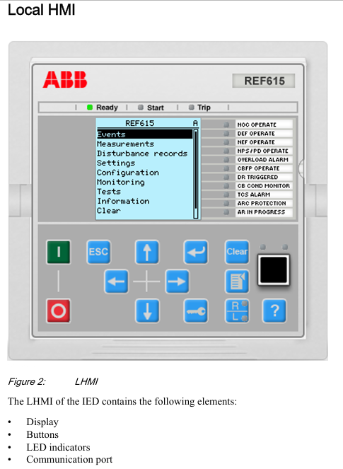
Local HMI (LHMI)
Display unit: LCD supports two character sizes (small characters: 5 rows x 20 columns; large characters: 4 rows x 8 columns), divided into four display areas: "title, icon, content, and scrollbar";
LED indicator lights: 3 fixed protection lights (Ready/Start/Trip)+11 programmable alarm lights (such as differential protection action, CT fault);
Key functions: navigation key (switching menu), control key (circuit breaker opening and closing), function key (alarm confirmation, reset, local/remote switching).
Web HMI(WHMI)
Access method: accessed through IE 7.0+browser, disabled by default, requires manual activation;
Core functions: parameter configuration, real-time measurement value viewing, disturbance record download, phasor diagram display, menu structure consistent with LHMI;
- ABB
- General Electric
- EMERSON
- Honeywell
- HIMA
- ALSTOM
- Rolls-Royce
- MOTOROLA
- Rockwell
- Siemens
- Woodward
- YOKOGAWA
- FOXBORO
- KOLLMORGEN
- MOOG
- KB
- YAMAHA
- BENDER
- TEKTRONIX
- Westinghouse
- AMAT
- AB
- XYCOM
- Yaskawa
- B&R
- Schneider
- Kongsberg
- NI
- WATLOW
- ProSoft
- SEW
- ADVANCED
- Reliance
- TRICONEX
- METSO
- MAN
- Advantest
- STUDER
- KONGSBERG
- DANAHER MOTION
- Bently
- Galil
- EATON
- MOLEX
- DEIF
- B&W
- ZYGO
- Aerotech
- DANFOSS
- Beijer
- Moxa
- Rexroth
- Johnson
- WAGO
- TOSHIBA
- BMCM
- SMC
- HITACHI
- HIRSCHMANN
- Application field
- XP POWER
- CTI
- TRICON
- STOBER
- Thinklogical
- Horner Automation
- Meggitt
- Fanuc
- Baldor
- SHINKAWA
- Other Brands


