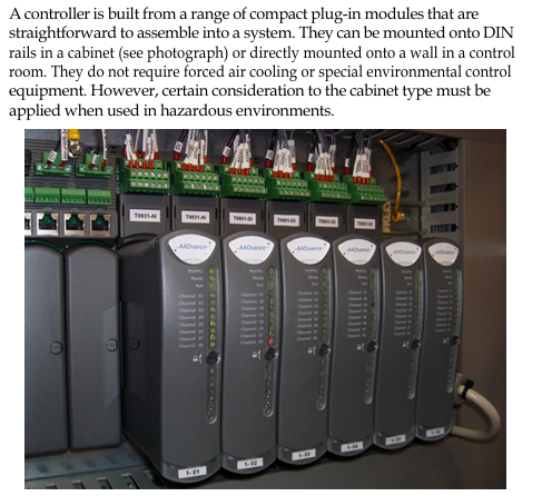
Rockwell Automation ICS AADvance Controller
Core objective: Define SIF safety application standards (mandatory) and recommendations to ensure that the system meets and maintains the required Safety Integrity Level (SIL), with a maximum support for SIL 3.
Rockwell Automation ICS AADvance Controller
Basic Information and Usage Standards
1. Scope of application and core objectives
Applicable products: AADvance controller series (T9100/T9110 processor modules, T9401/2 digital input modules, etc.) and supporting software (AADvance Workbench 1.4/2.1, AADvance Robust SIS Workstation 2.00), supporting system version 2.011.
Core objective: Define SIF safety application standards (mandatory) and recommendations to ensure that the system meets and maintains the required Safety Integrity Level (SIL), with a maximum support for SIL 3.
2. Key usage requirements
Personnel qualifications: Installation, configuration, operation and maintenance operations must be carried out by professionally trained personnel who are familiar with relevant regulations (such as IEC 61508, NFPA series standards).
Responsibility statement: If the device is used in a manner that does not comply with the manufacturer's regulations, the protective function of the device may become ineffective; Rockwell is not responsible for indirect/consequential damages, and the examples in the manual are for illustration only and do not represent actual application guarantees.
System core features and authentication
1. Core functions and security design
Application scenarios: Suitable for safety critical scenarios such as emergency shutdown (ESD), fire and gas detection, rotating machinery control, burner management, etc., while supporting non safety but business critical control requirements.
Security Capability:
Both fail safe and fault tolerant architectures are supported, and fault tolerance can be realized through two module (1oo2D) or three module (2oo3D) configurations.
Built in comprehensive diagnostic function, capable of detecting hardware/software faults. The faulty module needs to be replaced within the mean time to repair (MTTR) to avoid a decrease in SIL level.
Supports two configurations: "Power Loss Trip (DTT)" and "Power On Action (ETA)", and the number of modules needs to be selected based on SIL level and demand rate (high/low) (see Table 1).
2. Module configuration and SIL compliance requirements
Minimum module configuration for different application scenarios (simplified version of Table 1):
Application type, number of input modules, number of processor modules, number of output modules
SIL 2/3, Low/high demand, DTT 1 2 1
SIL 2, High demand, ETA 2 2 2
SIL 3, High demand, ETA 2 2 2
Note: The single channel digital output module includes a series switch. The DTT scenario supports SIL 3, while the ETA scenario only supports SIL 2; There are no three module output configuration options.
3. International certification and compliance standards
Functional safety certification: Compliant with IEC 61508 SIL 3, certified by an independent certification body.
Hazardous environment certification:
North America: Class I, Division 2, Groups A-D (UL 61010-2-201, CSA C22.2 standard).
Europe/UK: ATEX (DEMKO 11 ATEX 1129711X, Ex ec IIC T4 Gc), UKCA (UL24UKEX2993).
International: IECEx (certificate number IECEx UL 12.0032X).
Other compliance: Complies with industry standards such as EN 50156 (furnace control), EN 54 (fire alarm), NFPA 85/86/87 (boilers/ovens/fluid heaters), etc.

Safety lifecycle and management system
1. Safety lifecycle stages
The full lifecycle defined by IEC 61508 must be followed, with core stages including:
Scope definition: Clearly define system boundaries, interfaces (with processes/third-party equipment), and environmental requirements (such as temperature and power).
Hazard and Risk Analysis: Identify hazardous events, trigger sequences, and risk levels as inputs for safety requirements.
System Design and Engineering: Divide system architecture, define security requirement levels for each component, and refine hardware/software design.
Integration and Verification: The application is integrated with the controller to test and verify whether SIF meets SIL requirements (such as response time and fault handling).
Operation and Maintenance: Develop an operation/maintenance plan to ensure the SIL level is maintained during operation; Changes must be strictly controlled, and suspensions must follow safety procedures.
2. Requirements for Safety Management System
Policy and Planning: Functional safety policies need to be developed to clarify measures, responsibilities, and record management (including change control) for each stage of the lifecycle.
Personnel capability: Personnel qualifications need to be evaluated, including engineering experience, functional safety knowledge, regulatory familiarity, etc. Higher qualification requirements are required for high-risk scenarios.
Functional Safety Assessment (FSA): Led by senior personnel independent of the project, it reviews whether the entire lifecycle work meets the requirements.
System Architecture Design (SIL 2/3)
1. SIL 2 architecture
Fault safety architecture: single input (1oo1D), dual processor (1oo1D degraded), single output (1oo1D), triggering a safe state in case of a fault.
Fault tolerant input architecture: dual/triple input (1oo2D/2oo3D), dual processors, single output. When a single input module fails, it will operate in a degraded state while still maintaining safety functions.
- ABB
- General Electric
- EMERSON
- Honeywell
- HIMA
- ALSTOM
- Rolls-Royce
- MOTOROLA
- Rockwell
- Siemens
- Woodward
- YOKOGAWA
- FOXBORO
- KOLLMORGEN
- MOOG
- KB
- YAMAHA
- BENDER
- TEKTRONIX
- Westinghouse
- AMAT
- AB
- XYCOM
- Yaskawa
- B&R
- Schneider
- Kongsberg
- NI
- WATLOW
- ProSoft
- SEW
- ADVANCED
- Reliance
- TRICONEX
- METSO
- MAN
- Advantest
- STUDER
- KONGSBERG
- DANAHER MOTION
- Bently
- Galil
- EATON
- MOLEX
- DEIF
- B&W
- ZYGO
- Aerotech
- DANFOSS
- Beijer
- Moxa
- Rexroth
- Johnson
- WAGO
- TOSHIBA
- BMCM
- SMC
- HITACHI
- HIRSCHMANN
- Application field
- XP POWER
- CTI
- TRICON
- STOBER
- Thinklogical
- Horner Automation
- Meggitt
- Fanuc
- Baldor
- SHINKAWA
- Other Brands


