
ProSoft Technology ILX56-PBM PROFIBUS DPV1 Master/Slave Module
ProSoft Technology ILX56-PBM PROFIBUS DPV1 Master/Slave Module
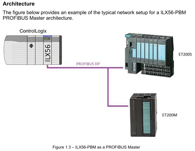
ILX56-PBM is an adaptation of ControlLogix launched by ProSoft Technology ® The PROFIBUS DPV1 master/slave module of the platform enables efficient data exchange between the ControlLogix controller and PROFIBUS DP devices, supports DPV0 cyclic data exchange, DPV1 non cyclic message and alarm functions, and has redundant deployment, flexible configuration, and comprehensive diagnostic capabilities. It is suitable for applications that require the integration of PROFIBUS bus and ControlLogix system in industrial automation, process control, and other scenarios.
Core functions and architecture
1. Work mode and core competencies
ILX56-PBM supports bidirectional switching between master and slave modes, with core functionality covering the full protocol stack of PROFIBUS DPV0/DPV1
Master mode:
Manage up to 125 PROFIBUS DP slave devices, supporting DPV0 cyclic data exchange (up to 5000 bytes of data), DPV1 Class 1 (MS1, only communicates with configured slave devices), and Class 2 (MS2, concurrent communication with multiple master stations) non cyclic messages.
Support DPV1 alarm collection (such as diagnostic alarms and process alarms), which can read device alarm and diagnostic information through the ControlLogix controller, and support automatic device discovery and station address modification.
From mode (Slave):
It can simulate up to 10 PROFIBUS DP slave devices, support DPV0 cyclic data exchange and DPV1 Class 1 messages, and each analog slave device can be configured with independent I/O mapping and alarm triggering mechanisms.
Supports communication with third-party PROFIBUS master stations, automatically adapts data formats to ControlLogix user-defined data types (UDT), and ensures alignment of 16/32-bit data structures.
2. Hardware architecture and interfaces
Physical interface:
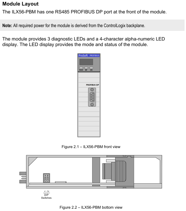
PROFIBUS DP port: RS485 standard DB9 female head, supports+5VDC terminal resistor power supply, pins 3 (RxD/TxD-P) and 8 (RxD/TxD-N) are differential data pins, and pin 5 is reference ground.
Expansion interface: onboard SD card slot (supporting FAT32 format for firmware backup and configuration recovery), 2 DIP switches (SW1: forced safe mode for firmware repair); SW2: Configuration lock to prevent accidental modifications.
Indicator lights and display: 3 diagnostic LEDs (RUN/FB/OK)+4-character alphanumeric display screen, real-time display module mode (such as "MASTER" and "SLAVE"), operating status (such as "OPERATE" and "OFFLINE"), and fault information (such as "Bus Fault" and "Duplicate Station").
Configuration and deployment process
1. Configuration tools and preliminary preparations
Core tool: ProSoft PLX50 Configuration Utility (available for download from the official website) needs to be installed for module parameter configuration, GSD file management, device addition, and configuration download; Studio 5000 requires the installation of Add On Profile (AOP, v21 and above versions, v20 and below require the use of the universal 1756 module configuration file).
GSD file management: PROFIBUS devices need to be imported into PLX50 tool through GSD files, supporting GSD directory export/import, and can batch add third-party PROFIBUS devices (such as Siemens ET200M, Schneider ATV frequency converter, etc.).
2. Key configuration steps
(1) Basic parameter configuration
Main mode configuration:
Set the PROFIBUS station address (TS, 0-126, which should not conflict with the slave devices), the highest station address (HSA, it is recommended to set it as the actual maximum slave address to optimize performance), and the baud rate (9.6Kbps-12Mbps, which should match all slave devices).
Configure DPV1 parameters: Enable Class 1/Class 2 messages, enable alarms (such as Pull Plug alarms, process alarms), and set timeout time (such as DPV1 request timeout of 2000ms).
From mode configuration:
Simulate the number of slave devices and station addresses, and each slave device needs to be configured with DPV0 data length, DPV1 object (Slot/Index mapping), and alarm triggering conditions (such as Alarm Trigger tag level switching triggering alarms).
(2) ControlLogix Mapping
Generate Logix L5X files using the PLX50 tool, including UDT (such as master status UDT, slave device data UDT), mapping programs, and controller labels. After importing into Studio 5000, automatically associate module input/output mapping areas.
Mapping rule: Input data (from PROFIBUS devices to ControlLogix) and output data (from ControlLogix to PROFIBUS devices) are packaged into byte arrays and automatically parsed into structured labels (such as MyILX56PBM.ET200M.Input. Data) through generated subroutines.
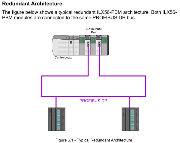
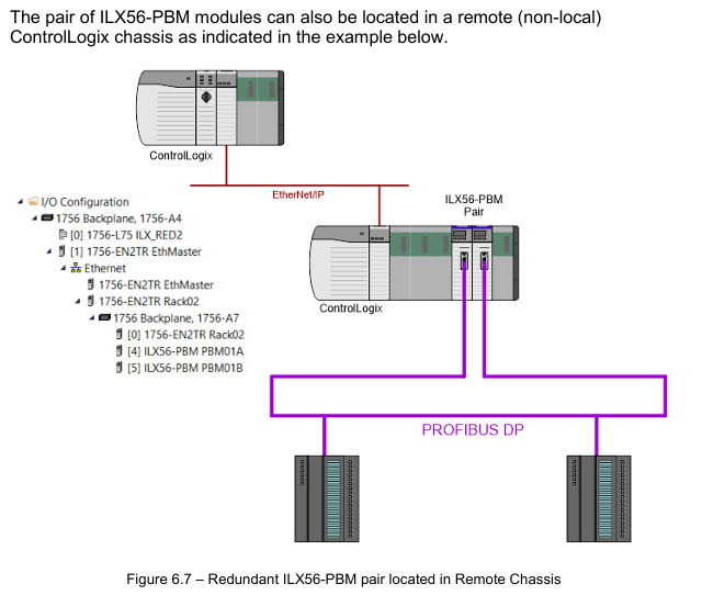
(3) Redundant deployment (exclusive to main mode)
Redundant architecture: Two ILX56-PBM modules share the same PROFIBUS bus, with identical configurations and support for "one master, one backup" switching. The backup machine automatically takes over the main station role by monitoring bus activity (PROFIBUS Inactive Time parameter, default 22ms).
Key parameters:
Profibus Inactive Time: The inactive time of the bus that determines the failure of the main station by the backup machine should be set as "10ms+2 x maximum packet transmission time".
Switch Timeout: The timeout for confirming the primary/backup switch should be set to "Max (1000ms, 4x module RPI)" to avoid switch interruption.
Data interaction and operation
1. Data exchange type
(1) DPV0 cyclic data exchange
Main mode: Interact data with slave devices according to a preset cycle (configurable, minimum 4ms). The input/output data length of each slave device is automatically identified through GSD files, supporting byte/word order exchange (such as AA BB CC DD → BB AA DD CC). In case of communication failure, data can be configured to be forcibly cleared to zero.
From mode: Simulate receiving loop data requests from the PROFIBUS master station, forward ControlLogix output label data to the master station, and write the data issued by the master station to the ControlLogix input label, supporting "Data Exchange Active" status feedback (DataExchange Active label).
(2) DPV1 non cyclic message
Class 1 (MS1): Interacts only with slave devices that have established loop communication in master mode, used for parameter reading and writing (such as modifying slave device range, reading diagnostic registers). The slave address, Slot number, Index number, and data length need to be specified, and the timeout time can be configured (default 4000ms).
Class 2 (MS2): Supports concurrent communication with multiple master stations, requires establishing a connection through "Initialize", obtaining the connection reference number, and performing read and write operations. After the communication ends, a "Abort" message is sent to release resources, suitable for device debugging and parameter configuration.
(3) Alarm and Diagnosis
Alarm collection: Automatically monitor DPV1 alarms from the slave device in main mode, indicating the alarm status through the DeviceAlarmPending tag. Alarm data (such as alarm type, Slot number, detailed description) can be extracted through CIP messages (service code 0x51).
Diagnostic information: Supports standard diagnostics (such as device unresponsive, data length mismatch) and extended diagnostics (device specific diagnostics based on GSD file parsing, such as module failures, wiring errors), which can be viewed or exported in real-time through the PLX50 tool.
Diagnosis and maintenance
1. Status monitoring and LED indication
Meaning of LED light status (main mode) Meaning of status (slave mode)
RUN often red: PROFIBUS STOP mode; Flash green: CLEAR mode; Evergreen: Operational mode; Off: OFFLINE mode is always off (no RUN status indication from mode)
FB flashing red: from device error; Always red: Bus fault (such as cable disconnection); Extinguish: Normal flashing red: Simulate device error; Constant red: Bus communication failure; Extinguish: Normal
OK often red: Hardware malfunction/firmware damage; Flashing green: No configuration; Evergreen: configured normally and running in the same main mode
Display screen: display mode ("MASTER"/"SLAVE"), operating status ("OPERATE"/"STOP"), fault code (such as "Duplicate" indicating station address conflict).
2. Tool based diagnostic function
PROFIBUS packet capture: The PLX50 tool supports real-time capture of bus packets, displaying frame types (SD2/SD4), source/destination addresses, data length, and raw data. It can filter specific station addresses or frame types (such as Token frames, SRD data frames) to troubleshoot communication anomalies.
Event log: The module has built-in non-volatile memory to store event logs (such as power on, configuration download, and failover), which can be exported as text files using the PLX50 tool, including timestamps, event types, and detailed descriptions.
Online status monitoring: The PLX50 tool provides a "Live List" to display the real-time online status of all devices on the bus (online/offline, data exchange in progress/not yet exchanged), and the "Discovered Nodes" tab can view device manufacturer, model, and GSD file information.
Technical specifications and compatibility
1. Hardware and environmental specifications
Category parameters
Power supply from ControlLogix backplane: 5VDC 450mA, 24Vdc 2mA
Working temperature -20 ° C~+70 ° C (operation), -40 ° C~+85 ° C (storage)
Electromagnetic compatibility (EMC) emission: IEC 61000-6-4; Immunity: EN 61000-4-2 (ESD), EN 61000-4-3 (radiated immunity)
PROFIBUS supports baud rates of 9.6Kbps~12Mbps, maximum bus lengths of 1200m (9.6Kbps) and 100m (12Mbps), and supports repeater expansion
Certified CE, UL (94V-0 flame retardant), ATEX (II 3G Ex ec IIC T4 Gc), IECEx (same as ATEX)
2. Software compatibility
ControlLogix platform: Supports ControlLogix 1756 series controllers, Studio 5000 v21 and above (AOP required), v20 and below require the use of a universal module configuration file.
Operating system: PLX50 Configuration Utility supports Windows 10/11 (64 bit), firmware upgrade requires the use of SD card or PLX50 tool's DeviceFlash function.
Third party devices: compatible with slave devices that comply with the PROFIBUS DP V0/V1 standard (such as Siemens ET200 series, Schneider Lexium drivers), requiring the import of corresponding GSD files.
Configuration and Deployment Tools
1. PLX50 Configuration Utility
Core functions: Project management (create/copy/export), GSD file management (add/delete/import directory), module parameter configuration (master/slave mode, PROFIBUS parameters, Logix connection), configuration download/upload, device discovery and diagnosis.
Key operations:
Generate Logix L5X file: Automatically map PROFIBUS data to ControlLogix tags, including UDT and subroutines.
SD card configuration backup: Save the current configuration to the SD card for quick recovery during module replacement.
2. Studio 5000 Integration
AOP installation: After importing the Add On Profile of ILX56-PBM, modules can be directly added in the I/O configuration to automatically generate Module Defined Data Types.
Tag mapping: By importing the L5X file generated by PLX50, controller tags (such as Local: 1: MasterStatus master status tag, MyILX56PBM-ET200M.Input slave device data tag) are automatically created, supporting online monitoring and forced operations.
Ordering and Support
Typical models and accessories
Core module: ILX56-PBM (basic model, including master/slave mode function).
Supporting accessories:
SD card: used for firmware and configuration backup, requiring FAT32 format (recommended 4GB or above).
Terminal resistor: The end of the PROFIBUS bus needs to be connected to a 220 Ω terminal resistor (pins 3-8 of module DB9 can be powered by+5V).
Transfer cable: PROFIBUS bus extension cable (must comply with PROFIBUS standard, impedance 135-165 Ω, electrical)
Application scenarios
ILX56-PBM is suitable for scenarios where PROFIBUS DP devices (such as sensors, drivers, I/O modules) need to be connected to the ControlLogix system. Typical applications include:
Industrial automation: In semiconductor equipment and automated testing equipment (ATE), high-precision timing control is achieved through the main mode management of PROFIBUS I/O modules.
Process control: In petrochemical and water treatment systems, real-time monitoring of valve and transmitter status is achieved through DPV1 alarm and diagnostic functions to ensure process safety.
System integration: Third party PROFIBUS master stations (such as Siemens S7-300/400) interact with the ControlLogix system for data exchange, achieving bidirectional data forwarding through slave mode to avoid protocol conversion bottlenecks.
- OMRON
- ABB
- General Electric
- EMERSON
- Honeywell
- HIMA
- ALSTOM
- Rolls-Royce
- MOTOROLA
- Rockwell
- Siemens
- Woodward
- YOKOGAWA
- FOXBORO
- KOLLMORGEN
- MOOG
- KB
- YAMAHA
- BENDER
- TEKTRONIX
- Westinghouse
- AMAT
- AB
- XYCOM
- Yaskawa
- B&R
- Schneider
- KONGSBERG
- NI
- WATLOW
- ProSoft
- SEW
- ADVANCED
- Reliance
- TRICONEX
- METSO
- MAN
- Advantest
- STUDER
- DANAHER MOTION
- Bently
- Galil
- EATON
- MOLEX
- DEIF
- B&W
- ZYGO
- Aerotech
- DANFOSS
- Beijer
- Moxa
- Rexroth
- Johnson
- WAGO
- TOSHIBA
- BMCM
- SMC
- HITACHI
- HIRSCHMANN
- Application field
- XP POWER
- CTI
- TRICON
- STOBER
- Thinklogical
- Horner Automation
- Meggitt
- Fanuc
- Baldor
- SHINKAWA
- Other Brands
- UniOP
- KUKA
- Iba
- Beckhoff
-
 OMRON B7AM-8B16 I/O Terminal Block
 -
 Fanuc A06B-6110-H026 Power Supply Module
 -
 Schneider TSXETG3021 Ethernet Gateway
 -
 OMRON CS1W-CLK21-V1 Controller Link Unit
 -
 NP1W6406T-Z704 PLC I/O Module
 -
 OMRON CJ1W-DA08C Analog Output Module
 -
 Yaskawa 3G3HV-A4022-CE AC Drive
 -
 OMRON NB7W-TW01B CP1L-EL20DR-D Power Panel
 -
 OMRON C500-NC103-E Position Control Unit
 -
 Steag Hamatech PLC DCS Servo Control System
 -
 Siemens 6SN1123-1AA00-0DA1 Power Supply Module
 -
 GE IC693CHS391H CPU & AD693CMM301A PLC Module
 -
 Siemens 6FC5303-0AF23-1AA1 PLC Control Panel
 -
 Square D CM4000T PowerLogic Circuit Monitor J1 F16
 -
 Siemens 6FX5002-5DG10-1BA0 MOTION-CONNECT 500 Cable
 -
 Schmersal SRB324ST 101195504 Safety Relay 24V
 -
 Mitsubishi 15050-PR02A PLC Circuit Board Module
 -
 OMRON CQM1-AD041 Analog Input PLC Module
 -
 Beckhoff EL5042 EtherCAT PLC Terminal Module
 -
 OMRON C200HW-MC402-E Motion Control Unit
 -
 C36TC0UA1100 Industrial Temperature Controller
 -
 NL8048BC24 12 Industrial Control LCD Module
 -
 OMRON R88D Servo Drive and Motor System
 -
 OMRON CS1W CLK21 V1 Controller Link Module
 -
 OMRON YASKAWA R7M A20030 S1 D Servo Motor
 -
 SIEMENS 6AV2128 3KB06 0AX1 Unified Comfort Panel
 -
 Schneider Electric METSEPM8240 PowerLogic Meter
 -
 Advanced AMCI 1PLC 1 31F Programmable Limit Switch
 -
 ABB PM582 ETH Programmable Logic Processor
 -
 SIEMENS 6FC5110 0CB01 0AA0 CPU Control Board
 -
 Schleicher P03GS13A CPU Module
 -
 Siemens 6SN1123-1AA00-0BA1 Power Module
 -
 Mitsubishi A1S61PN Power Supply Module
 -
 Yaskawa CPS-IONB DC Power Supply Module
 -
 Siemens 6ES7215-2BD00 CPU 215-2
 -
 Mitsubishi A2ACPU MELSEC PLC System Kit
 -
 ProSoft 3150-MCM Communication Module
 -
 Mitsubishi OSE104ET Incremental Encoder
 -
 OMRON CJ1W-AD081-V1 Analog Input Module
 -
 Broadcom BCM5464A1KRB Quad Port Ethernet IC
 -
 Modicon M221-24IO TM221C24 PLC 24 PNP Transistor
 -
 Allen-Bradley 1321-3R160-B Line Reactor 3R160B
 -
 Beckhoff CX1020-0012 Embedded PLC Module Specs
 -
 Turck BL20-PF-24VDC-D Power Feed Module Specs
 -
 Siemens 6SY7000-0AC37 Power Supply Module
 -
 Yaskawa SGDH-10DE-OY 1kW 400V Servo Drive Specs
 -
 Omron 3G3SV-BB015-E 1.5kW 220V VFD Specs
 -
 Uni-Pro CPU91-PLC J 23.020167X Processor Module
 -
 PASABAN MTC-3044 PLC Rack Power Supply 4835-A
 -
 XYCOM 3015T Operator Interface Panel BIN4.4.4
 -
 OMRON CJ1W-MD261 Mixed I/O Module
 -
 Omron NJ301-1100 PLC CPU eCat EIP Specs
 -
 Omron F500-C15-ETN Vision System PLC Module
 -
 Modicon M241-24IO TM/T2UK PLC with Ethernet
 -
 SIXNET YS-800-001 RTU PLC Module
 -
 BEMAC UST-202-D Interface Board 1307D V08B2
 -
 Yaskawa JANCD-MMOIC-02 Drive Circuit Board
 -
 ABB 3BSE005028R1 SDCS-COM-1 Comm Board
 -
 Omron 3G3MX2-A4110 A4150 Inverter Drives Specs
 -
 KEYENCE CA-E100 PLC Module
 -
 GE IC693ALG223-GB Analog Input Module Specs
 -
 ABB BAILEY IMMFP01 Multi Function Processor System
 -
 SIEMENS 6FC5372 0AA00 0AA1 NCU 7202 Controller
 -
Modicon TM241CE4 40I O Transistor Programmable Controller
-
 SIEMENS 6ES7 315 2EH13 0AB0 CPU 3152 PN DP
 -
 NORIS A1 91 PCB Card Rack Module System
 -
 SIEMENS 6ES7 313 5BE01 0AB0 Compact CPU
 -
 SCHNEIDER ELECTRIC S144B MICROLOGIC 60A Trip Unit
 -
 CNI PLC269 v3 Control Module Board Rev H
 -
ABB BAILEY IIMCP02 Processor Module
-
 OMRON NT20S ST121 EV3 Operator Interface Terminal
 -
 OMRON NS-CA001 Video Input Unit
 -
 GE Fanuc IC695CHS012 RX3i Backplane
 -
 Allen Bradley 2711E-K14C6 PanelView 1400e Terminal
 -
 Siemens Sinamics CCB 10000432.71 Power Cell
 -
 Siemens 6SL3210-1SE21-8UA0 Power Module PM340
 -
 Yaskawa CIMR-F7A20P4 AC Drive
 -
 Beckhoff EP1918-0002 EtherCAT Box I/O Module
 -
 OMRON CQM1-TC001 Temperature Control Module
 -
 GE Fanuc SGHA36AT0400 Industrial Contactor
 -
 OMRON NJ501-1500 PLC Machine Automation Controller
 -
 Mitsubishi MAZAK QX084 Power Supply MELDAS 500 CNC
 -
 B&R 0AC808.9 PLC Automation Module
 -
 OMRON CP1H-XA40DT1-D PLC Module
 -
 G&W Electric PLC15 5111 011 15kV Capnut Assembly
 -
 GE DS200SLCCG3AGH PCB Circuit Board
 -
 Siemens SINUMERIK 6FC3981-4FD PLC Extension
 -
 OMRON F300-DC I/O Image Processing Unit
 -
 FANUC A06B-0314-B002 AC Servo Motor
 -
 GC-S84 Programmable Controller Logic Module
 -
 PASABAN MONTELEC MTC3001-DC Drive Control PLC
 -
 Allen Bradley 100E460EJ11 Auxiliary Contactor
 -
 Bosch Rexroth 1070075337-101 Card Parameters
 -
 HMS Anybus AB7646-F Gateway Specifications
 -
 Bosch 062633-303401 CNC Servo PLC Card
 -
 TI 500-5023 Series PLC Power Supply
 -
 Siemens C98043-A7002-L1-12 Circuit Board
 -
 Omron E5CC-RX3A5M-000 Controller
 -
 CN-8032-L Profinet Network Adapter Module
 -
 Siemens 3TK2804-0BB4 Safety Relay Details
 -
 Toledo TTLM-2-1M I/O Load Module
 -
 NORIS A1-91 PLC Rack Board Specifications
 -
 Mitsubishi A3ACPUR21 MELSEC PLC CPU Module
 -
 Beckhoff EP7041‑3002 EtherCAT Box Digital Input Module
 -
 REER EOS2E 1053 EOS2R 1053 Safety Light Curtain
 -
 Mitsubishi Q80BD-J71BR11 MELSECNET/H Interface Board
 -
 Omron 3G3IV-B4220-EV2 VFD 400V 22kW
 -
 Allen-Bradley 96844671 1785-LT3 PLC-5/12 Processor Module
 -
 Pasaban MTC3001-DC Drive Control PLC Module
 -
 Omron CJ1M-CPU11 V4.0 PLC CPU Module
 -
 ABB CM579-PNIO B3 Communication Module
 -
 B&R X20 AI 4221 Analog Module
 -
 Siemens 6SY7000-0AC80 PLC Module
 -
 GE 531X300CCHAFM5 Control Card
 -
 AB 810-A15C Inverse Time Relay
 -
 WITTENSTEIN LP120X-MF2-20 Planetary Gear
 -
 Mitsubishi Kakoki E-01B-4130 PLC I/O Modules
 -
 ABB DSQC643 Safety Control Board
 -
 Siemens G26004-A2105-P100-2 PCB
 -
 OMRON F350-C10E Image Processing Unit
 -
 FUJI UG430H-TS1 HMI Touch Panel
 -
 Westronics CB100188-01 Rev F Board
 -
 Siemens 7MH4900-3AA01 Weighing Module
 -
 Gilbert & Nash Tracker 2000 Control Cabinet
 -
 OMRON CJ1M-CPU22 CPU Unit
 -
 OMRON F3SJ-E0625P25 Light Curtain
 -
 Siemens 3VA2340-5HL32-0AA0 Breaker
 -
 Mitsubishi Melsec A61P A2NCPU PLC System


