ProSoft Technology ILX56-PBM PROFIBUS DPV1 Master/Slave Module
ProSoft Technology ILX56-PBM PROFIBUS DPV1 Master/Slave Module
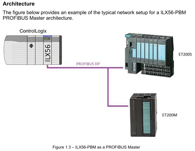
ILX56-PBM is an adaptation of ControlLogix launched by ProSoft Technology ® The PROFIBUS DPV1 master/slave module of the platform enables efficient data exchange between the ControlLogix controller and PROFIBUS DP devices, supports DPV0 cyclic data exchange, DPV1 non cyclic message and alarm functions, and has redundant deployment, flexible configuration, and comprehensive diagnostic capabilities. It is suitable for applications that require the integration of PROFIBUS bus and ControlLogix system in industrial automation, process control, and other scenarios.
Core functions and architecture
1. Work mode and core competencies
ILX56-PBM supports bidirectional switching between master and slave modes, with core functionality covering the full protocol stack of PROFIBUS DPV0/DPV1
Master mode:
Manage up to 125 PROFIBUS DP slave devices, supporting DPV0 cyclic data exchange (up to 5000 bytes of data), DPV1 Class 1 (MS1, only communicates with configured slave devices), and Class 2 (MS2, concurrent communication with multiple master stations) non cyclic messages.
Support DPV1 alarm collection (such as diagnostic alarms and process alarms), which can read device alarm and diagnostic information through the ControlLogix controller, and support automatic device discovery and station address modification.
From mode (Slave):
It can simulate up to 10 PROFIBUS DP slave devices, support DPV0 cyclic data exchange and DPV1 Class 1 messages, and each analog slave device can be configured with independent I/O mapping and alarm triggering mechanisms.
Supports communication with third-party PROFIBUS master stations, automatically adapts data formats to ControlLogix user-defined data types (UDT), and ensures alignment of 16/32-bit data structures.
2. Hardware architecture and interfaces
Physical interface:
PROFIBUS DP port: RS485 standard DB9 female head, supports+5VDC terminal resistor power supply, pins 3 (RxD/TxD-P) and 8 (RxD/TxD-N) are differential data pins, and pin 5 is reference ground.
Expansion interface: onboard SD card slot (supporting FAT32 format for firmware backup and configuration recovery), 2 DIP switches (SW1: forced safe mode for firmware repair); SW2: Configuration lock to prevent accidental modifications.
Indicator lights and display: 3 diagnostic LEDs (RUN/FB/OK)+4-character alphanumeric display screen, real-time display module mode (such as "MASTER" and "SLAVE"), operating status (such as "OPERATE" and "OFFLINE"), and fault information (such as "Bus Fault" and "Duplicate Station").

Configuration and deployment process
1. Configuration tools and preliminary preparations
Core tool: ProSoft PLX50 Configuration Utility (available for download from the official website) needs to be installed for module parameter configuration, GSD file management, device addition, and configuration download; Studio 5000 requires the installation of Add On Profile (AOP, v21 and above versions, v20 and below require the use of the universal 1756 module configuration file).
GSD file management: PROFIBUS devices need to be imported into PLX50 tool through GSD files, supporting GSD directory export/import, and can batch add third-party PROFIBUS devices (such as Siemens ET200M, Schneider ATV frequency converter, etc.).
2. Key configuration steps
(1) Basic parameter configuration
Main mode configuration:
Set the PROFIBUS station address (TS, 0-126, which should not conflict with the slave devices), the highest station address (HSA, it is recommended to set it as the actual maximum slave address to optimize performance), and the baud rate (9.6Kbps-12Mbps, which should match all slave devices).
Configure DPV1 parameters: Enable Class 1/Class 2 messages, enable alarms (such as Pull Plug alarms, process alarms), and set timeout time (such as DPV1 request timeout of 2000ms).
From mode configuration:
Simulate the number of slave devices and station addresses, and each slave device needs to be configured with DPV0 data length, DPV1 object (Slot/Index mapping), and alarm triggering conditions (such as Alarm Trigger tag level switching triggering alarms).
(2) ControlLogix Mapping
Generate Logix L5X files using the PLX50 tool, including UDT (such as master status UDT, slave device data UDT), mapping programs, and controller labels. After importing into Studio 5000, automatically associate module input/output mapping areas.
Mapping rule: Input data (from PROFIBUS devices to ControlLogix) and output data (from ControlLogix to PROFIBUS devices) are packaged into byte arrays and automatically parsed into structured labels (such as MyILX56PBM.ET200M.Input. Data) through generated subroutines.
(3) Redundant deployment (exclusive to main mode)
Redundant architecture: Two ILX56-PBM modules share the same PROFIBUS bus, with identical configurations and support for "one master, one backup" switching. The backup machine automatically takes over the main station role by monitoring bus activity (PROFIBUS Inactive Time parameter, default 22ms).
Key parameters:
Profibus Inactive Time: The inactive time of the bus that determines the failure of the main station by the backup machine should be set as "10ms+2 x maximum packet transmission time".
- ABB
- General Electric
- EMERSON
- Honeywell
- HIMA
- ALSTOM
- Rolls-Royce
- MOTOROLA
- Rockwell
- Siemens
- Woodward
- YOKOGAWA
- FOXBORO
- KOLLMORGEN
- MOOG
- KB
- YAMAHA
- BENDER
- TEKTRONIX
- Westinghouse
- AMAT
- AB
- XYCOM
- Yaskawa
- B&R
- Schneider
- Kongsberg
- NI
- WATLOW
- ProSoft
- SEW
- ADVANCED
- Reliance
- TRICONEX
- METSO
- MAN
- Advantest
- STUDER
- KONGSBERG
- DANAHER MOTION
- Bently
- Galil
- EATON
- MOLEX
- DEIF
- B&W
- ZYGO
- Aerotech
- DANFOSS
- Beijer
- Moxa
- Rexroth
- Johnson
- WAGO
- TOSHIBA
- BMCM
- SMC
- HITACHI
- HIRSCHMANN
- Application field
- XP POWER
- CTI
- TRICON
- STOBER
- Thinklogical
- Horner Automation
- Meggitt
- Fanuc
- Baldor
- SHINKAWA
- Other Brands


