
KEB F5 Elevator Driver Complete Guide
LC30: Maximum torque (%), default 150%. Normal operation needs to be increased to 200-250%. Note: After synchronizing the drive and keyboard, LC30 will be reset to 150%!
LC34: Digital pre torque (used for fixed pre torque value in unloaded weighing devices).
Timer (LT):
LT01: Brake release delay (waiting time for the brake to open after enabling).
LT02: Control the holding off time (low gain time during brake closure).
LT03: Speed start delay (waiting for the brake to fully open before accelerating).
LT10: Brake release delay (delay before the brake closes during shutdown).
LT12: Current holding time (the time to maintain excitation current after the brake is closed).
LT13: Current ramp down time (the time when the current returns to zero).
Selection of Braking Resistors and Monitoring of Braking Transistors
The F5 driver integrates a brake chopper internally, but the resistor needs to be externally connected. The manual provides the minimum and typical braking resistance values for each chassis size. For example:
230V 15hp (G chassis): minimum 8.0 Ω, typical 13 Ω, maximum braking current 50A.
480V 100hp (U chassis): minimum 2.2 Ω, typical 4.3 Ω, maximum braking current 364A.
Key safety function: Brake transistor monitoring (K1/K2 terminals)
To prevent the brake transistor from short circuiting and causing the resistor to continue heating up and catching fire, the F5 driver (especially the version with STO) provides a monitoring relay output (K1/K2). It is a normally closed contact during normal operation. When the brake transistor fails (through), the monitoring circuit detects an abnormality and the K1/K2 contacts disconnect. The user must connect this contact to the external contactor coil to cut off the main power or DC circuit and disconnect the power supply to the resistor in case of a fault. Manual warning: Failure to implement this monitoring circuit may result in overheating of the resistor and cause a fire. The wiring diagram provides three options in section 2.2.16: monitoring through elevator controller, monitoring through DC contactor, and monitoring through line contactor.
Detailed explanation and testing of security functions
The F5-K model is equipped with an STO (Safe Torque Off) interface (X2B), which complies with ISO13849-1 PL e and SIL3. STO input has two independent channels (STO1+/STO1-, STO2+/STO2-), supporting OSSD pulse test signals from safety relays (maximum test interval of 10ms). When any channel or hardware enable (X2A. 16) is removed, the driver immediately blocks the IGBT pulse to achieve safe torque cut-off.
Key timing: Driver modulation possible condition=X2A.16 hardware enabled AND STO1 channel valid AND STO2 channel valid (relationship between the three). The status can be viewed in the DG01 diagnostic parameters (ST-EXT=8192, STO=4096).
Brake release confirmation: The digital input can be configured as "Brake release confirmation" (function 18). The driver will check if the brake switch is open after startup (LT01+LT03+2.5 seconds) and if it is closed after shutdown (LT10+LT12). If no signal is received after the timeout, trigger the 'brake switch fault'. LI20 can set reset behavior (universal reset, automatic reset 3 times, forced manual reset).
Unintended Movement Protection (UIM): enabled through LX21 and LX25. After normal operation, if the position of the motor changes beyond the set distance (default 200mm) in a stationary state, the driver triggers an "accidental movement" fault and needs to be manually reset by pressing F1+F4 at the same time. This feature complies with the latest requirements of EN81-20.
In depth investigation of typical fault codes
The F5 driver displays error messages through the LCD keyboard. The following are the common faults on site and their handling paths.
E.EEP(Error Encoder Interface)
Trigger condition: Absolute encoder serial communication interruption or loss of incremental signal.
Troubleshooting: Check the status of LE12 ("No Communication" indicates cable breakage, "Encoder Count Deviation" indicates A/B signal interference or pulse count mismatch). Try unplugging the encoder plug first. If it doesn't work, perform LE01 reset (press Enter after displaying LE01). After replacing the encoder, the driver will automatically detect the new encoder and clear errors, but must relearn the pole positions (LL05 or LL06).
E.OC(Overcurrent)
Trigger condition: The output current exceeds the peak rated value (see technical data sheet).
Reason: Motor cable grounding or phase to phase short circuit; Motor contactor contact erosion or delayed closure; IGBT short circuit (can be checked through diode testing).
Troubleshooting: Disconnect the motor wire and run the driver in open-loop V/Hz mode (LC01=0). If OC is not reported, the problem lies on the motor side; If OC is still reported, the inverter may be damaged.
E.OP(Overvoltage)
Trigger condition: The DC bus voltage exceeds 840V (480V level) or 400V (240V level).
Reason: The deceleration time is too short; The braking resistor is not connected or has a high resistance value; Brake transistor failure (measuring diode characteristics between PB and++). The input voltage of the braking resistor is 760VDC (480V level).
- ABB
- General Electric
- EMERSON
- Honeywell
- HIMA
- ALSTOM
- Rolls-Royce
- MOTOROLA
- Rockwell
- Siemens
- Woodward
- YOKOGAWA
- FOXBORO
- KOLLMORGEN
- MOOG
- KB
- YAMAHA
- BENDER
- TEKTRONIX
- Westinghouse
- AMAT
- AB
- XYCOM
- Yaskawa
- B&R
- Schneider
- Kongsberg
- NI
- WATLOW
- ProSoft
- SEW
- ADVANCED
- Reliance
- TRICONEX
- METSO
- MAN
- Advantest
- STUDER
- KONGSBERG
- DANAHER MOTION
- Bently
- Galil
- EATON
- MOLEX
- DEIF
- B&W
- ZYGO
- Aerotech
- DANFOSS
- Beijer
- Moxa
- Rexroth
- Johnson
- WAGO
- TOSHIBA
- BMCM
- SMC
- HITACHI
- HIRSCHMANN
- Application field
- XP POWER
- CTI
- TRICON
- STOBER
- Thinklogical
- Horner Automation
- Meggitt
- Fanuc
- Baldor
- SHINKAWA
- Other Brands
- UniOP
- KUKA
- Iba
-
 Omron CJ1G-CPU43H CPU Unit 30K Steps
 -
 OMRON C28P-EDR-D PLC Unit
 -
 SIEMENS S7-300 PLC System
 -
 Schneider TP400-PLC-1411 Board
 -
 Siemens 6FC5203-0AF00-0AA3 Panel
 -
 ALLEN BRADLEY 1754-L28BBB GuardPLC
 -
 Omron E6C3-AG5B-C Encoder
 -
 SCE M68-2000/5 CNC Controller
 -
 SCHNEIDER TM2ALM3LT Module
 -
 OMRON C200H-OV001 Voice Module
 -
 OMRON R88M-H30030 Servo Motor
 -
 Bosch RD500 Indramat Servo Drive RD51.2-4B
 -
 Siemens 6SE7090-0XX84-0AH2 T300 Module
 -
 Omron GRT1-TS2P SmartSlice Thermocouple Input
 -
 Xaar XP55500016 XUSB Drive Electronics
 -
 Siemens 6SL3210-1SE21-8UA0 PM340 Power Module
 -
 Mitsubishi GT2708-VTBA Touch Display 8.4 Inch
 -
 Pasaban Fast I/O MTC-3052 PLC Card
 -
 ABB ACS355-01U-02A4-2 VFD 0.37kW
 -
 Yamatake MAH20-PC2100 Processor Module
 -
 Allen Bradley 1774-P1 PLC Power Supply
 -
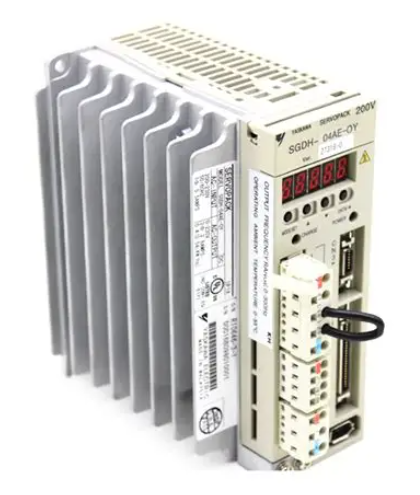 Yaskawa SGDH-04AE-OY 400W Servo Driver
 -
 Omron CPH-X40DT1-D PLC CPU Unit
 -
 Pilz PNOZ mm0.2p Safety PLC Mini 772002
 -
 Siemens 6SL3555-OPR01-0AA0 Sinamics G110M Panel
 -
 Sanyo PLC-XTC50L LCD Projector
 -
 SCE M68-2000 2-Axis Motion Controller
 -
 Omron CS1W-CT021 High-Speed Counter Unit
 -
 Allen Bradley 100E400E 400A Contactor
 -
 Moeller LX-AK/FS-250IEC 250A Fuse Switch
 -
 OMRON FQM1-CM001 Coordinator Module
 -
 Landis+Gyr PCA2.N1 Power Supply
 -
 Mitsubishi Kakoki E-Series I/O Modules
 -
 OMRON R7A-CEA005S Servo Encoder Cable
 -
 Beckhoff EL1918-2200 TwinSAFE Terminal
 -
 OMRON F500-S1 Vision Sensor Camera
 -
 OMRON C200H-RM001-PV1 Master Unit
 -
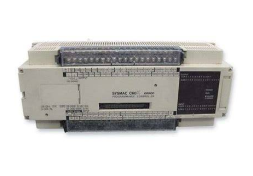
 OMRON C60H-C7DR-DE-V1 PLC CPU
 -
 OMRON NX-PD1000 Power Supply Unit
 -
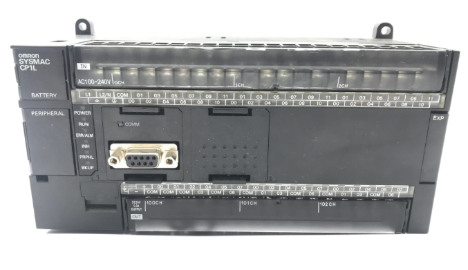
 OMRON CP1L-M60DT-D Micro PLC
 -
 Okuma 1911-2861 Graphic Circuit Board Module
 -
 Yaskawa SGDH-04AE-OY Servo Drive 400W
 -
 Omron R88D-UEP20V Servo Drive
 -
 Oliver 252RP Sakurai Mitsubishi Melsec PM-120M PLC
 -
 Electromatic Denmark SPS 200816 PLC
 -
 Omron FQM1 Flexible Motion Controller System
 -
 Pacer ZE4500 Axiomatic Motion Control Board
 -
 Delta Tau Turbo PMAC2 CPU Board USB Ethernet
 -
 Omron CQM1-CPU42-EV1 PLC CPU
 -
 Omron C500-NC222 Positioning Unit
 -
 ABB SACE TMAX T4 N 250 Circuit Breaker RC222
 -
 Mitsubishi FR A540L 75K E1 Inverter Drive
 -
 Siemens KSP M45 KSP M45 A66 Power Supply Module
 -
 Omron CQM1 TC102 Temperature Control Unit
 -
 Omron C200HW PRT21 Profibus DP Slave Unit
 -
 Yaskawa SGMGH 09DCA6S OY 850W Servo Motor 400V
 -
 Omron R88M UE75030V S1 AC Servo Motor
 -
 Omron C60H C5DR DE V1 PLC CPU Unit
 -
 Okuma 1911 2861 Graphic Card PLC Board Module
 -
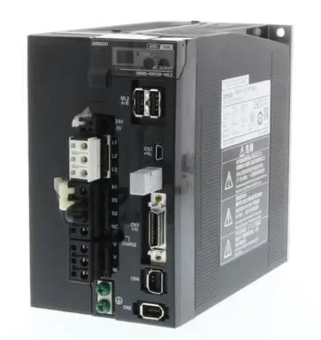
 Omron R88D KN01H ML2 G5 Series Servo Drive
 -
 Laumas TLM8 Ethernet TCP/IP Load Cell Transmitter
 -
 Allen-Bradley 1771-NT2 Thermocouple Input Module
 -
 Siemens 6ES7135-0HF01-0XB0 Analog Output 4AO
 -
 Omron C60H-C6DR-DE-V1 Compact PLC
 -
 HMS Anybus AB7646-F Gateway Profibus to Profinet
 -
 Omron R7M-A10030-BS1 Servo Motor 100W Brake
 -
 Siemens 6SL3555-OPR01-0AA0 G110M Power Supply
 -
 Omron R88M-H10030-B AC Servo Motor 100W
 -
 Omron NJ301-1200 Sysmac NJ3 CPU EtherCAT
 -
 Toshiba H2218592 PLC Control Board Module
 -
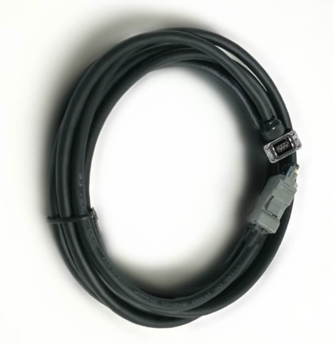 Omron R7A-CEA005S Servo Motor Encoder Cable 5M
 -
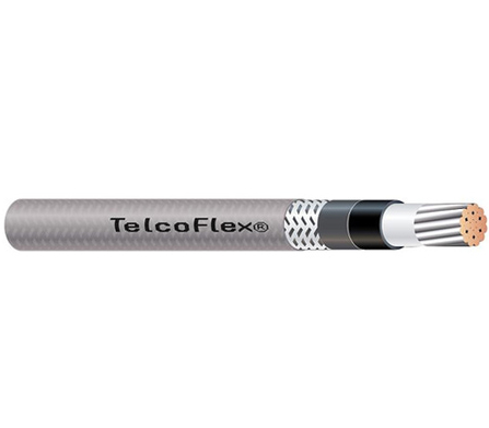 TE.CO TFX 4G 1.5 Grey Cable
 -
 OMRON R88D-HT10 Servo Drive
 -
 OMRON CJ1G-CPU42H PLC CPU
 -
 MASS 106200 Industrial Monitor
 -
 OMRON CJ1W-AD041-V1 Analog Unit
 -
 Phoenix IBS PCI SC/I-T Board
 -
 OMRON ZFX-VS Vision Sensor
 -
 NAIS FP1-C72 PLC Controller
 -
 OMRON R88M-G75030H-BS2 Motor
 -
 SIEMENS A5E02625805-H2 PSU
 -
 Schweitzer SEL-2411 PAC Automation Controller
 -
 Siemens 5WG1-512-1AB11 Switching Actuator KNX
 -
 Stamford MX321-2 Automatic Voltage Regulator AVR
 -
 SCE M68-2000 Dual Axis CNC Servo Drive
 -
 ABB Bailey INNIS21 Network Interface Module
 -
 Omron CJ1W-F159 Loadcell Interface Module
 -
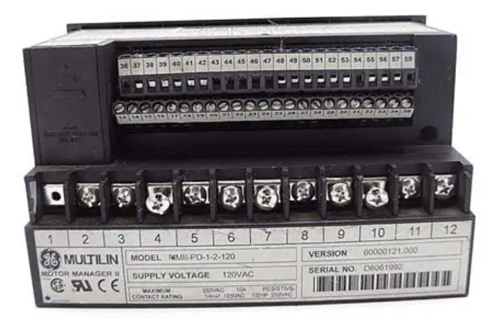 GE Multilin MMII-PD-1-2-120 Motor Manager II
 -
 Yaskawa CIMR-VZ4A0018FAA VFD 5.5 7.5kW
 -
 Siemens 7SJ6001-5EA00-0DA0 Overcurrent Protection Relay
 -
 GE 531X300CCHAFM5 Drive Control PCB Board
 -
 Siemens 7SJ600 Overcurrent Protection Relay SIPROTEC
 -
 Siemens YSUW8 7683 C98043 A7002 Industrial PC Board
 -
 Omron 3G3MX2 A4055 E High Function Inverter Drive
 -
 Omron NB10W TW01B Interactive Display HMI Panel
 -
 Honeywell 30751044-008 Controller II ROM Board
 -
 Omron CJ1W IDP01 Combination Unit IO PLC
 -
 Omron C500 NC222 Position Control Unit PLC
 -
 Omron Z500 MC15E SW17R Vision System Controller
 -
 Sanyo Denki RS1A10AA RTA AC Servo Motor
 -
 Pilz PSS SB 3006 CN-A Compact Safety System PLC
 -
 OMRON C120-SI022 SYSMAC C120 Unit
 -
 SIEMENS 6SE9212-0DA40 MICROMASTER Inverter
 -
 ABB APBU-44C / APBU-44CE Branching Unit Kit
 -
 FANUC A20B-8100-0663 Mainboard
 -
 ABB 1SDA099907R1 Leakage Protection Relay
 -
 ABB IMMFP12 Multi-Function Module
 -
 OMRON CS1W-DA041 Analog Output Unit
 -
 Yaskawa SGMAS-08ACAHC61 Servo Motor
 -
 Benedetti 30.63/T090 3100MOT013_R1 Servo Motor
 -
 Omron C500-ASC02 ASCII Basic Unit Module
 -
 Yaskawa SGMGV-20DDL6F Servo Motor 1.8kW
 -
 ABB OITF-01C 64437496 D Control Board
 -
 TE.CO TFX 4G 1.5 Industrial Grey Cable
 -
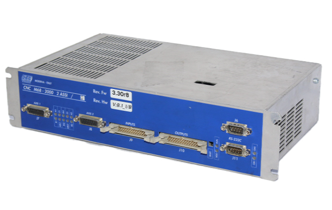 SCE M68-2000 Servo Drive Dual Axis
 -
 Omron C60H-C6DR-DE-V1 CPU Module PLC
 -
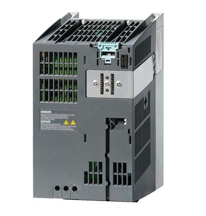 Siemens 6SL3210-1SE21-8UA0 PM340 Power Module
 -
 Siemens 6GK7443-1EX30-0XE0 CP 443-1 Communications Processor
 -
 Siemens 6SL3210-1KE21-7AP1 SINAMICS G120C Drive
 -
 Phoenix UMK-32 RM/MR-G24/1/PLC Active Module
 -
 Omron NS5 SQ00B V2 HMI Touch Screen Industrial Terminal
 -
 Schneider TSX17 20 Micro PLC AEG Programmable Controller
 -
 Omron Z4M T30V2 Z4M H30V Laser Displacement Sensor System
 -
 Yaskawa SGMPH 04AAA61D OY 400W Servo Motor
 -
 Yaskawa CP 9300MC AC Servo Drive Motion Controller
 -
 Merlin Gerin VIP37PT48 Protection Relay Power Management
 -
 Yaskawa SGDH 05AE Sigma II Servo Driver 0.5kW
 -
 Rieter D90 DSP Autoleveller PLC Drawframe Control


