
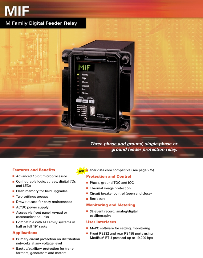
GE Multilin MIF series digital feeder relay
MIF-P type: three-phase+grounding protection relay, suitable for comprehensive protection of three-phase distribution circuits;
MIF-N type: single-phase or ground protection relay, focusing on single-phase circuit or ground fault special protection.
Local operation: Front panel buttons for direct parameter adjustment and status viewing;
Indicator lights (LEDs): LED indicator lights can be configured to visually display the device's operating status and fault type.
Wiring and safety regulations
1. Typical wiring reference
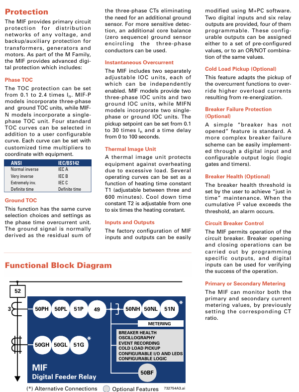
Grounding detection wiring: Two options are available - ① Three phase CT residual current summation (no additional sensors required); ② Zero sequence grounding CT (sensitive detection scenario);
Current input: It is recommended to use a 14 AWG (2.5mm ²) wire, and the terminal should be a fork or ring terminal;
Safe grounding: It is necessary to connect to a safe ground. Terminals B12, A12, and B11 are only for connecting SELV (safety extra low voltage) components (such as PLC), and withstand voltage testing is prohibited.
2. Safety Tips
Overvoltage category: Class II, suitable disconnect devices (switches or circuit breakers) need to be installed near the relay;
Internal fuse: The power circuit is equipped with a 1A/250V fast fuse to protect the equipment in case of malfunction.
Ordering information (model coding rules)
The MIF series model code format is * * MIF * * * * E * 00 * 00 * * *, and the meanings of the characters in each position are as follows, which need to be combined according to actual needs:
Encoding Position Optional Character Meaning Explanation
1st to 3rd digit MIF product identification (digital feeder relay)
The 4th P/N P=three-phase+grounding relay; N=single-phase or grounded relay
5th A/I A=ANSI standard curve; I=IEC standard curve
6th position 0/1/5=MIF-N type; 1=MIF-P type (I n=1A, setting range 0.1-2.4A); 5=MIF-P type (I n=5A, setting range 0.5-12A)
7th position 1/5/N grounding CT rated current: 1=1A (0.1-2.4A); 5=5A(0.5-12A); N=sensitive grounding (1A, 0.005-0.12A)
8th position (empty)/1/2 empty=base model (no options); 1=Option 1 (configurable I/O, event logging, recording); 2=Option 2 (including option 1 function+cold load input, circuit breaker failure/health monitoring, configurable logic)
The power specifications for positions 9-10 are 24-48V DC/AC (19-58V DC); 110-250V DC(88-300V DC); 110-230V AC(88-264V AC)
The installation method for positions 11-12 is empty=independent relay; M+=Installed on M+system (requires additional order of M050 half 19 inch rack or M100 full 19 inch rack, provided free of charge according to the number of relays)
Example
MIF P A 1 1 2 110: Three phase+grounding relay (P), ANSI curve (A), phase CT I n=1A (1), grounding CT I n=1A (1), including option 2 function (2), 110-250V DC power supply (110).
- OMRON
- ABB
- General Electric
- EMERSON
- Honeywell
- HIMA
- ALSTOM
- Rolls-Royce
- MOTOROLA
- Rockwell
- Siemens
- Woodward
- YOKOGAWA
- FOXBORO
- KOLLMORGEN
- MOOG
- KB
- YAMAHA
- BENDER
- TEKTRONIX
- Westinghouse
- AMAT
- AB
- XYCOM
- Yaskawa
- B&R
- Schneider
- KONGSBERG
- NI
- WATLOW
- ProSoft
- SEW
- ADVANCED
- Reliance
- TRICONEX
- METSO
- MAN
- Advantest
- STUDER
- DANAHER MOTION
- Bently
- Galil
- EATON
- MOLEX
- DEIF
- B&W
- ZYGO
- Aerotech
- DANFOSS
- Beijer
- Moxa
- Rexroth
- Johnson
- WAGO
- TOSHIBA
- BMCM
- SMC
- HITACHI
- HIRSCHMANN
- Application field
- XP POWER
- CTI
- TRICON
- STOBER
- Thinklogical
- Horner Automation
- Meggitt
- Fanuc
- Baldor
- SHINKAWA
- Other Brands
- UniOP
- KUKA
- Iba
- Beckhoff
-
 OMRON CJ1W-MD261 Mixed I/O Module
 -
 Omron NJ301-1100 PLC CPU eCat EIP Specs
 -
 Omron F500-C15-ETN Vision System PLC Module
 -
 Modicon M241-24IO TM/T2UK PLC with Ethernet
 -
 SIXNET YS-800-001 RTU PLC Module
 -
 BEMAC UST-202-D Interface Board 1307D V08B2
 -
 Yaskawa JANCD-MMOIC-02 Drive Circuit Board
 -
 ABB 3BSE005028R1 SDCS-COM-1 Comm Board
 -
 Omron 3G3MX2-A4110 A4150 Inverter Drives Specs
 -
 KEYENCE CA-E100 PLC Module
 -
 GE IC693ALG223-GB Analog Input Module Specs
 -
 ABB BAILEY IMMFP01 Multi Function Processor System
 -
 SIEMENS 6FC5372 0AA00 0AA1 NCU 7202 Controller
 -
Modicon TM241CE4 40I O Transistor Programmable Controller
-
 SIEMENS 6ES7 315 2EH13 0AB0 CPU 3152 PN DP
 -
 NORIS A1 91 PCB Card Rack Module System
 -
 SIEMENS 6ES7 313 5BE01 0AB0 Compact CPU
 -
 SCHNEIDER ELECTRIC S144B MICROLOGIC 60A Trip Unit
 -
 CNI PLC269 v3 Control Module Board Rev H
 -
ABB BAILEY IIMCP02 Processor Module
-
 OMRON NT20S ST121 EV3 Operator Interface Terminal
 -
 OMRON NS-CA001 Video Input Unit
 -
 GE Fanuc IC695CHS012 RX3i Backplane
 -
 Allen Bradley 2711E-K14C6 PanelView 1400e Terminal
 -
 Siemens Sinamics CCB 10000432.71 Power Cell
 -
 Siemens 6SL3210-1SE21-8UA0 Power Module PM340
 -
 Yaskawa CIMR-F7A20P4 AC Drive
 -
 Beckhoff EP1918-0002 EtherCAT Box I/O Module
 -
 OMRON CQM1-TC001 Temperature Control Module
 -
 GE Fanuc SGHA36AT0400 Industrial Contactor
 -
 OMRON NJ501-1500 PLC Machine Automation Controller
 -
 Mitsubishi MAZAK QX084 Power Supply MELDAS 500 CNC
 -
 B&R 0AC808.9 PLC Automation Module
 -
 OMRON CP1H-XA40DT1-D PLC Module
 -
 G&W Electric PLC15 5111 011 15kV Capnut Assembly
 -
 GE DS200SLCCG3AGH PCB Circuit Board
 -
 Siemens SINUMERIK 6FC3981-4FD PLC Extension
 -
 OMRON F300-DC I/O Image Processing Unit
 -
 FANUC A06B-0314-B002 AC Servo Motor
 -
 GC-S84 Programmable Controller Logic Module
 -
 PASABAN MONTELEC MTC3001-DC Drive Control PLC
 -
 Allen Bradley 100E460EJ11 Auxiliary Contactor
 -
 Bosch Rexroth 1070075337-101 Card Parameters
 -
 HMS Anybus AB7646-F Gateway Specifications
 -
 Bosch 062633-303401 CNC Servo PLC Card
 -
 TI 500-5023 Series PLC Power Supply
 -
 Siemens C98043-A7002-L1-12 Circuit Board
 -
 Omron E5CC-RX3A5M-000 Controller
 -
 CN-8032-L Profinet Network Adapter Module
 -
 Siemens 3TK2804-0BB4 Safety Relay Details
 -
 Toledo TTLM-2-1M I/O Load Module
 -
 NORIS A1-91 PLC Rack Board Specifications
 -
 Mitsubishi A3ACPUR21 MELSEC PLC CPU Module
 -
 Beckhoff EP7041‑3002 EtherCAT Box Digital Input Module
 -
 REER EOS2E 1053 EOS2R 1053 Safety Light Curtain
 -
 Mitsubishi Q80BD-J71BR11 MELSECNET/H Interface Board
 -
 Omron 3G3IV-B4220-EV2 VFD 400V 22kW
 -
 Allen-Bradley 96844671 1785-LT3 PLC-5/12 Processor Module
 -
 Pasaban MTC3001-DC Drive Control PLC Module
 -
 Omron CJ1M-CPU11 V4.0 PLC CPU Module
 -
 ABB CM579-PNIO B3 Communication Module
 -
 B&R X20 AI 4221 Analog Module
 -
 Siemens 6SY7000-0AC80 PLC Module
 -
 GE 531X300CCHAFM5 Control Card
 -
 AB 810-A15C Inverse Time Relay
 -
 WITTENSTEIN LP120X-MF2-20 Planetary Gear
 -
 Mitsubishi Kakoki E-01B-4130 PLC I/O Modules
 -
 ABB DSQC643 Safety Control Board
 -
 Siemens G26004-A2105-P100-2 PCB
 -
 OMRON F350-C10E Image Processing Unit
 -
 FUJI UG430H-TS1 HMI Touch Panel
 -
 Westronics CB100188-01 Rev F Board
 -
 Siemens 7MH4900-3AA01 Weighing Module
 -
 Gilbert & Nash Tracker 2000 Control Cabinet
 -
 OMRON CJ1M-CPU22 CPU Unit
 -
 OMRON F3SJ-E0625P25 Light Curtain
 -
 Siemens 3VA2340-5HL32-0AA0 Breaker
 -
 Mitsubishi Melsec A61P A2NCPU PLC System
 -
 Aeco 158-02 DSP-02 PCB Card
 -
 FUJI NP1PS-32R CPU Module
 -
 Siemens 6SL3040-1MA01-0AA0 Control Unit CU320-2 PN
 -
 Fuji RYE.75D PLC Driver AC Drive
 -
 Electro Cam PS-6144-24-P16M09-L-MB Programmable Limit Switch
 -
 Siemens C98043-A7001-L2-4 CUD1 Control Board
 -
 Pilz 312070 PSSu H PLC1 FS SN SD Safety Module
 -
 Siemens Plc42q4200atsn Circuit Breaker Fuse Box
 -
 GE Fanuc IC695ALG708-AB Analog Output Module Rx3i
 -
 Siemens 6SE7036-5GK84-1JC2 IGD8 Gate Driver Board
 -
 Charmilles 813078 852029 PLC PCB Robocut 2 CNC EDM
 -
 Siemens 6SL3130-1TE24-0AA0 Smart Line Module
 -
 Pasaban MTC3001-DC Drive Control PLC Module
 -
 Modicon AS-P890-000 Remote I/O Processor Power Supply
 -
 Siemens PXC100-PE96.A PXC Modular Controller
 -
 TOYO KEIKI P:CARD5 AVH-R YH-212 Industrial Control Card
 -
 Omron NS5-SQ00B-V2 HMI Touch Screen 5.7 Inch
 -
 Sciemetric SigPOD 1202-0H00 Data Acquisition Module
 -
 GE Fanuc IC693CPU331W CPU Module Series 90-30
 -
 Square D 8903SVO11V02 Lighting Contactor 200A
 -
 Beckhoff C9900-P224 Power Supply Unit 24V 10A
 -
 HSD PE323 PLC I/O Module
 -
 Pillar AB6406-11A Power Control Board
 -
 GE Fanuc IC693CPU331W CPU Module
 -
 FANUC A61L-0001-0072 LCD Monitor
 -
 AB 20D-D-011-A-0-EYNANANE Drive
 -
 AB 1785-L20B PLC-5/20 Processor
 -
 Siemens SIREC P/PA Recorder 7ND3021
 -
 Siemens D2E160-AH01-17 Fan Blower
 -
 Eaton 101073735-001 LEG Module
 -
 AB 1404-M605B-ENT Powermonitor 3000
 -
 OMRON CJ1W-MAD42 Analog I/O
 -
 Omron CJ1M-CPU13 V3.0 PLC CPU Module
 -
 Pe323 HSD PLC Module Industrial Controller
 -
 Pasaban MTC3001-DC Drive Control PLC Module
 -
 Mitsubishi R02CPU PLC Module MELSEC iQ-R
 -
 B&R X20DC2395 Digital Output Module 32 Ch
 -
 Hoffman A30N24ALP Enclosure with PLC Addons
 -
 Rieter PLC with RMC 24/5V 10 RMC188-1 RMC RIO-1
 -
 Allen-Bradley 1790D-TN4V0 CompactBlock LDX Base Block 4 AI
 -
 National Instruments NI 9242 Analog Input Module 4-Channel
 -
 ABB AO820 3BSE008546R1 Analog Output Module
 -
 Moeller XVC-101-C192K-K82 PLC
 -
 AB 440F-C4000P MatGuard Controller
 -
 AB 1692-ZRCLSS Protection Module
 -
 Schneider S48896 PLC Module
 -
 FANUC A02B-0303-C205 I/O Module
 -
 AB 1785-LT4 PLC-5/10 Processor
 -
 AB 1746-NO8V SLC 500 Analog Output
 -
 OMRON CQM1-TC001 Temperature Unit


