
ABB MNSiS Motor Control Center MConnect Interface
Target users: Control and application engineers who need to obtain MNS iS data and perform system integration, requiring users to have basic knowledge of fieldbus (such as PROFIBUS, Modbus).
ABB MNSiS Motor Control Center MConnect Interface
Core positioning and scope of application
Associated System: Designed specifically for MNS iS System Release 7.6 to guide communication and control integration of MConnect interfaces, supporting the integration of MNS iS as a fieldbus component into PLC or higher-level process control systems (PCS/DCS).
Target users: Control and application engineers who need to obtain MNS iS data and perform system integration, requiring users to have basic knowledge of fieldbus (such as PROFIBUS, Modbus).
Basic concepts and terminology definitions
The document provides explanations for over 30 core terms and abbreviations, covering technical terms, protocols, components, etc. The key terms are as follows:
Abbreviations/full names of terms/Chinese core explanation
Aspect Object ABBAspect is a computerized representation of real/virtual objects (such as pumps, services) that are described and structured through "attributes"
Standardized products that can be directly purchased and used in the COTS commercial spot product market
DTM Device Type Manager is a software module used to manage devices through fieldbus (such as PROFIBUS), supporting frameworks such as PactWare
GSD file device description file (German) PROFIBUS-DP/DP-V1 slave station hardware description file, used for device configuration
MCC motor control center is a switchgear used for motor control and protection, which is one of the core application scenarios of MNS iS
MODBUS RTU Modbus Remote Terminal Unit Protocol Fieldbus Communication Protocol, the core protocol for MConnect and circuit breaker communication
PNIO PROFINET IO is an open standard based on industrial Ethernet (IEC 61158/61784) used for distributed peripheral devices and automation
The SNTP Simple Network Time Protocol is a protocol that controls network time synchronization through Ethernet
The remaining terms (such as HMI, LVS, OPC, etc.) revolve around low-voltage switchgear, communication protocols, and system components, laying the foundation for subsequent technical content.
Hardware and software requirements
1. Hardware requirements
(1) MConnect hardware model and configuration
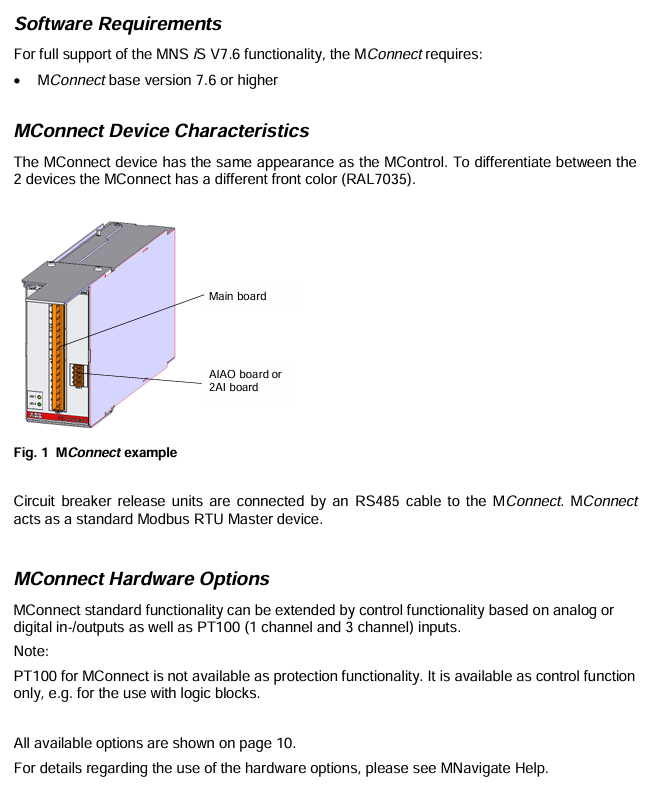
The MConnect hardware is based on the motherboard and is paired with different functional modules (analog input/output, digital input/output, PT100 temperature acquisition) to form 28 models. The core model identification rules are as follows (taking the 1TGE120071R series as an example):
Model ID Core Configuration Function Extension
1TGE120071R1000 motherboard only, no additional IO or temperature acquisition
1TGE120071R1001 motherboard+AIAO (Analog IO) supports analog signal input and output
1TGE120071R1100 motherboard+4DI2DO (24VDC digital IO) with 4 digital inputs and 2 digital outputs (24V DC)
1TGE120071R1500 motherboard+7DI0DO (110VAC-230VAC) 7-channel digital input, no digital output (110-230VAC AC)
1TGE120071R1600 motherboard+PT100-3CH supports 3-channel PT100 temperature acquisition (for control only, non protective function)
(2) Key hardware components
Control Condaptor: A specialized component (model 1TGE102069R0661) used to connect MConnect to MNS iS system, requiring address setting (cabinet number=circuit breaker cabinet number, level=1, position=1).
Communication interface: MConnect is connected to the circuit breaker through RS485 bus, with built-in bus bias and terminal resistance; An external 120 Ω (0.25W) terminal resistor is required on the circuit breaker side to ensure communication stability.
2. Software requirements
Basic version: MConnect requires a basic version of 7.6 or higher to fully support the functionality of MNS iS V7.6.
Auxiliary tools: Parameter settings need to be done in conjunction with MNavigate (Configuration and Management Tool), and some functions can be found in the MNavigate help documentation (such as hardware option usage).
Circuit breaker integration solution
The circuit breaker is the core component of the MNS iS cabinet, and MConnect achieves its monitoring and control through the following methods:
1. Supported circuit breakers and programmable release devices
Remarks on Programmable Release Devices (PR Units) Supported by Circuit Breaker Types
Emax PR122/P, PR123/P classic series, corresponding to PR12x series release
Emax X1, Tmax T7/T7M PR332/P, PR333/P upgrade series, corresponding to PR33x series release
Emax2 Ekip Touch, Ekip Hi Touch, Ekip G Touch, Ekip G Hi Touch intelligent series, supporting richer state and data collection
2. Communication architecture and connections
Communication role: MConnect serves as the Modbus RTU master and communicates point-to-point with the programmable release of the circuit breaker (Modbus slave) through RS485; At the same time, as a gateway, it communicates with MLink through the internal "Switchgear Bus" (10Base-T Ethernet) of MNS iS.
System limitation: Following the MNS iS design rules, each MLink can connect up to 60 devices (including MConnect and MControl), distributed in up to 7 cabinets.
Physical connection: The RS485 bus adopts a three wire system (A/W1, B/W2, shielded wire), and the terminal definitions of different circuit breakers are unified (for example, the A/B terminals of Emax and Emax2 are all W1/W2). Please refer to the document "1SDC007108G0201" for details.
- OMRON
- ABB
- General Electric
- EMERSON
- Honeywell
- HIMA
- ALSTOM
- Rolls-Royce
- MOTOROLA
- Rockwell
- Siemens
- Woodward
- YOKOGAWA
- FOXBORO
- KOLLMORGEN
- MOOG
- KB
- YAMAHA
- BENDER
- TEKTRONIX
- Westinghouse
- AMAT
- AB
- XYCOM
- Yaskawa
- B&R
- Schneider
- KONGSBERG
- NI
- WATLOW
- ProSoft
- SEW
- ADVANCED
- Reliance
- TRICONEX
- METSO
- MAN
- Advantest
- STUDER
- DANAHER MOTION
- Bently
- Galil
- EATON
- MOLEX
- DEIF
- B&W
- ZYGO
- Aerotech
- DANFOSS
- Beijer
- Moxa
- Rexroth
- Johnson
- WAGO
- TOSHIBA
- BMCM
- SMC
- HITACHI
- HIRSCHMANN
- Application field
- XP POWER
- CTI
- TRICON
- STOBER
- Thinklogical
- Horner Automation
- Meggitt
- Fanuc
- Baldor
- SHINKAWA
- Other Brands
- UniOP
- KUKA
- Iba
- Beckhoff
-
 OMRON B7AM-8B16 I/O Terminal Block
 -
 Fanuc A06B-6110-H026 Power Supply Module
 -
 Schneider TSXETG3021 Ethernet Gateway
 -
 OMRON CS1W-CLK21-V1 Controller Link Unit
 -
 NP1W6406T-Z704 PLC I/O Module
 -
 OMRON CJ1W-DA08C Analog Output Module
 -
 Yaskawa 3G3HV-A4022-CE AC Drive
 -
 OMRON NB7W-TW01B CP1L-EL20DR-D Power Panel
 -
 OMRON C500-NC103-E Position Control Unit
 -
 Steag Hamatech PLC DCS Servo Control System
 -
 Siemens 6SN1123-1AA00-0DA1 Power Supply Module
 -
 GE IC693CHS391H CPU & AD693CMM301A PLC Module
 -
 Siemens 6FC5303-0AF23-1AA1 PLC Control Panel
 -
 Square D CM4000T PowerLogic Circuit Monitor J1 F16
 -
 Siemens 6FX5002-5DG10-1BA0 MOTION-CONNECT 500 Cable
 -
 Schmersal SRB324ST 101195504 Safety Relay 24V
 -
 Mitsubishi 15050-PR02A PLC Circuit Board Module
 -
 OMRON CQM1-AD041 Analog Input PLC Module
 -
 Beckhoff EL5042 EtherCAT PLC Terminal Module
 -
 OMRON C200HW-MC402-E Motion Control Unit
 -
 C36TC0UA1100 Industrial Temperature Controller
 -
 NL8048BC24 12 Industrial Control LCD Module
 -
 OMRON R88D Servo Drive and Motor System
 -
 OMRON CS1W CLK21 V1 Controller Link Module
 -
 OMRON YASKAWA R7M A20030 S1 D Servo Motor
 -
 SIEMENS 6AV2128 3KB06 0AX1 Unified Comfort Panel
 -
 Schneider Electric METSEPM8240 PowerLogic Meter
 -
 Advanced AMCI 1PLC 1 31F Programmable Limit Switch
 -
 ABB PM582 ETH Programmable Logic Processor
 -
 SIEMENS 6FC5110 0CB01 0AA0 CPU Control Board
 -
 Schleicher P03GS13A CPU Module
 -
 Siemens 6SN1123-1AA00-0BA1 Power Module
 -
 Mitsubishi A1S61PN Power Supply Module
 -
 Yaskawa CPS-IONB DC Power Supply Module
 -
 Siemens 6ES7215-2BD00 CPU 215-2
 -
 Mitsubishi A2ACPU MELSEC PLC System Kit
 -
 ProSoft 3150-MCM Communication Module
 -
 Mitsubishi OSE104ET Incremental Encoder
 -
 OMRON CJ1W-AD081-V1 Analog Input Module
 -
 Broadcom BCM5464A1KRB Quad Port Ethernet IC
 -
 Modicon M221-24IO TM221C24 PLC 24 PNP Transistor
 -
 Allen-Bradley 1321-3R160-B Line Reactor 3R160B
 -
 Beckhoff CX1020-0012 Embedded PLC Module Specs
 -
 Turck BL20-PF-24VDC-D Power Feed Module Specs
 -
 Siemens 6SY7000-0AC37 Power Supply Module
 -
 Yaskawa SGDH-10DE-OY 1kW 400V Servo Drive Specs
 -
 Omron 3G3SV-BB015-E 1.5kW 220V VFD Specs
 -
 Uni-Pro CPU91-PLC J 23.020167X Processor Module
 -
 PASABAN MTC-3044 PLC Rack Power Supply 4835-A
 -
 XYCOM 3015T Operator Interface Panel BIN4.4.4
 -
 OMRON CJ1W-MD261 Mixed I/O Module
 -
 Omron NJ301-1100 PLC CPU eCat EIP Specs
 -
 Omron F500-C15-ETN Vision System PLC Module
 -
 Modicon M241-24IO TM/T2UK PLC with Ethernet
 -
 SIXNET YS-800-001 RTU PLC Module
 -
 BEMAC UST-202-D Interface Board 1307D V08B2
 -
 Yaskawa JANCD-MMOIC-02 Drive Circuit Board
 -
 ABB 3BSE005028R1 SDCS-COM-1 Comm Board
 -
 Omron 3G3MX2-A4110 A4150 Inverter Drives Specs
 -
 KEYENCE CA-E100 PLC Module
 -
 GE IC693ALG223-GB Analog Input Module Specs
 -
 ABB BAILEY IMMFP01 Multi Function Processor System
 -
 SIEMENS 6FC5372 0AA00 0AA1 NCU 7202 Controller
 -
Modicon TM241CE4 40I O Transistor Programmable Controller
-
 SIEMENS 6ES7 315 2EH13 0AB0 CPU 3152 PN DP
 -
 NORIS A1 91 PCB Card Rack Module System
 -
 SIEMENS 6ES7 313 5BE01 0AB0 Compact CPU
 -
 SCHNEIDER ELECTRIC S144B MICROLOGIC 60A Trip Unit
 -
 CNI PLC269 v3 Control Module Board Rev H
 -
ABB BAILEY IIMCP02 Processor Module
-
 OMRON NT20S ST121 EV3 Operator Interface Terminal
 -
 OMRON NS-CA001 Video Input Unit
 -
 GE Fanuc IC695CHS012 RX3i Backplane
 -
 Allen Bradley 2711E-K14C6 PanelView 1400e Terminal
 -
 Siemens Sinamics CCB 10000432.71 Power Cell
 -
 Siemens 6SL3210-1SE21-8UA0 Power Module PM340
 -
 Yaskawa CIMR-F7A20P4 AC Drive
 -
 Beckhoff EP1918-0002 EtherCAT Box I/O Module
 -
 OMRON CQM1-TC001 Temperature Control Module
 -
 GE Fanuc SGHA36AT0400 Industrial Contactor
 -
 OMRON NJ501-1500 PLC Machine Automation Controller
 -
 Mitsubishi MAZAK QX084 Power Supply MELDAS 500 CNC
 -
 B&R 0AC808.9 PLC Automation Module
 -
 OMRON CP1H-XA40DT1-D PLC Module
 -
 G&W Electric PLC15 5111 011 15kV Capnut Assembly
 -
 GE DS200SLCCG3AGH PCB Circuit Board
 -
 Siemens SINUMERIK 6FC3981-4FD PLC Extension
 -
 OMRON F300-DC I/O Image Processing Unit
 -
 FANUC A06B-0314-B002 AC Servo Motor
 -
 GC-S84 Programmable Controller Logic Module
 -
 PASABAN MONTELEC MTC3001-DC Drive Control PLC
 -
 Allen Bradley 100E460EJ11 Auxiliary Contactor
 -
 Bosch Rexroth 1070075337-101 Card Parameters
 -
 HMS Anybus AB7646-F Gateway Specifications
 -
 Bosch 062633-303401 CNC Servo PLC Card
 -
 TI 500-5023 Series PLC Power Supply
 -
 Siemens C98043-A7002-L1-12 Circuit Board
 -
 Omron E5CC-RX3A5M-000 Controller
 -
 CN-8032-L Profinet Network Adapter Module
 -
 Siemens 3TK2804-0BB4 Safety Relay Details
 -
 Toledo TTLM-2-1M I/O Load Module
 -
 NORIS A1-91 PLC Rack Board Specifications
 -
 Mitsubishi A3ACPUR21 MELSEC PLC CPU Module
 -
 Beckhoff EP7041‑3002 EtherCAT Box Digital Input Module
 -
 REER EOS2E 1053 EOS2R 1053 Safety Light Curtain
 -
 Mitsubishi Q80BD-J71BR11 MELSECNET/H Interface Board
 -
 Omron 3G3IV-B4220-EV2 VFD 400V 22kW
 -
 Allen-Bradley 96844671 1785-LT3 PLC-5/12 Processor Module
 -
 Pasaban MTC3001-DC Drive Control PLC Module
 -
 Omron CJ1M-CPU11 V4.0 PLC CPU Module
 -
 ABB CM579-PNIO B3 Communication Module
 -
 B&R X20 AI 4221 Analog Module
 -
 Siemens 6SY7000-0AC80 PLC Module
 -
 GE 531X300CCHAFM5 Control Card
 -
 AB 810-A15C Inverse Time Relay
 -
 WITTENSTEIN LP120X-MF2-20 Planetary Gear
 -
 Mitsubishi Kakoki E-01B-4130 PLC I/O Modules
 -
 ABB DSQC643 Safety Control Board
 -
 Siemens G26004-A2105-P100-2 PCB
 -
 OMRON F350-C10E Image Processing Unit
 -
 FUJI UG430H-TS1 HMI Touch Panel
 -
 Westronics CB100188-01 Rev F Board
 -
 Siemens 7MH4900-3AA01 Weighing Module
 -
 Gilbert & Nash Tracker 2000 Control Cabinet
 -
 OMRON CJ1M-CPU22 CPU Unit
 -
 OMRON F3SJ-E0625P25 Light Curtain
 -
 Siemens 3VA2340-5HL32-0AA0 Breaker
 -
 Mitsubishi Melsec A61P A2NCPU PLC System


