
Tektronix MSO4000/DPO4000 series digital fluorescence oscilloscope
Tektronix MSO4000/DPO4000 series digital fluorescence oscilloscope
Document Overview
This manual is the official guidance document for the Tektronix MSO4000 (mixed signal) and DPO4000 (digital fluorescence) series oscilloscopes, covering 2-channel (such as MSO4032/DPO4032) and 4-channel (such as MSO4054/DPO4104) models, with a core focus on high-end electronic design and debugging (such as embedded systems, automotive electronics, communication equipment). The document structure includes 11 core chapters and 1 appendix, catering to the complex analysis needs of novice operators and professional engineers, highlighting the ability to synchronously collect and decode "analog+digital" mixed signals, as well as professional measurement functions extended through application modules.
Core parameters and characteristics of the product
1. Model classification and key parameters
Series models, analog channels, digital channels, bandwidth, maximum sampling rate, record length, typical applications
MSO4000 MSO4032 2 2 16 350MHz 2GS/s 10M point mixed signal debugging (such as I2C/SPI)
MSO4000 MSO4054 4 4 16 500MHz 2GS/s 10M point multi-channel timing analysis
MSO4000 MSO4104 4 4 16 1GHz 5GS/s 10M high-speed signal capture (such as USB 2.0)
DPO4000 DPO4034 4-350MHz 2GS/s 10M point analog signal waveform analysis
DPO4000 DPO4104 4-1GHz 5GS/s 10M point high bandwidth signal (such as RF) testing
2. Core Features
Mixed signal analysis (MSO series exclusive): 16 digital channels and analog channels are synchronously collected, supporting MagniVu mode (60.6ps timing resolution), which can capture narrow pulses and edge jitter of digital signals;
High speed signal processing: The highest sampling rate for all channels is 5GS/s, with a recording length of 10M points. It supports a refresh rate of 50000 waveforms per second and can quickly capture transient anomalies;
Flexible triggering and decoding: 8 types of triggering types cover edge, pulse width, logic mode, and bus (such as I2C/CAN/RS-232), supporting sequence triggering (A event+delayed B event);
Professional Expansion Module: Extend functionality through modules such as DPO4PWR (Power Quality/Switching Loss Measurement) and DPO4USB (USB 2.0 Decoding) to meet vertical domain requirements;
Convenient data management: Supports CompactFlash, USB storage, Ethernet remote control (e * Scope), USBTMC protocol for direct connection to PC.
Safety operation standards
1. Electrical safety
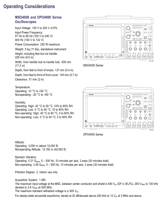
Input voltage limit:
1M Ω input: maximum 400Vpk (DF ≤ 39.2%), 250V RMS (below 130kHz), 20dB/decade attenuation above 130kHz;
50 Ω input: maximum 5V (peak to peak value ≤± 20V), automatically switches to 1M Ω protection when overvoltage occurs;
Probe safety:
P6139A passive probe: CAT II 300V RMS, CAT III 150V RMS, with 20dB/decade attenuation for frequencies above 2.5MHz;
Logic probe P6516: maximum input ± 15V, threshold accuracy ± (100mV+3% threshold);
Grounding requirements: A 3-pin power cord must be used, and the equipment chassis must be reliably grounded. Floating operation is prohibited; During measurement, the reference end of the probe should only be connected to the signal ground and should not be connected to the mains ground.
2. Operation taboos
Do not use in damp (>90% RH) or explosive environments, and avoid liquid contact with equipment;
Before connecting/disconnecting the probe, the signal source must be disconnected first, and live plugging and unplugging are prohibited;
Before disassembling the application module or CF card, it is necessary to shut down and avoid short circuiting the battery or probe contacts.
Basic operation process
1. Probe operation and calibration
Key requirements for operation type steps
Passive probe compensation (P6139A) 1. Probe connected to CH1, set to 10X; 2. Connected to PROBE COMP( 2.5V@1kHz ); 3. Autoset; 4. Adjust the compensation hole to a flat square wave without overshoot/depression, and re compensate every time the channel is changed
Signal Path Compensation (SPC): 1. Disconnect all probes and preheat for 20 minutes; 2. Press 【 Utility 】 → 【 Calibration 】 → 【 Signal Path 】; 3. Wait for 10 minutes and display "Pass". If the environmental temperature difference exceeds 10 ℃ or once a week, ensure low range (≤ 5mV/div) measurement accuracy
Firmware Upgrade 1. Download firmware. img from the official website to the USB root directory; 2. Turn off the oscilloscope and plug it into a USB port, and it will automatically upgrade when turned on; 3. After upgrading, verify the version (Utility ->Config ->About). During the upgrade, it is forbidden to power off or unplug the USB. It is recommended to use a blank USB to avoid file conflicts
2. Channel settings
Simulation channel:
Press the CH1-CH4 button to activate the channel, press 【 Coupling 】 to select DC/AC/GND (AC coupling blocks DC, GND displays reference ground);
Select 1M Ω/50 Ω (50 Ω only DC/GND coupling, maximum 1V/div) according to the 'Impedance' button;
Select Full/250MHz/20MHz (20MHz is used to filter out high-frequency noise) according to [Bandwidth];
Digital Channel (MSO Series):
Press 【 D15-D0 】 to activate the digital channel, and press 【 On/Off 】 to select D7-D0/D15-D8;
- OMRON
- ABB
- General Electric
- EMERSON
- Honeywell
- HIMA
- ALSTOM
- Rolls-Royce
- MOTOROLA
- Rockwell
- Siemens
- Woodward
- YOKOGAWA
- FOXBORO
- KOLLMORGEN
- MOOG
- KB
- YAMAHA
- BENDER
- TEKTRONIX
- Westinghouse
- AMAT
- AB
- XYCOM
- Yaskawa
- B&R
- Schneider
- KONGSBERG
- NI
- WATLOW
- ProSoft
- SEW
- ADVANCED
- Reliance
- TRICONEX
- METSO
- MAN
- Advantest
- STUDER
- DANAHER MOTION
- Bently
- Galil
- EATON
- MOLEX
- DEIF
- B&W
- ZYGO
- Aerotech
- DANFOSS
- Beijer
- Moxa
- Rexroth
- Johnson
- WAGO
- TOSHIBA
- BMCM
- SMC
- HITACHI
- HIRSCHMANN
- Application field
- XP POWER
- CTI
- TRICON
- STOBER
- Thinklogical
- Horner Automation
- Meggitt
- Fanuc
- Baldor
- SHINKAWA
- Other Brands
- UniOP
- KUKA
- Iba
- Beckhoff
- ADLINK
-
 Rolls Royce H1111.0204 Ship Main Controller
 -
 Basler Electric BE3-32-3AC Reverse Power Relay 9 1376 00 105
 -
 Basler Electric BE3-25-1A1N4 Synch Check Relay 9319100100
 -
 Basler Electric SR4A-2B15B3A Static Voltage Regulator
 -
 Basler Electric SR4A-2B15B3E Static Voltage Regulator
 -
 Basler Electric 9170818100 Solid State Protective Relay
 -
 Basler Electric AEC63-7 Analog Excitation Controller
 -
 Basler Electric 17483 Auxiliary Module
 -
 Basler Electric BE1-59 Over Voltage Relay
 -
 Basler Electric 21600-101 Control Module
 -
 Basler Electric KR2F Generator Voltage Regulator 9056600100
 -
 Basler BE1-CDS Current Differential System
 -
 Basler Electric CBS 212 Current Boost System 9 2650 00 100
 -
 Basler Electric IFM-150 Firing Circuit Chassis
 -
 Basler Electric BE1-60 Voltage Balance Relay C1F A1P D0C3F
 -
 Basler Electric BE1-32R Power Relay A2E D1R A0N0F
 -
Basler Electric BE1-32R Power Relay A2E D1R A0N0F
-
 Basler Electric 8650C80G01 Isolation Transducer PCB Board
 -
 ETEL EA-P2M-300-4/7.5A-0100-01 AccurET Modular 300 Servo Drive
 -
 Basler Electric 87T Transformer Differential Relay
 -
 Basler Electric BE-6868 Power Transformer 5950007559202
 -
 Basler Electric PRS250 Veri-Sync Relay 9088800102
 -
 Basler Electric SCP-250-G-60 VAR Power Factor Controller
 -
 Basler DECS-150 AVR 1NS2V1N1S Voltage Regulator
 -
 Basler UFOV 260A Under Frequency Overvoltage Module
 -
 Basler MOC2 199 Motor Operated Control – Overview and Setup
 -
 Basler BE3-49R-5K5A1 Temperature Relay – Complete Guide
 -
Basler BE 20035 001 Transformer – Technical Data and Installation
-
 Basler BE 02727 001 Transformer – Specifications and Usage
 -
 Basler BE127 Under Voltage Relay – Features and Application Guide
 -
Basler CBS377 Current Boost System – Complete Technical Guide
-
 Basler BE1-87G P/N 9170818100 Differential Relay – In-Depth Specs
 -
Basler BE1-87G Generator Differential Relay – Technical Overview
-
Basler Electric SR4A2B16 SVR Static Voltage Regulator – Complete Guide
-
 Basler Electric 9261500101 Power Supply Module
 -
 Basler Electric AEM-2020 Analog Expansion Module
 -
Basler Electric DGC-2020 Digital Genset Controller 51BRBNEAH001
-
Basler Electric BE1-59N Ground Fault Overvoltage Relay
-
 Basler Electric BE1-59N-A5E-E1L-N0S1F Neutral Overvoltage Relay
 -
Basler Electric MOC2499 Motor Operator Control Potentiometer 9072300430
-
 Basler Electric BE1-50/51M Overcurrent Relay
 -
 Basler Electric 9148100106 MOC3502 Solid State Relay 250VDC 0.25A
 -
 Basler Electric CBS 212 Current Boost System 9265000100
 -
 Basler Electric 10493002 Control Module
 -
Basler BE1-32R D3E E1R A0N1F Power Relay
-
 Basler SR8A2B15B3A Static Voltage Regulator
 -
 Basler IFM-105 Firing Circuit Chassis 9324100105
 -
Basler SR4A2B05B3A Static Voltage Regulator
-
 Basler BE151G1EB6PB0N0F Protective Relay
 -
Basler BE1-59 Electric Over Voltage Relay
-
 Basler 277 Static Programmable Powerline Carrier Channel
 -
 Basler BE1-32R D1E A1P A0N1F Power Relay
 -
Basler SR4A1B07B3A Static Voltage Regulator
-
 Basler Electric BE1-700 Digital Protective Relay
 -
Basler Electric SR8A-2B01B3A Static Voltage Regulator
-
 Basler Electric SR4A-2B01B3E Static Voltage Regulator
 -
 Basler Electric 9017709102 PC Board
 -
Basler Electric SR4A-2B01B3A Static Voltage Regulator
-
 Basler Electric PRS-250 Veri-Sync Relay
 -
 Basler Electric 9066800102 Excitation Support System
 -
Basler Electric BE1-87G Generator Differential Relay 9 1708 18 100
-
 Basler Electric 36T865-2 BE03752001 Power Supply
 -
 Basler Electric M-300 149D940G02 Power Supply
 -
 Basler Electric ACA2040-25GM 4Mp 25Fps Area Scan Camera
 -
 Basler BE1-87G-S1A-A1C-A0N0 Differential Relay
 -
Basler SR8A-2B06B3E Static Regulator SR8A2B06B3E
-
 Basler SCP-210 Frequency Controller 9095400100
 -
 Basler BE1-59-A3E-A1J-N1N3F Overvoltage Relay BE159A3EA1JN1N3F
 -
Basler 9 2011 11 100 Bracket Mounted Terminal Unit
-
Basler 9 1606 00 101 Voltage Regulator
-
 Basler CBS-377 Current Boost System 9109600102
 -
 Basler 8650C72 Exciter Control Module PCB Rev 5
 -
 Basler C2EE1PA0N1F BE1-32R Reverse Power Relay
 -
 ADLINK HPCI-14S12U - Industrial Control Backplane 12PCI Backplane PCI-14S Passive Backplane
 -
-0010.png) ADLINK PCIe-GIE74C - image acquisition card 4-CH GigE Vision PoE+ Frame Grabber
ADLINK PCIe-GIE74C - image acquisition card 4-CH GigE Vision PoE+ Frame Grabber -
-0010_1.png) ADLINK PCI-8164 - control card 4-Axis Advanced Motion Controller Board
ADLINK PCI-8164 - control card 4-Axis Advanced Motion Controller Board -
 ADLINK PCIe-U304 - 4 Port USB3 PCIe Frame Grabbers USB Screw Hole Card
 -
 ADLINK PCI-9112 - Multi-Function Data Acquisition Card DAQ Card
 -
 ADLINK PCI-7432 - 51-12013-0A50 4-CH Isolated Numérique I/O PCI Cartes Digital I/O Card
 -
 ADLINK PCA-6106P3-0C1 REV.C1 - backplane 6-Slot Passive Backplane Board
 -
 ADLINK PCI-7224 - 24-CH Opto-Isolated Digital I/O PCI Board
 -
 ADLINK CPCI-7433R(G) - Digital Input Board Rear I/O CompactPCI Card
 -
 ADLINK EBP-13E4 - 51-46703-0A30 Industrial PC Backplane Passive Backplane
 -
 ADLINK PCIE-HDV62 - Image acquisition card High Definition Video Frame Grabber
 -
 ADLINK EBP-13E4 - 51-46703-0A30 Industrial Backplane Board Passive Backplane
 -
 ADLINK 90111-B1 / CPCI-6770 - PCB CPU MODULE CompactPCI Single Board Computer
 -
 ADLINK PCI-7248 - DATA ACQUISITION PCI CARD 48-CH Parallel Digital I/O Board
 -
 ADLINK PCI-7230 - 51-12003-0a50 board PCI7230 32-CH Isolated Digital I/O Card
 -
 ADLINK PCI2A000CB - 51-20000-0B30 Multi-Function DAQ Card Baseboard
 -
 ADLINK PCI-8134-005 - 4-Axis Motion Controller Card
 -
 ADLINK PCI-7224 - 24-CH Opto-Isolated Digital I/O PCI Card
 -
 ADLINK PCI-7434 - 64-CH Isolated Digital Output Card
 -
 ADLINK PCI-8132 - motion control card 2-Axis Servo & Stepper Controller
 -
 ADLINK PCI-8134 - Motion Controller PCI Card 4-Axis Controller Board
 -
 ADLINK PCI-8164 - Motion Control Card 51-12406-0A40 4-Axis Controller
 -
 ADLINK 51-12001-0C20 - Circuit Board Data Acquisition Interface Module Hardware
 -
 ADLINK NuPR0-840 - industrial control motherboard Full-Size PICMG CPU Board
 -
 ADLINK PCI-7444 - 51-12023-0A10 card 128-CH Isolated Digital Output Board
 -
 ADLINK PCI-1612B - data acquisition card 4-Port RS-232/422/485 Serial Communication Card
 -
 ADLINK PCI-6208V 009 - 8/16-CH 16-Bit Analog Output Cards PCB-I-E-482=6BX3
 -
 ADLINK NUPRO-935A/LV - industrial control motherboard Full-Size PICMG SBC Board
 -
 ADLINK PCI-9114DG - Multi-Function DAQ Card Data Acquisition PCI Card
 -
 ADLINK ACL-7130 - Data acquisition card Isolated Digital I/O Board
 -
 ADLINK ABX-6300D-4E1-BP - board ABX6300D4E1BP Video Interface Expansion Card
 -
 ADLINK CPCI-6940 - CPCI-6940/D1539/M16-0(EA)-000E 6U CompactPCI Processor Board
 -
 ADLINK NuPRO-760 - industrial control motherboard Half-Size PICMG SBC CPU Board
 -
 ADLINK IMB-M42H (G)-0020 - industrial control motherboard LGA1155 Micro-ATX Mainboard
 -
 ADLINK RTV-24 / PCI-MP4S - 51-12519-1C30 4-Channel Real Time Video Capture Board
 -
 ADLINK PCI-8134 - 4-Axis Servo & Stepper Motion Controller Card
 -
 ADLINK MXC-6101D - V.PC000.002.ST.00 Box PC Configurable Embedded Computer
 -
.png) ADLINK PCI-8134A - 51-12421-0A10 Motion Control Card 4-Axis Controller Card
ADLINK PCI-8134A - 51-12421-0A10 Motion Control Card 4-Axis Controller Card -
 ADLINK DIN-100S / DIN-100SA1 - Technology SCSI-II TB 100-PIN Terminal Block Board
 -
.png) ADLINK DIN-812M001 / DIN812M001 - 51-14034-0A1 51140340A1 Terminal Module Breakout Interface
ADLINK DIN-812M001 / DIN812M001 - 51-14034-0A1 51140340A1 Terminal Module Breakout Interface -
_1.png) ADLINK PCI-8164 - Servo motion control 4-Axis Advanced Controller Card
ADLINK PCI-8164 - Servo motion control 4-Axis Advanced Controller Card -
 ADLINK PCIe-GIE64 - Acquisition card GigE Vision PoE+ Frame Grabber
 -
 ADLINK M-302 - Industrial control motherboard ATX PC Board Mainboard
 -
 ADLINK PCI-8134 - Motion Controller PCI Card 4-Axis Controller Board
 -
 ADLINK PCI-RTV24 - Image capture card Analog Video Frame Grabber
 -
 ADLINK PCI-8102 - Motion control card 2-Axis Servo & Stepper Controller Board
 -
 ADLINK PCI-9112 REV.B1 - Card Multi-Function Data Acquisition Card
 -
 ADLINK HSI-DI32-M-N / HSL-TB32-M-DIN - Discrete I/O MODULE Distributed Automation Module System
 -
 ADLINK PCI-7296 - IO card REV.A3 96-CH Parallel Digital I/O Card
 -
-0020.png) ADLINK DIN-814P-A4 / 814Y - terminal board Motion Control Interface Block
ADLINK DIN-814P-A4 / 814Y - terminal board Motion Control Interface Block -
 ADLINK DIN-814P-A4 - 51-14056-0A10 PCB-I-E-2736=ZA01 Screw Terminal Board Breakout
 -
 ADLINK M-322 - motherboard Industrial Control Computer Mainboard
 -
 ADLINK NUPRO-406 REV:B1 - industrial control motherboard Full-Size PICMG CPU Board
 -
 ADLINK AMP-204C - card DSP-Based 4-Axis Advanced Pulse-Train Controller
 -
 ADLINK HPCI14S REV.B1 - industrial computer baseboard 14-Slot Passive Backplane


