
Tektronix MSO4000/DPO4000 series digital fluorescence oscilloscope
Set the threshold according to [Thresholds] (such as TTL 1.4V, 3.3V CMOS 1.65V);
Press MagniVu → On to enable 60.6ps timing resolution (for precise measurement of digital edges).

Core functional system
1. Collection system (5 modes)
The working principle of the collection mode is applicable to different scenarios
Sample: equidistant sampling, 1 point/interval regular stable signal (sine wave/square wave), strong real-time performance
Peak Detect records the maximum/minimum value of each interval to capture narrow spikes (≥ 1ns), effective at low-speed time base (≥ 5 μ s/div)
Hi Res (High Resolution) calculates the average value of each interval sample to reduce noise and improve the resolution of low-frequency signals
Envelope records the maximum/minimum waveform collected multiple times, observing the range of signal amplitude changes (such as power ripple fluctuations)
Average: After multiple acquisitions, the average (4/16/64/128 optional) suppresses random noise, and averaging 128 times can significantly improve the signal-to-noise ratio
2. Trigger system (8 types)
Trigger type key parameters applicable scenarios
Edge slope (rising/falling), coupling (DC/LF Reject/HF Reject), stable display of conventional signals (such as clock, square wave)
Pulse Width condition (>/</=/≠), width (33ns-10s), polarity capture of abnormal pulses (such as narrow pulse interference in communication links)
Logic channel status (High/Low/Don't Care), clock edge multi-channel logic combination triggering (such as I2C SDA=1 and SCL=0)
Setup&Hold: Clock channel, data channel, violation time detection bus timing violation (such as insufficient setup time between FPGA and memory)
Bus type (I2C/CAN/RS-32, etc.), trigger conditions (address/data/error), decode and trigger bus specific events (such as Write operation for I2C address 0x7F)
3. Measurement and analysis functions
Automatic measurement: Supports 11 types of parameters, with a maximum of 8 displayed simultaneously. The key measurements are as follows:
Measurement type definition accuracy conditions
The amplitude of the reciprocal signal of the first cycle of frequency (Freq) is ≥ 1div, without any truncation
Rise Time: The time signal with an amplitude of 10% -90% has no noise on the rising edge and is horizontally scale adapted (such as 10ns/div)
Peak to peak value (Pk Pk) full waveform maximum minimum value waveform without truncation, vertical scale adaptation (such as 100mV/div)
FFT spectrum analysis:
Press 【 Math 】 → 【 FFT 】, select the source channel (such as CH1);
Press [Window] to select the window function (Rectangular: optimal frequency resolution; Blackman Harris: excellent amplitude accuracy);
Select dBV RMS/Linear RMS according to 'Vertical Units' (dBV RMS is suitable for multi frequency comparison);
Histogram analysis:
Press 【 Measure 】 → 【 Waveform Histograms 】, select Vertical (voltage)/Horizontal (time);
Set the boundary of the rectangular frame (Horizon. Limits/Vert. Limits) and add statistical measurements (such as σ 1/σ 2/σ 3);
Vertical histograms are used to measure noise (the smaller the σ value, the lower the noise), while horizontal histograms are used to measure jitter.
Data Management and Communication
1. Storage medium operation
Storage content operation steps, file name format, 1MB capacity, approximate storage quantity
Waveform file 1. Press 【 Save/Recall 】 → 【 Save Waveform 】; 2. Select [To File] → [Internal File Format (. ISF)]; 3. Edit file name tekXXXX_Cx.ISF (x=1-4) 18 (10M point waveform)
Set file 1. Press 【 Save/Recall 】 → 【 Save Setup 】; 2. Select [To File] or [To Setup 1-10]; 3. Confirm to save 250 units of tekXXXXX.SET
Screen Image 1. Press 【 Save/Recall 】 → 【 Save Screen Image 】; 2. Select format (. BMP/. TIF/. PNG); 3. Press [OK Save] tekXXXXX.BMP 16
2. Remote communication settings
Ethernet(e*Scope):
Connect the Ethernet cable to the rear panel LAN port, press 【 Utility 】 → 【 I/O 】 → 【 Ethernet Network Settings 】;
Set DHCP to On (automatically obtain IP) or Off (manually set IP);
Input the oscilloscope IP into the PC browser and access the e * Scope interface to control the oscilloscope;
USBTMC (PC Control):
Connect the Rear panel USB Device port of the oscilloscope to the PC using a USB cable;
Install VISA driver (official website download), and send SCPI command through LabVIEW/Excel on the PC end;
Application modules and case studies
1. Optional application modules
Module model, function, applicable scenarios
DPO4PWR power analysis: power quality, switching losses, harmonics, safe working area (SOA) power supply design (such as AC-DC converter efficiency testing)
DPO4USB 2.0 decoding: low-speed/full speed bus triggering and decoding, supporting PID error detection and USB device debugging (such as troubleshooting USB disk enumeration failures)
DPO4AUTO Automotive Bus: CAN/LIN triggering and decoding, supporting frame type/ID filtering for automotive electronics (such as CAN bus communication faults)
DPO4VID video trigger: HDTV (such as 1080i), custom video (3-4000 lines), video equipment (such as monitoring camera signal testing)
2. Typical troubleshooting cases
Case 1: Abnormal RS-232 bus
- OMRON
- ABB
- General Electric
- EMERSON
- Honeywell
- HIMA
- ALSTOM
- Rolls-Royce
- MOTOROLA
- Rockwell
- Siemens
- Woodward
- YOKOGAWA
- FOXBORO
- KOLLMORGEN
- MOOG
- KB
- YAMAHA
- BENDER
- TEKTRONIX
- Westinghouse
- AMAT
- AB
- XYCOM
- Yaskawa
- B&R
- Schneider
- KONGSBERG
- NI
- WATLOW
- ProSoft
- SEW
- ADVANCED
- Reliance
- TRICONEX
- METSO
- MAN
- Advantest
- STUDER
- DANAHER MOTION
- Bently
- Galil
- EATON
- MOLEX
- DEIF
- B&W
- ZYGO
- Aerotech
- DANFOSS
- Beijer
- Moxa
- Rexroth
- Johnson
- WAGO
- TOSHIBA
- BMCM
- SMC
- HITACHI
- HIRSCHMANN
- Application field
- XP POWER
- CTI
- TRICON
- STOBER
- Thinklogical
- Horner Automation
- Meggitt
- Fanuc
- Baldor
- SHINKAWA
- Other Brands
- UniOP
- KUKA
- Iba
-
 LG Display LB315WRM-SVA1 32 Inch 4K LCD Panel
 -
 Mitsubishi Kakoki E Series PLC I/O Modules
 -
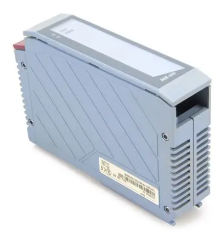
 Allen-Bradley 1440-VST02-01RA Dynamic Measurement Module
 -
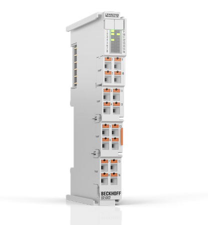 Beckhoff EL5042 EtherCAT Encoder Terminal
 -
 Beckhoff CX5010-0112 Embedded PC Controller
 -
 Guardmaster 440R-D22R2 Safety Relay Specifications
 -
 NL12880BC20-10ND Industrial Display Panel Data
 -
 LFI 12X5326-S1 Slide-in Control Board Technical Data
 -
 Modicon AS-9370-001 Programmable Controller Data
 -
 Mitsubishi Kakoki E-01B-4130 PLC Module Overview
 -
 Guardmaster 440R-D22S2 Dual Input Safety Relay Data
 -
 NL10276AC30-48D Industrial LCD Display Panel Data
 -
 GE ICMFA000000-ABAC Field Control Module Specification
 -
 Siemens 6SN1123-1AB00-0BA1 SIMODRIVE Module Review
 -
 Siemens 6SL3210-1SE23-2AA0 Power Module Technical Data
 -
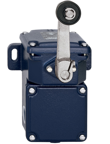 Schmersal T.250-11z-t Limit Switch
 -
 Schmersal T.250-11z-t Limit Switch
 -
 Honeywell 900H32-0102 ControlEdge 900 PLC
 -
 Siemens 6FX1132-1BA01 PCB B84141-A-A40
 -
 BEMAC UST-202-D 1307D PLC Circuit Board
 -
 Mitsubishi HS-MF23-S2A Servo Motor
 -
 B&R 3AI775.6 Analog Input Module
 -
 Omnipure 69003 Rev 11 3-Phase Gate Board PCB
 -
 Pilz 751134 PNOZ s4 C Safety Relay
 -
 Proface PFXGM4301TAD HMI Graphic Panel
 -
 Keyence KV-RC8BXR Programmable Controller
 -
 Siemens 6GK7243-1BX30-0XE0 CP 1243-1 Ethernet Module
 -
 Mitsubishi GT2310-VTBA GT2310-VTBD HMI 10.4 Inch
 -
 Schmersal SRB-NA-R-C.21-24V Safety Relay Module
 -
 Emotron 01-2520-40 M20 Shaft Power Monitor 3x380-500V
 -
 Omron CQM1 SYSMAC PLC System PA203 ID211 OC221
 -
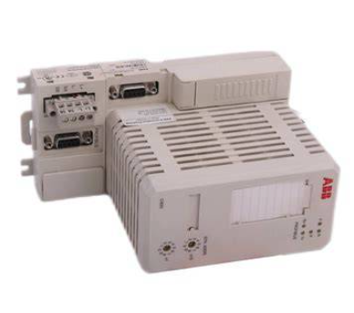 ABB CI830 3BSE013252R1 Profibus DP V1 Module
 -
 B&R 4PP035.0300-01 Power Panel PLC Module
 -
 SICK S30A-6111CL S3000 PROFINET Safety Laser Scanner
 -
 Siemens 6ES7215-1HG40-0XB0 CPU 1215C AC/DC/RLY
 -
 Automation Direct H2-ECOM100 Ethernet Module Details
 -
 Siemens 6GK1143-0TB01 CP 1430 TF Module Review
 -
 Siemens Simatic 505 10 Slot PLC Rack Technical Review
 -
 Automation Direct EZ-SP Message Display Unit
 -
 Mitsubishi A1SJ71QE71N-B5T Ethernet Interface Unit
 -
 Modicon AS-P810-000 Modbus Plus Processor Unit
 -
 Honeywell 51309241-175 TK-PPD011 PWA Specifications
 -
 Omron S8AS-24006N Smart Power Supply Specifications
 -
 Beckhoff EL3218-0018 EtherCAT Terminal Specifications
 -
 Omron CJ1W-PRT21 PROFIBUS-DP Interface Unit
 -
 Inovance AC810-0122-U0R0 PLC Controller
 -
 Cypress CY7C1021CV33-10ZXCT 1Mb SRAM IC
 -
 GE Fanuc IC695CPU315-CD PLC CPU Module RX3i
 -
 Drager 8312088 PCB Safety Module PAC 5500
 -
 Weltronic H70-T02A S430-V1.2 Weld Timer PLC
 -
 B&R 3AM051.6 PLC Analog Input Module
 -
 Schneider BMENOC0301 Communication Module M580
 -
 Mitsubishi FX3UC-32MT-LT PLC Controller
 -
 Omron TZ-1G TZ-1GV TZ-1GV2 TZ-1GV22 Motion Switch
 -
 Mitsubishi AJ71C21-B1-S2 PLC Controller 424749
 -
 Beckhoff EL5042 EtherCAT Encoder Terminal BiSS C
 -
 Eaton easyE4 Programmable Relay 12 Inputs 8 Outputs
 -
 Carel PCO5 P+ 500BAA000L0 Programmable Controller
 -
 Siemens 6ES7223-1PL22-0XA0 EM223 I/O Module 16DI 16DO
 -
 Lenze EMF2179IB DeviceNet Communication Module
 -
 Mitsubishi Q173DCPU Motion CPU Module
 -
 B&R X20AT2222 Temperature Input Module Pt100
 -
 Siemens SITOP UPS1100 Battery Module 7Ah 6EP4134-0GB00-0AY0
 -
 Mitsubishi QJ71DN91 DeviceNet Master Slave Module
 -
B&R X20AO4622 Analog Output Module 4 Channels
-
 B&R X20CP1486 Controller Manual
 -
 Siemens 6ES7134-4GB51-0AB0 Module Manual
 -
 Schneider LMC201CAA10000 Controller Manual
 -
 Fuji Electric NP1L-RS4 Module Guide
 -
 Mitsubishi FX2N-16LNK-M Master Guide
 -
 Yaskawa SGDM-08ADA SGMAH-08AAA41 Manual
 -
 Fanuc A20B-0008-0470 Board Manual
 -
 Calpeda T 70/B Module Specifications
 -
 Eurotherm TC3000 Power Drive Specifications
 -
 Mitsubishi QJ71GP21S-SX Module Manual
 -
 B&R X20AI4622 Analog Input Module 4 Channels
 -
 Siemens Simatic S5 PLC I/O and CPU Modules
 -
 Tel 38950 PCB Board 5044-000171-11 AP9Z-2033A
 -
 Sanyo PLC-XTC50L Multimedia Projector
 -
 Siemens 6GK7243-5DX30-0XE0 CP 243-5 AS-Interface
 -
 Omron V680-CA5D02-V2 RFID Controller
 -
 Pilz 570640 PSEN SL-1.0P Safety Switch
 -
 Schneider LXM62DD27D21000 Servo Drive
 -
 Pilz 401112 PITswitch en1.1a-5m-s Emergency Stop Switch
 -
 Pilz 774350 P2HZ X3 Safety Relay
 -
 Siemens S30810-Q1113-X4-6/02 EWSD Module Board
 -
 Honeywell 30751044-008 ROM PLC Control Board
 -
 Allen-Bradley 440R-W23219 MSR310P Safety Relay
 -
 Siemens 6GK5204-2BB10-2AA3 Industrial Ethernet Switch
 -
 Siemens YSU C32353ADDAGS C98043 PC Board
 -
 Schneider TM241CEC24T PLC Controller Modicon M241
 -
 VARIAN E15000591 PLC PCB Assembly 132102
 -
 Schneider Electric HMIG3U PLC Controller Module
 -
 Siemens 6ES7148-4FC00-0AB0 ET200 IO Module
 -
 Siemens A5E30484420 Simatic IPC Redundant PSU
 -
 Allen Bradley 1771-A3B Chassis Manual
 -
 Schneider BMEH586040 Processor Manual
 -
 Mitsubishi GT2508 Graphic Panel Manual
 -
 Mitsubishi FX2N-16LNK-M Link Module Manual
 -
 Beckhoff EL3011 Analog Terminal Manual
 -
 Siemens 6SN1145-1AA01-0AA1 Infeed Manual
 -
 Proface SP5000 Series Display Specifications
 -
 NUM 0204203001 Axes Board Manual
 -
 Square D LV434001 Ethernet Interface Manual
 -
 Omron NA5 Series HMI Module Specifications
 -
 ABB 57619104E Inverter PCB Control Board
 -
 Allen-Bradley 100-E205ED11 MCS-E Contactor 205A
 -
 Omron NS12-TS01-ECV2 Series Operation Panel
 -
 Allen-Bradley 440R-EM4R2 Guardmaster Safety Relay
 -
 Omron CS1D-DPL01 Duplex System PLC Module
 -
 Beckhoff CX2030-0115 Embedded PC Controller
 -
 ABB Pluto S20 v2 Cfs Safety PLC 2TLA020070R4700
 -
 B&R X20AT4222 Analog Input Module RTD
 -
 Inovance H3U-3624MT PLC Controller
 -
 GE Fanuc IC698CPE010 PLC CPU Module
 -
 Texas Instruments Siemens 505-6208-A Analog Input Module
 -
 VDISP 0035416 Card Module Industrial Display Controller
 -
 HITACHI TX09D80VM3CCA 3.5 Inch LCD Screen 240x320
 -
 Siemens 545 555 1105 1106 PLC Controller
 -
 H2-ECOM100 PLC Communication Module Ethernet
 -
 B&R X20CS1012 PLC Module X20 CS 1012
 -
 Siemens 6ES7212-1HF40-0XB0 PLC Module 24VDC
 -
 Omron C120-0C222 IO Module 3G2A6-0C222
 -
 Electromatic Denmark PLC TYPE 200816 Industrial Controller
 -
 SANYO PLC-XTC50L Projector 50-60Hz LCD Installation
 -
 LTi SO84.450 Servo Drive Controller - 450A Three-Phase BG7
 -
 LTi SO84.375 Servo Drive Controller - 375A Three-Phase BG7
 -
 LTi SO84.325 Servo Drive Controller - 325A Three-Phase BG7


