Welcome to the Industrial Automation website!
Product
Article
NameDescriptionContent

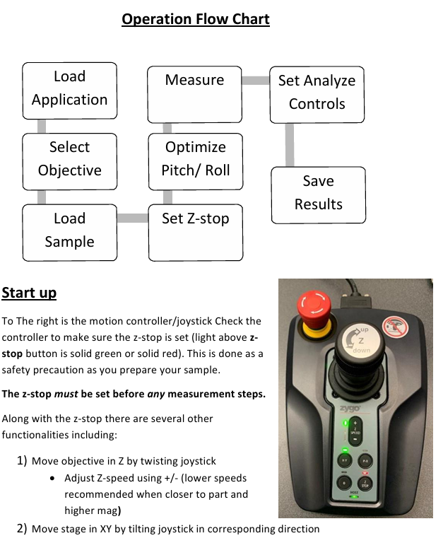
Zygo Device Standard Operating Procedure (SOP)
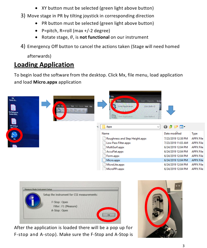
To The right is the motion controller/joystick Check the controller to make sure the z-stop is set (light above z stop button is solid green or solid red).
This is done as a safety precaution as you prepare your sample.
The z-stop must be set before any measurement steps.
This is done as a safety precaution as you prepare your sample.
The z-stop must be set before any measurement steps.
Zygo Device Standard Operating Procedure (SOP)
Start up
To The right is the motion controller/joystick Check the controller to make sure the z-stop is set (light above z stop button is solid green or solid red).
This is done as a safety precaution as you prepare your sample.
The z-stop must be set before any measurement steps.
Along with the z-stop there are several other functionalities including:
1) Move objective in Z by twisting joystick
• Adjust Z-speed using +/- (lower speeds recommended when closer to part and higher mag)
2) Move stage in XY by tilting joystick in corresponding direction
• XY button must be selected (green light above button)
3) Move stage in PR by tilting joystick in corresponding direction
• PR button must be selected (green light above button)
• P=pitch, R=roll (max +/-2 degree)
• Rotate stage, 𝜃, is not functional on our instrument
4) Emergency Off button to cancel the actions taken (Stage will need homed afterwards)
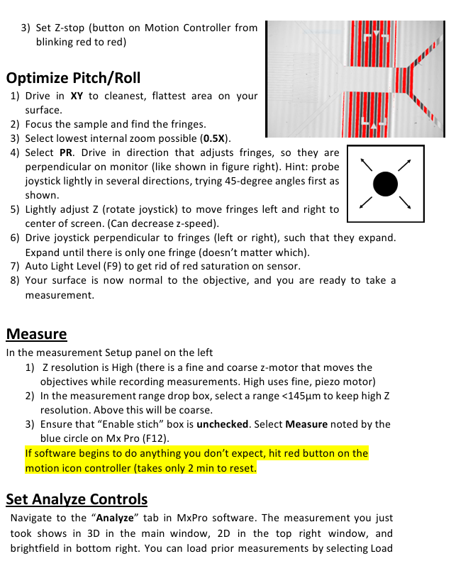
Loading Application
To begin load the software from the desktop. Click Mx, file menu, load application and load Micro.appx application
After the application is loaded there will be a pop up for F-stop and A-stop). Make sure the F-Stop and A-Stop is open (push knobs in) and the filter is set to F1 (measure) as shown on above. Select ok.
Select Objective
Use the software to select the objective you wish to use. The options are 2.5x, 20x, and 50x. There is an internal zoom lens (0.5X, 1X, 2X) to reach finer magnification steps. It’s recommended that you start with the 2.5x objective, 0.5X zoom, and increase in smaller increments. You must always raise the objective high in z before switching objectives to prevent collision.
Load Sample
Ensure objective is sufficiently high. Place sample on stage and align XY rotation by eye since no θ rotation is available. Adjust X and Y on joystick until light from objective is projected onto sample.
Set Z-stop
The Z-Stop has 3 settings noted by the indicator light:
• Blinking red: the z-position is not set (you will also hear an audible beeping sound when trying to move the objective)
• Solid red: the z-position is at the user-set limit
• Solid green: your current position in the z axis is higher than the set z-stop
Procedure:
1) Drive the objective down slowly in Z from a high position (speed can be adjusted on the Motion Controller). Select Auto Light Level (F9).
2) Drive until a surface on sample comes roughly into focus. Slowly drive below that surface and below any features of interest, being careful not to collide with any part of the sample or stage. Look at the bottom computer monitor and part on the stage to do this.
3) Set Z-stop (button on Motion Controller from blinking red to red)
Optimize Pitch/Roll
1) Drive in XY to cleanest, flattest area on your surface.
2) Focus the sample and find the fringes.
3) Select lowest internal zoom possible (0.5X).
4) Select PR. Drive in direction that adjusts fringes, so they are perpendicular on monitor (like shown in figure right). Hint: probe joystick lightly in several directions, trying 45-degree angles first as shown.
5) Lightly adjust Z (rotate joystick) to move fringes left and right to center of screen. (Can decrease z-speed).
6) Drive joystick perpendicular to fringes (left or right), such that they expand. Expand until there is only one fringe (doesn’t matter which).
7) Auto Light Level (F9) to get rid of red saturation on sensor.
8) Your surface is now normal to the objective, and you are ready to take a measurement.
Measure
In the measurement Setup panel on the left
1) Z resolution is High (there is a fine and coarse z-motor that moves the objectives while recording measurements. High uses fine, piezo motor)
2) In the measurement range drop box, select a range <145µm to keep high Z resolution. Above this will be coarse.
3) Ensure that “Enable stich” box is unchecked. Select Measure noted by the blue circle on Mx Pro (F12).
If software begins to do anything you don’t expect, hit red button on the motion icon controller (takes only 2 min to reset.
Set Analyze Controls
Navigate to the “Analyze” tab in MxPro software. The measurement you just took shows in 3D in the main window, 2D in the top right window, and brightfield in bottom right. You can load prior measurements by selecting Load and then loading a .datx file saved earlier. You will likely need to further level your data with post processing.
2D leveling
1) Right-click on main window 3D figure and select 2D.
2) Select “Linear” above window.
3) A slice with arrows will appear. Click in two positions on your image to select the measurement of interest. Note graph below will automatically plot the profile.
4) Right click on graph, add inspector 1. Right click again and add inspector 2.
5) Slide around to your baseline surface. Right click, Level.
3D leveling
1) In the left panel you are in the “Surface” section. Select “Surface Processing” (pop up window appears)
2) Check “Immediate Update” in bottom left. Check “Use Fit Mask.” Select Mask Editor. A window will pop up.
3) Ensure “Form Remove” is checked.
4) Draw geometry to fully characterize the form you are removing.
5) Close out of the mask editor window when finished. The form being removed is shown in lower left.
6) Close out of the surface processing window. Your changes will be automatically implemented to the 3D data set.
Save Results
1) Zygo file(.datx): File>> Save data. Save in Data (D:)ZygoData folder in D drive.
2) Right click on any plot >> Export to export anything as image or 2D plots as . csv files.
Clean Up
1) Raise the objectives to highest point (set z- stop here. Press once to unlock as blinking red. Press again to set as solid red)
2) Close Mx Software, log off Zygo account, Turn off monitor
3) Sign name in Log-book
4) Report any error during use in log-book. Take the Screen shot and save in data folder.
- OMRON
- ABB
- General Electric
- EMERSON
- Honeywell
- HIMA
- ALSTOM
- Rolls-Royce
- MOTOROLA
- Rockwell
- Siemens
- Woodward
- YOKOGAWA
- FOXBORO
- KOLLMORGEN
- MOOG
- KB
- YAMAHA
- BENDER
- TEKTRONIX
- Westinghouse
- AMAT
- AB
- XYCOM
- Yaskawa
- B&R
- Schneider
- KONGSBERG
- NI
- WATLOW
- ProSoft
- SEW
- ADVANCED
- Reliance
- TRICONEX
- METSO
- MAN
- Advantest
- STUDER
- DANAHER MOTION
- Bently
- Galil
- EATON
- MOLEX
- DEIF
- B&W
- ZYGO
- Aerotech
- DANFOSS
- Beijer
- Moxa
- Rexroth
- Johnson
- WAGO
- TOSHIBA
- BMCM
- SMC
- HITACHI
- HIRSCHMANN
- Application field
- XP POWER
- CTI
- TRICON
- STOBER
- Thinklogical
- Horner Automation
- Meggitt
- Fanuc
- Baldor
- SHINKAWA
- Other Brands
- UniOP
- KUKA
- Iba
- Beckhoff
236
-
 Basler D90 96801 100 PCB Card
 -
 Basler XR2002F Voltage Regulator (110 VAC, 48-480 Hz)
 -
 Basler SR8A-2B14B3A Regulator
 -
 Basler 9561500100 Module
 -
 Basler DECS-400 BE1-11 System
 -
 Basler DECS-100-B15 Excitation Control
 -
 Basler SCP 210 Frequency Controller
 -
 Basler SR4A-2B15B3A Static Voltage Regulator
 -
 Basler BE1-32R Power Relay
 -
 Basler PIA2400-17GM Power Interface Adapter
 -
 Basler MVC 232 Manual Voltage Control Module
 -
 Basler SSR 32-12 Static Voltage Regulator
 -
 Basler 5MW AVR Generator Voltage Regulator
 -
 Basler VR63-4B Voltage Regulator
 -
 Basler DECS-100-A05 AVR for Engine Generator
 -
 Basler DECS-100-B15 Automatic Voltage Regulator
 -
 Basler BE1-32R Directional Power Relay
 -
 Basler BE1-87B Differential Relay
 -
 Basler UFOV 260A Protective Module
 -
 Basler 9-2614-02-100 PCB Rev M
 -
Basler DECS-100-B15 Digital AVR
-
 Basler 9284900103 PS DECS-400N
 -
 Basler D4N3H1U Intertie Protection
 -
 Basler DECS-100-B15 A15 AVR
 -
 Basler KR4F Voltage Regulator
 -
 Basler BE26434 T14 Transformer
 -
 Basler SR8A-2B15B3A Regulator
 -
 Westinghouse 774B472A12 AR Relay
 -
Basler DECS-100-B15 AVR
-
Basler XR2002F Regulator 110V
-
Basler SR125-E Static Regulator
-
 Basler SSR 125-12 Regulator
 -
 Basler MOC2599 Motor Pot
 -
 Basler BE1-DFPR Feeder Relay
 -
 Basler CBS 305 Current Boost
 -
 Basler BE1-25 AutoSync
 -
 Basler MVC 300 Voltage Control
 -
 Basler BE3-25A AutoSync
 -
 Basler KR7FF Static Regulator
 -
 Basler 90-49000-100 Regulator
 -
 Basler 880 kVA Dry Type Transformer Specs
 -
 Basler Electric BE1-25 Sync-Check Relay Specs
 -
 Basler SSR 125-12 Voltage Regulator Specs
 -
 Basler Electric BE1-851 Overcurrent Relay Review
 -
Basler Electric 149D930G02 Control Sub-Assembly
-
 Basler Electric BE1-81O/UT Frequency Relay Specs
 -
 Basler Electric BE1-51/27C Overcurrent Relay
 -
 Basler Electric 149D956G02 Industrial Component
 -
Basler Electric BE1-51A Overcurrent Relay Specs
-
 Basler Electric BE1-40Q Loss of Excitation Relay
 -
 Basler DECS-200 Excitation Control System
 -
 Basler DECS-200 Voltage Regulator 56-277V AC / 125V DC
 -
Basler BE1-87T Transformer Differential Relay
-
 Basler RDP-110-S1 Protection Relay
 -
 Basler BE1-700V Digital Protective Relay
 -
 Basler BE1-951 Overcurrent Protection System
 -
 Basler DECS-300 Digital Excitation Control
 -
 Basler DECS-200 Digital Excitation Control
 -
 Basler DECS-200-1C Excitation Control System
 -
Basler DECS-200-1L Digital Excitation Control
-
 Basler Electric BE1-GPS Generator Protection System
 -
Basler Electric DECS-200-1C Digital Excitation Controller
-
 Basler Electric DECS125-15 Excitation Control with Power Module
 -
 Basler Electric BE1-87G Differential Relay
 -
 Basler Electric BE1-11 Protection System I5A3M2P2N0EA00
 -
Basler Electric DECS-200-1C Excitation Control System
-
Basler Electric BE1-11g Generator Protection Relay
-
Basler Electric DECS 125-15-B2C1 V2.0.9 Excitation Control
-
 Basler Electric BE1-81O/UT3ED1JA7N2F Frequency Relay
 -
Basler Electric BE1-81O/UT3EE1YB7N1F Frequency Relay
-
 Basler Electric DECS-200-1L Digital Excitation Control System
 -
Basler DECS125-15-B2C1 Excitation Control
-
 Basler 9507900205 SSR Retrofit Voltage Regulator
 -
 Basler BE2000E Digital Voltage Regulator
 -
 Basler BE1-GPS Generator Protection System
 -
Basler DECS-250-CN1CN1N Digital Excitation Control
-
 Basler DGC-2020 Genset Controller
 -
 Basler BE1-81O UT3ED1LA7N0F Frequency Relay (Variant)
 -
 Basler BE1-81O UT3EE1YA9S0F Frequency Relay (Variant)
 -
Basler BE1-81O Over/Under Frequency Relay
-
Basler DECS125-15 Digital Excitation Control
-
Basler Electric BE1-951 Overcurrent Protection System
-
 Basler Electric BE1-700V Digital Protective Relay
 -
 Basler Electric APR63-5 Automatic Voltage Regulator
 -
Basler Electric BE1-851 Overcurrent Protection System
-
Basler Electric DECS-250-LN1SN1N Excitation Control
-
 Basler Electric BE1-87T Transformer Differential Relay
 -
Basler Electric DECS-200-1L Excitation Control System
-
 Basler Electric 9310300100 DECS-300 Excitation Control
 -
 Basler Electric SSE-N 125-4.5KW Shunt Exciter Regulator
 -
 Basler Electric DGC-2020HD-5NS1DNSBA Genset Controller
 -
Basler Electric BE1-81-O/UT3EE1JB7N1F Frequency Relay
-
Basler Electric BE1-81T1EE1WA0N1F Frequency Relay
-
 Basler Electric BE1-25M1EA6PN5R1F Sync-Check Relay
 -
 Basler Electric BE1-GPS Generator Protection System
 -
Basler Electric DECS-250-LN1SN1N Excitation Control Rev V
-
 Basler Electric DECS-250-CN2CN1N Excitation Control
 -
Basler Electric BE1-50/51B-207 Overcurrent Relay
-
Basler Electric DECS-300-C0N0 Excitation Control System
-
Basler Electric DECS-200 Digital Excitation Control System
-
Basler Electric DECS-250-LN1CN1N Excitation Unit
-
Basler Electric DECS-250 LN2SA1D Excitation Unit Specs
-
Basler Electric BE1-87T Transformer Relay Review
-
Basler Electric BE1-11 Protection System
-
Basler Electric BE1-GPS100-E4N1H1N Protection System
-
 Allen-Bradley 442G-MABH-R Safety Module
 -
 Beckhoff CX1030-0111 PLC Assembly Profile
 -
 FANUC IC693CPU364 PLC Module
 -
 Orange Denmark Type 200816 220 PLC Specs
 -
 OMRON C200H-SNT31 Sysmac PLC Module
 -
 Allen Bradley 20AB022A3AYNANC0 PowerFlex 70
 -
 OMRON C200HW-PCU01 Position Control Unit
 -
 ABB AO845A-eA Analog Output Module
 -
 OMRON CJ1M-CPU22 CPU Unit
 -
 Allen Bradley 100-E265ED11 Contactor
 -
 Honeywell 51304511-100 Interface Module
 -
 SOLEXY BXF3S0101N0018 Gateway Module
 -
 OMRON CJ2H-CPU65 CPU Unit
 -
 Automation Direct GS2-45P0 AC Drive
 -
 M68-2000 2-Axis Motion CNC Controller
 -
 OMRON CJ1M-CPU11 V3.0 PLC CPU Unit
 -
 OMRON CJ1W-NC413 4-Axis Positioning Controller
 -
 OMRON 3G2A3-PRO16 Programming Console HMI
 -
 Siemens 3VT8440-2AA04-2GA2 Molded Case Circuit Breaker
 -
 Siemens 3RT5045 Contactor Series
 -
 OMRON C200HS-CPU01-E SYSMAC PLC Controller
 -
 OMRON C500-NC103-E Positioning Control Unit
 -
 OMRON CJ1W-TC001 Temperature Control Unit
+86-153-9626-8993
WeChat
Contact

Whatsapp

After years of experience, it has developed into a group enterprise entity integrating equipment, industrial, chemical, petroleum equipment, electricity and other products trade and services.
XING-Automation


Product
Copyright © 2026 XING Group All Rights Reserved .