
YASKAWA AC Drive P1000 Industrial Fan and Pump Special Frequency Converter
Protection level: Supports IP20/NEMA 1 (clean environment), IP00/Open Type (requires adapter kit), etc. Some models can upgrade their protection level through the kit.
Core functions: preset fan/pump specific parameters, Auto Tuning, PID control, EZ sleep/wake function, multiple braking modes (DC injection braking, dynamic braking), etc.
YASKAWA AC Drive P1000 Industrial Fan and Pump Special Frequency Converter
Core positioning: Quick Start Guide, to be used in conjunction with the P1000 Series AC Drive Technical Manual (SIEPYAIP1U01). The former focuses on basic installation and trial operation, while the latter provides detailed parameters and advanced feature explanations.
Core specifications of the product
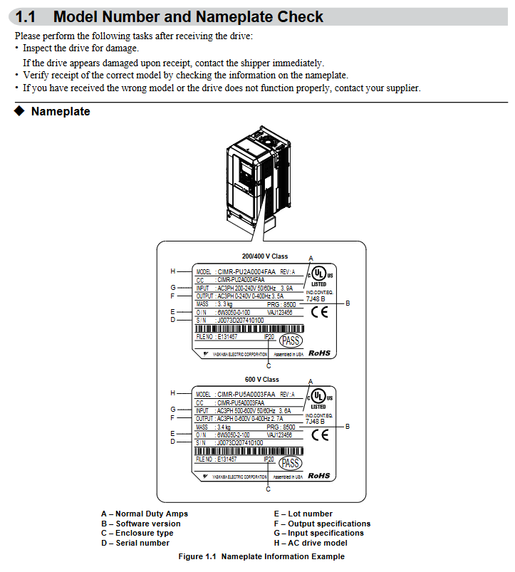
Model coverage:
200 V Class (three-phase): Models 2A0004~2A0415, suitable for motor power of 0.75~175 HP, rated output current of 3.5~415 A;
400 V Class (three-phase): Models 4A0002~4A1200, suitable for motor power of 0.75~1000 HP, rated output current of 2.1~1200 A;
600 V Class (three-phase): models 5A0003~5A0242, suitable for motor power of 1~250 HP, rated output current of 2.7~242 A;
All models are labeled with "ND" (Normal Duty) and are designed specifically for variable torque loads on fans and pumps.
Core features: Support preset application parameters, Auto Tuning, PID closed-loop control, EZ sleep/wake energy-saving function, multiple braking methods (DC injection braking, dynamic braking), in compliance with UL, cUL, CE, RoHS 2 and other certification standards.
Mechanical Installation: Environmental Requirements and Operating Standards
1. Installation environment requirements (must be strictly followed)
Specific requirements for environmental dimensions: Remarks
Temperature IP20/NEMA 1 model: -10~+40 ℃; IP00/Open Type models: -10~+50 ℃. If the temperature exceeds+50 ℃, the capacity needs to be reduced to avoid severe temperature fluctuations
Humidity ≤ 95% RH, no condensation to prevent moisture and short circuit of the circuit board
Altitude ≤ 1000 meters (without capacity reduction); 1000-4000 meters: For every 1000 meters increase, the capacity decreases by 8%. In high-altitude areas, the heat dissipation capacity needs to be evaluated
Avoid direct contact with vibration sources at frequencies of 10-20Hz (9.8m/s ²) and 20-55Hz (5.9m/s ²)
The surrounding environment should be free of dust, oil mist, metal debris, corrosive gases, and direct sunlight. A clean environment is preferred, and suitable protective kits should be selected for harsh environments
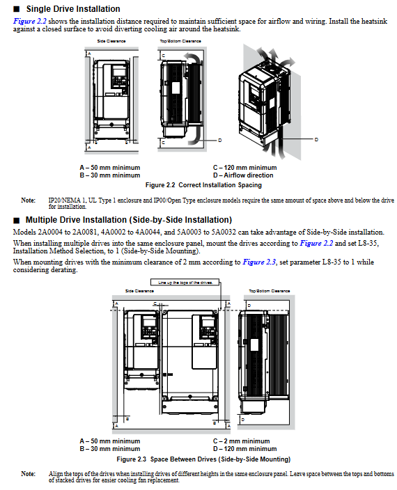
2. Installation method and spacing requirements
Installation direction: Only supports vertical installation. Tilting installation can cause poor heat dissipation and damage to internal components.
Single installation spacing:
Up and down direction: at least 50mm (heat dissipation space);
Left and right direction: at least 30mm (wiring and heat dissipation);
Rear: It should be tightly attached to the enclosed surface to avoid the dispersion of cooling airflow.
Multiple units installed side by side:
Only low-power models (such as 2A0004~2A0081, 4A0002~4A0044) are supported, and the parameter L8-35=1 (Side by Side mode) needs to be set;
The minimum spacing is 2mm, but capacity reduction needs to be considered and aligned with the top of the model to facilitate fan replacement.
3. Precautions for lifting and protection
Use of lifting rings: Some high-power models (such as 2A0360, 4A0250~4A1200) are equipped with lifting rings, and vertical lifting is only used for temporary installation. Long term suspension is prohibited; The lifting of 4A0930/4A1200 requires a suspension angle of ≥ 50 ° to avoid overloading of the lifting ring.
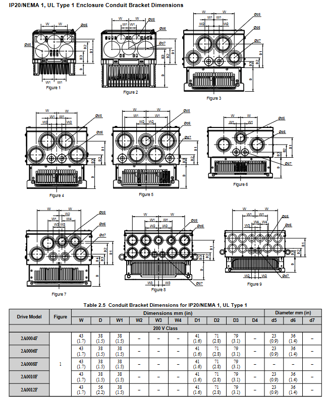
Protection level maintenance: After removing the top protective cover or bottom conduit bracket of IP20/NEMA 1 models, only IP20 protection is retained and NEMA 1 certification is lost.
Electrical installation: wiring specifications and safety requirements
1. Main circuit wiring (prevention and control of core risk points)
Terminal differentiation:
Input terminals (R/L1, S/L2, T/L3): connected to a three-phase power supply, matching the voltage level of the frequency converter (such as 200V level connected to 200-240V, 400V level connected to 380-480V);
Output terminals (U/T1, V/T2, W/T3): connected to the motor, the phase sequence determines the motor direction, and reverse can exchange any two phases ();
Brake terminals (B1, B2): only connect brake resistors/brake units, strictly prohibit connecting other devices.
Wiring requirements:
Wire specifications: Choose according to the rated current of the model. For example, the 2A0004 model uses 14AWG wire for the main circuit, and the 4A1200 model uses 300kcmil wire, and requires the use of ring crimping terminals (UL/cUL certification requirements);
Tightening torque: M4 screws 1.2-1.5N · m, M8 screws 9.9-11N · m. Overtightening may damage the terminals;
Grounding: separate grounding, not sharing grounding wire with high current equipment such as welding machines; The cross-sectional area of the grounding wire for models 4A0414 and above is ≥ 10mm ² (copper) or 16mm ² (aluminum).
2. Control circuit wiring (anti-interference and functional configuration)
Digital input (S1~S8):
Support sinking/sourcing mode, switched through SC-SP/SC-SN jumper, default sinking mode;
Default functions: S1 (forward rotation), S2 (reverse rotation), S3 (external fault), S4 (fault reset), customizable through H1 series parameters.
Analog inputs (A1~A3):
A1/A3 default voltage input (0~10V), A2 default current input (4~20mA), switched through jumper S1;
For frequency setting, it is necessary to set the gain (H3-03/H3-07/H3-11) and bias (H3-04/H3-08/H3-12) to match the signal range (,).
Communication interfaces (R+, R -, S+, S -):
Supports RS-422/RS-485 for MEMOBU/Modbus communication, with the maximum transmission distance being related to the baud rate (up to 115.2kbps);
The terminal resistor (DIP switch S2 set to ON) needs to be enabled at the end of the bus.
3. Handling of special wiring scenarios
Long cable wiring (>50 meters): It is necessary to reduce the carrier frequency (C6-02), set it below 5kHz for 50-100 meters, and below 2kHz for>100 meters to avoid leakage current through large trigger protection (,).
12 pulse rectification (4A0930/4A1200): The jumper wires between R/L1-R1/L11, S/L2-S1/L21, and T/L3-T1/L31 need to be removed, and an external 3-winding transformer (,) needs to be connected.
Start programming and operation: from parameter setting to trial run
1. Use of digital operator (core control interface)
Button functions:
RUN/STOP: Local start/stop, with the STOP key having the highest priority;
LO/RE: Switch between local/remote control, only operable during shutdown;
ESC/ENTER: Return to the previous level/confirm parameters, long press ESC to return to the frequency setting interface ().
Display interpretation:
Status display: "Rdy" (ready), "FWD/REV" (forward/reverse), ALM light (alarm/fault);
Monitoring interface: can view parameters such as output frequency (U1-02), output current (U1-03), PID feedback (U5-01), etc.
2. Core parameter configuration (classified by application scenario)
(1) Basic initialization
Parameter A1-03 (initialization parameter):
0: No initialization;
2220-2 wire system control initialization (S1 forward rotation, S2 reverse rotation);
3330:3 wire system control initialization (S1 start, S2 stop, S5 forward and reverse);
8008~8011: Fan/pump preset (,).
(2) Motor and load adaptation
E2-01 (rated current of motor): It must be strictly set according to the motor nameplate, and will automatically update after automatic tuning;
C1-01/C1-02 (Acceleration/Deceleration Time 1): It is recommended to set the fan/pump load to 60-90 seconds to avoid water/air flow impact;
B1-03 (shutdown mode): default "ramp shutdown" (C1-02), high inertia load can choose "DC injection braking" (b2-02 braking current needs to be set).
(3) Fan/pump specific function
PID control: parameter b5-01=1 enables PID, A2 terminal defaults to feedback signals (such as pressure and flow sensors), b5-19 sets PID setpoint (,);
EZ sleep/wake-up: parameter b5-89=1 enabled, b5-92 sets sleep frequency (such as 0Hz), b5-94 sets wake-up threshold to avoid frequent start stop and save energy (,);
Blockage protection: L3-01=1 (acceleration blockage protection), L3-04=1 (deceleration blockage protection), to avoid overload triggering overcurrent (,).
3. Auto Tuning
Function: Automatically detect motor parameters (stator resistance, leakage inductance, etc.), optimize V/f curve and control accuracy, recommended for first-time use.
Operation steps:
Set T1-01=2 (static tuning, measuring line resistance) or T1-02=3 (dynamic tuning, motor rotation);
Enter the motor nameplate parameters (T1-02 power, T1-04 current, T1-06 pole count, etc.);
Press the RUN key to start tuning, and after completion, display "Tune Successful" (,).
Attention: Dynamic tuning requires disconnecting the motor load to ensure that the motor can rotate freely; Long cables (>50 meters) require static tuning first.
4. Trial operation process (phased verification)
(1) No load trial operation
Step: Disconnect the motor from the load → Set as local control → Start at a given frequency of 6Hz → Check the motor direction, vibration, and current (should be 50% lower than the rated current) → Gradually increase the frequency to the rated value and observe the stability of operation (,).
(2) Test run with load
Preparation: Connect the load and confirm that the emergency stop circuit is effective;
Operation: Starting from low frequency (such as 20Hz), monitor the output current (U1-03), PID feedback (such as whether the pressure is stable), adjust PID parameters (b5-02 proportional gain, b5-03 integration time) to optimize response speed (,).
Troubleshooting and maintenance: ensuring long-term stable operation
1. Common faults and solutions
Possible causes and solutions for fault codes
OC (overcurrent) 1. Motor short circuit/insulation damage; 2. The acceleration and deceleration time is too short; 3. Load blockage 1. Check the motor winding; 2. Extend C1-01/C1-02; 3. Reduce load or increase model size
OV (overvoltage) 1. Input voltage is too high; 2. Slow down too quickly; 3. The braking resistor is not connected. 1. Check the power supply; 2. Extend C1-02 or activate stall protection; 3. Install the braking resistor
OL1 (motor overload) 1. E2-01 is set too low; 2. The load exceeds the rated torque of the motor. 1. Correct E2-01; 2. Verify the load or replace the large motor
FbL (PID feedback low) 1. Sensor disconnection; 2. Feedback signal not connected correctly. 1. Check the sensor and wiring; 2. Confirm the function of terminal A2 (H3-10=B)
2. Regular maintenance plan
(1) Daily inspection (daily)
Appearance: No abnormal noise, odor, or vibration;
Display: No alarm code, stable current/frequency;
Heat dissipation: The fan is running normally and there is no dust blockage.
(2) Regular maintenance (by cycle)
Maintenance project cycle operation requirements
Check the blade wear of the cooling fan after running for 20000 hours and replace it with a fan of the same model
Measure the capacitance of the main circuit capacitor after 5-7 years of operation. If it is lower than 80% of the initial value, it needs to be replaced
Check the torque of the main circuit terminals every 6 months to prevent looseness and heating during terminal tightening
Clean every 3 months by blowing compressed air to remove dust from the radiator (operated after power outage)
3. Maintain monitoring function
Parameters U4-01~U4-04: Display cooling fan, main capacitor IGBT、 The remaining lifespan (percentage) of the control circuit capacitor should be replaced in advance if it is less than 20%.
- OMRON
- ABB
- General Electric
- EMERSON
- Honeywell
- HIMA
- ALSTOM
- Rolls-Royce
- MOTOROLA
- Rockwell
- Siemens
- Woodward
- YOKOGAWA
- FOXBORO
- KOLLMORGEN
- MOOG
- KB
- YAMAHA
- BENDER
- TEKTRONIX
- Westinghouse
- AMAT
- AB
- XYCOM
- Yaskawa
- B&R
- Schneider
- KONGSBERG
- NI
- WATLOW
- ProSoft
- SEW
- ADVANCED
- Reliance
- TRICONEX
- METSO
- MAN
- Advantest
- STUDER
- DANAHER MOTION
- Bently
- Galil
- EATON
- MOLEX
- DEIF
- B&W
- ZYGO
- Aerotech
- DANFOSS
- Beijer
- Moxa
- Rexroth
- Johnson
- WAGO
- TOSHIBA
- BMCM
- SMC
- HITACHI
- HIRSCHMANN
- Application field
- XP POWER
- CTI
- TRICON
- STOBER
- Thinklogical
- Horner Automation
- Meggitt
- Fanuc
- Baldor
- SHINKAWA
- Other Brands
- UniOP
- KUKA
- Iba
- Beckhoff
-
 OMRON C60H C6DR DE V1 Sysmac PLC
 -
 MITSUBISHI ELECTRIC A2ACPU21 S1 CPU Module
 -
 ABB BAILEY INNPM12 Network Process Module
 -
 HONEYWELL 620 0073C IPC PLC Module
 -
 Mitsubishi 15050 PR02B PLC Circuit Board
 -
 SIEMENS 6SY7000 0AC37 Drive Control Module
 -
 OMRON TJ2 ECT16 Traxial EtherCAT Controller
 -
 GE Fanuc IC698PSD300D Power Supply Module
 -
 Texas Instruments Series 505 16 Position Base
 -
 OMRON YASKAWA SGDH 10DE OY Servo Drive
 -
 Allen‑Bradley 440G-MT Safety Interlock Switch Specs
 -
 Rubycon PD27A 24V 8A Power Supply Module
 -
 SK-H1-GDB1-F11D PLC Gate Driver Board Kit
 -
 VIPA 441-4UA14 451-4UA14 PLC Module Rack
 -
 Mitsubishi FX5U-80MT ESS PLC Controller Specs
 -
 Mitsubishi Q64TCRTN Temperature PLC Module
 -
 GE 1C31170G Rev10 PLC Circuit Board Module
 -
 Schneider TWDLMDA40DTK PLC Controller Module
 -
 Omron FQM1-MMA22 Motion Control Module Specs
 -
 OMRON CJ1W-NCF71 Position Control Unit Specs
 -
 Schneider TSXETY4103 Ethernet Module
 -
 Mitsubishi Q12PHCPU Process CPU
 -
 Yaskawa 3G3HV-A4022-CE AC Drive
 -
 Cincinnati Milacron 3-533-0669G Temperature Control Board
 -
 Allen Bradley 20AC030A3AYNANC0 PowerFlex 70 Drive
 -
 Siemens 6ES7314-6BG03-0AB0 CPU 314C-2 DP
 -
 Carrier 17EX54007903 PLC Module
 -
 OMRON CS1W-V600C12 ID Controller Module
 -
 Honeywell 51402755-100 PCB Card
 -
 Heidenhain ECN 113 Rotary Encoder
 -
 OMRON B7AM-8B16 I/O Terminal Block
 -
 Fanuc A06B-6110-H026 Power Supply Module
 -
 Schneider TSXETG3021 Ethernet Gateway
 -
 OMRON CS1W-CLK21-V1 Controller Link Unit
 -
 NP1W6406T-Z704 PLC I/O Module
 -
 OMRON CJ1W-DA08C Analog Output Module
 -
 Yaskawa 3G3HV-A4022-CE AC Drive
 -
 OMRON NB7W-TW01B CP1L-EL20DR-D Power Panel
 -
 OMRON C500-NC103-E Position Control Unit
 -
 Steag Hamatech PLC DCS Servo Control System
 -
 Siemens 6SN1123-1AA00-0DA1 Power Supply Module
 -
 GE IC693CHS391H CPU & AD693CMM301A PLC Module
 -
 Siemens 6FC5303-0AF23-1AA1 PLC Control Panel
 -
 Square D CM4000T PowerLogic Circuit Monitor J1 F16
 -
 Siemens 6FX5002-5DG10-1BA0 MOTION-CONNECT 500 Cable
 -
 Schmersal SRB324ST 101195504 Safety Relay 24V
 -
 Mitsubishi 15050-PR02A PLC Circuit Board Module
 -
 OMRON CQM1-AD041 Analog Input PLC Module
 -
 Beckhoff EL5042 EtherCAT PLC Terminal Module
 -
 OMRON C200HW-MC402-E Motion Control Unit
 -
 C36TC0UA1100 Industrial Temperature Controller
 -
 NL8048BC24 12 Industrial Control LCD Module
 -
 OMRON R88D Servo Drive and Motor System
 -
 OMRON CS1W CLK21 V1 Controller Link Module
 -
 OMRON YASKAWA R7M A20030 S1 D Servo Motor
 -
 SIEMENS 6AV2128 3KB06 0AX1 Unified Comfort Panel
 -
 Schneider Electric METSEPM8240 PowerLogic Meter
 -
 Advanced AMCI 1PLC 1 31F Programmable Limit Switch
 -
 ABB PM582 ETH Programmable Logic Processor
 -
 SIEMENS 6FC5110 0CB01 0AA0 CPU Control Board
 -
 Schleicher P03GS13A CPU Module
 -
 Siemens 6SN1123-1AA00-0BA1 Power Module
 -
 Mitsubishi A1S61PN Power Supply Module
 -
 Yaskawa CPS-IONB DC Power Supply Module
 -
 Siemens 6ES7215-2BD00 CPU 215-2
 -
 Mitsubishi A2ACPU MELSEC PLC System Kit
 -
 ProSoft 3150-MCM Communication Module
 -
 Mitsubishi OSE104ET Incremental Encoder
 -
 OMRON CJ1W-AD081-V1 Analog Input Module
 -
 Broadcom BCM5464A1KRB Quad Port Ethernet IC
 -
 Modicon M221-24IO TM221C24 PLC 24 PNP Transistor
 -
 Allen-Bradley 1321-3R160-B Line Reactor 3R160B
 -
 Beckhoff CX1020-0012 Embedded PLC Module Specs
 -
 Turck BL20-PF-24VDC-D Power Feed Module Specs
 -
 Siemens 6SY7000-0AC37 Power Supply Module
 -
 Yaskawa SGDH-10DE-OY 1kW 400V Servo Drive Specs
 -
 Omron 3G3SV-BB015-E 1.5kW 220V VFD Specs
 -
 Uni-Pro CPU91-PLC J 23.020167X Processor Module
 -
 PASABAN MTC-3044 PLC Rack Power Supply 4835-A
 -
 XYCOM 3015T Operator Interface Panel BIN4.4.4
 -
 OMRON CJ1W-MD261 Mixed I/O Module
 -
 Omron NJ301-1100 PLC CPU eCat EIP Specs
 -
 Omron F500-C15-ETN Vision System PLC Module
 -
 Modicon M241-24IO TM/T2UK PLC with Ethernet
 -
 SIXNET YS-800-001 RTU PLC Module
 -
 BEMAC UST-202-D Interface Board 1307D V08B2
 -
 Yaskawa JANCD-MMOIC-02 Drive Circuit Board
 -
 ABB 3BSE005028R1 SDCS-COM-1 Comm Board
 -
 Omron 3G3MX2-A4110 A4150 Inverter Drives Specs
 -
 KEYENCE CA-E100 PLC Module
 -
 GE IC693ALG223-GB Analog Input Module Specs
 -
 ABB BAILEY IMMFP01 Multi Function Processor System
 -
 SIEMENS 6FC5372 0AA00 0AA1 NCU 7202 Controller
 -
Modicon TM241CE4 40I O Transistor Programmable Controller
-
 SIEMENS 6ES7 315 2EH13 0AB0 CPU 3152 PN DP
 -
 NORIS A1 91 PCB Card Rack Module System
 -
 SIEMENS 6ES7 313 5BE01 0AB0 Compact CPU
 -
 SCHNEIDER ELECTRIC S144B MICROLOGIC 60A Trip Unit
 -
 CNI PLC269 v3 Control Module Board Rev H
 -
ABB BAILEY IIMCP02 Processor Module
-
 OMRON NT20S ST121 EV3 Operator Interface Terminal
 -
 OMRON NS-CA001 Video Input Unit
 -
 GE Fanuc IC695CHS012 RX3i Backplane
 -
 Allen Bradley 2711E-K14C6 PanelView 1400e Terminal
 -
 Siemens Sinamics CCB 10000432.71 Power Cell
 -
 Siemens 6SL3210-1SE21-8UA0 Power Module PM340
 -
 Yaskawa CIMR-F7A20P4 AC Drive
 -
 Beckhoff EP1918-0002 EtherCAT Box I/O Module
 -
 OMRON CQM1-TC001 Temperature Control Module
 -
 GE Fanuc SGHA36AT0400 Industrial Contactor
 -
 OMRON NJ501-1500 PLC Machine Automation Controller
 -
 Mitsubishi MAZAK QX084 Power Supply MELDAS 500 CNC
 -
 B&R 0AC808.9 PLC Automation Module
 -
 OMRON CP1H-XA40DT1-D PLC Module
 -
 G&W Electric PLC15 5111 011 15kV Capnut Assembly
 -
 GE DS200SLCCG3AGH PCB Circuit Board
 -
 Siemens SINUMERIK 6FC3981-4FD PLC Extension
 -
 OMRON F300-DC I/O Image Processing Unit
 -
 FANUC A06B-0314-B002 AC Servo Motor
 -
 GC-S84 Programmable Controller Logic Module
 -
 PASABAN MONTELEC MTC3001-DC Drive Control PLC
 -
 Allen Bradley 100E460EJ11 Auxiliary Contactor
 -
 Bosch Rexroth 1070075337-101 Card Parameters
 -
 HMS Anybus AB7646-F Gateway Specifications
 -
 Bosch 062633-303401 CNC Servo PLC Card
 -
 TI 500-5023 Series PLC Power Supply
 -
 Siemens C98043-A7002-L1-12 Circuit Board
 -
 Omron E5CC-RX3A5M-000 Controller


