
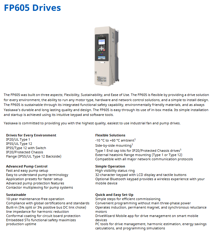
YASKAWA FP605 series industrial fan pump dedicated driver
Flexible adaptation: Supports control of induction motors, permanent magnet motors, and synchronous reluctance motors, adapts to multiple installation environments, is compatible with mainstream industrial communication protocols, and has a simple installation design.
Sustainable operation: Integrated functional safety (STO), using environmentally friendly materials, with a 10-year maintenance free design, built-in 5% voltage divider or 3% positive bus DC link reactor, reducing harmonic interference.
Strong usability: equipped with a high visibility status ring, 32 character LCD touch keyboard, supporting Bluetooth wireless operation and DriveWizard Mobile mobile app management, providing preset parameters for pump applications, and efficient debugging.
YASKAWA FP605 series industrial fan pump dedicated driver
Product core positioning
FP605 is a specialized driver designed for industrial fans and pumps, with core advantages focused on flexibility, sustainability, and ease of use
Flexible adaptation: Supports control of induction motors, permanent magnet motors, and synchronous reluctance motors, adapts to multiple installation environments, is compatible with mainstream industrial communication protocols, and has a simple installation design.
Sustainable operation: Integrated functional safety (STO), using environmentally friendly materials, with a 10-year maintenance free design, built-in 5% voltage divider or 3% positive bus DC link reactor, reducing harmonic interference.
Strong usability: equipped with a high visibility status ring, 32 character LCD touch keyboard, supporting Bluetooth wireless operation and DriveWizard Mobile mobile app management, providing preset parameters for pump applications, and efficient debugging.
Product Model System and Core Specifications
1. Model coding rules (taking "FP65U4005AFA" as an example)
Encoding segment meaning optional values/description
FP65 product series fixed prefix (FP605 series)
U region code U=Americas region
4 voltage levels 2=240V three-phase, 4=480V three-phase
005 rated output current corresponds to rated output current (unit: A, here it is 5A)
A environmental specification A=standard specification
F chassis type F=IP20/UL Type 1, B=IP20/protective chassis, V=IP55/UL Type 12, T=IP55/UL Type 12 with switch, W=flange installation (back of Type 12)
A EMC filter A=No built-in EMC filter (compliant with C2 level standards)
2. Classification of core specifications (by voltage level)
(1) 240V three-phase input (IP20/IP55 multi chassis type)
Rated output chassis frame IP20/UL Type 1 model IP20/protective chassis model IP55/UL Type 12 model IP55/UL Type 12 with switch model flange Type 12 back model
Power (HP) Current (A) FP65U... AFA FP65U... ABA FP65U... AVA FP65U... ATA FP65U... AWA
3 10.6 1 2011AFA - 2011AVA 2011ATA -
5 16.7 1 2017AFA - 2017AVA 2017ATA -
7.5 24.2 2 2024AFA - 2024AVA 2024ATA -
10 30.8 2 2031AFA - 2031AVA 2031ATA -
15 46.2 3 2046AFA - 2046AVA 2046ATA -
20 59.4 3 2059AFA - 2059AVA 2059ATA -
25 74.8 4 2075AFA - 2075AVA 2075ATA -
30 88 4 2088AFA - 2088AVA 2088ATA -
40 114 4 2114AFA - 2114AVA 2114ATA -
50 143 6 2143AFA - 2143AVA 2143ATA -
60 169 6 2169AFA - 2169AVA 2169ATA -
75 211 9 - 2211ABA - - 2211AWA
100 273 9 - 2273ABA - - 2273AWA
125 343 10 - 2343ABA - - 2343AWA
150 396 10 - 2396ABA - - 2396AWA
(2) 480V three-phase input (IP20/IP55 multi chassis type)
Rated output chassis frame IP20/UL Type 1 model IP20/protective chassis model IP55/UL Type 12 model IP55/UL Type 12 with switch model flange Type 12 back model
Power (HP) Current (A) FP65U... AFA FP65U... ABA FP65U... AVA FP65U... ATA FP65U... AWA
3 4.8 1 4005AFA - 4005AVA 4005ATA -
5 7.6 1 4008AFA - - - -
7.5 11 1 4011AFA - 4011AVA 4011ATA -
10 14 1 4014AFA - 4014AVA 4014ATA -
15 21 2 4021AFA - 4021AVA 4021ATA -
20 27 2 4027AFA - 4027AVA 4027ATA -
25 34 2 4034AFA - 4034AVA 4034ATA -
30 40 3 4040AFA - 4040AVA 4040ATA -
40 52 3 4052AFA - 4052AVA 4052ATA -
50 65 3 4065AFA - 4065AVA 4065ATA -
60 77 4 4077AFA - 4077AVA 4077ATA -
75 96 4 4096AFA - 4096AVA 4096ATA -
100 124 4 4124AFA - 4124AVA 4124ATA -
125 156 6 4156AFA - 4156AVA 4156ATA -
150 180 9 - 4180ABA - - 4180AWA
200 240 9 - 4240ABA - - 4240AWA
250 302 9 - 4302ABA - - 4302AWA
300 361 10 - 4361ABA - - 4361AWA
350 414 10 - 4414ABA - - 4414AWA
400 477 11 - 4477ABA - - 4477AWA
450 515 11 - 4515ABA - - 4515AWA
500 590 11 - 4590ABA - - 4590AWA
600 720 11 - 4720ABA - - 4720AWA
3. Protection level and installation adaptation
IP20/UL Type 1: Suitable for clean environments, supports installation inside cabinets (with built-in/external heat sinks) and without cabinets (requires Type 1 adapter).
IP55/UL Type 12: Suitable for limited dust environments, can be directly wall mounted, and some models have switch designs.
Flange Type 12 Back: Suitable for dirty external environments, the heat sink is externally installed inside the Type 12 cabinet without the need for an additional adapter.
Core selection plan (including capacity reduction and installation)
1. Single phase input derating rules
When a three-phase driver is used for single-phase input scenarios, it needs to be reduced in capacity. The core reduction data is as follows (taking 240V/480V as an example):
(1) 240V single-phase input (without reactor)
Driver model (FP65U) Motor power (HP) Motor rated current (A) Output capacity (kVA) Input current (A)
2011 1.0 4.6 1.7 7.4
2017 2.0 7.5 3.2 14
2024 3.0 10.6 4.6 20
2031 3.0 10.6 4.6 20
2046 5.0 17.0 7.3 32
2059 7.5 24 10.3 45
(2) 480V single-phase input (without reactor)
Driver model (FP65U) Motor power (HP) Motor rated current (A) Output capacity (kVA) Input current (A)
4005 1.0 2.1 1.5 3.4
4008 2.0 3.4 2.8 6.1
4011 3.0 4.8 4.1 9.0
4014 3.0 4.8 4.1 9.0
4021 3.0 4.8 4.1 9.0
Solution: Capacity reduction can be avoided through a "single-phase converter (SPC)", such as the 240V 20HP single-phase converter kit (SPBC-240-20HP), which supports a maximum motor load of 20HP, an input current of 79A, and requires a DC link reactor (URX000530).
- OMRON
- ABB
- General Electric
- EMERSON
- Honeywell
- HIMA
- ALSTOM
- Rolls-Royce
- MOTOROLA
- Rockwell
- Siemens
- Woodward
- YOKOGAWA
- FOXBORO
- KOLLMORGEN
- MOOG
- KB
- YAMAHA
- BENDER
- TEKTRONIX
- Westinghouse
- AMAT
- AB
- XYCOM
- Yaskawa
- B&R
- Schneider
- KONGSBERG
- NI
- WATLOW
- ProSoft
- SEW
- ADVANCED
- Reliance
- TRICONEX
- METSO
- MAN
- Advantest
- STUDER
- DANAHER MOTION
- Bently
- Galil
- EATON
- MOLEX
- DEIF
- B&W
- ZYGO
- Aerotech
- DANFOSS
- Beijer
- Moxa
- Rexroth
- Johnson
- WAGO
- TOSHIBA
- BMCM
- SMC
- HITACHI
- HIRSCHMANN
- Application field
- XP POWER
- CTI
- TRICON
- STOBER
- Thinklogical
- Horner Automation
- Meggitt
- Fanuc
- Baldor
- SHINKAWA
- Other Brands
- UniOP
- KUKA
- Iba
- Beckhoff
-
 OMRON C60H C6DR DE V1 Sysmac PLC
 -
 MITSUBISHI ELECTRIC A2ACPU21 S1 CPU Module
 -
 ABB BAILEY INNPM12 Network Process Module
 -
 HONEYWELL 620 0073C IPC PLC Module
 -
 Mitsubishi 15050 PR02B PLC Circuit Board
 -
 SIEMENS 6SY7000 0AC37 Drive Control Module
 -
 OMRON TJ2 ECT16 Traxial EtherCAT Controller
 -
 GE Fanuc IC698PSD300D Power Supply Module
 -
 Texas Instruments Series 505 16 Position Base
 -
 OMRON YASKAWA SGDH 10DE OY Servo Drive
 -
 Allen‑Bradley 440G-MT Safety Interlock Switch Specs
 -
 Rubycon PD27A 24V 8A Power Supply Module
 -
 SK-H1-GDB1-F11D PLC Gate Driver Board Kit
 -
 VIPA 441-4UA14 451-4UA14 PLC Module Rack
 -
 Mitsubishi FX5U-80MT ESS PLC Controller Specs
 -
 Mitsubishi Q64TCRTN Temperature PLC Module
 -
 GE 1C31170G Rev10 PLC Circuit Board Module
 -
 Schneider TWDLMDA40DTK PLC Controller Module
 -
 Omron FQM1-MMA22 Motion Control Module Specs
 -
 OMRON CJ1W-NCF71 Position Control Unit Specs
 -
 Schneider TSXETY4103 Ethernet Module
 -
 Mitsubishi Q12PHCPU Process CPU
 -
 Yaskawa 3G3HV-A4022-CE AC Drive
 -
 Cincinnati Milacron 3-533-0669G Temperature Control Board
 -
 Allen Bradley 20AC030A3AYNANC0 PowerFlex 70 Drive
 -
 Siemens 6ES7314-6BG03-0AB0 CPU 314C-2 DP
 -
 Carrier 17EX54007903 PLC Module
 -
 OMRON CS1W-V600C12 ID Controller Module
 -
 Honeywell 51402755-100 PCB Card
 -
 Heidenhain ECN 113 Rotary Encoder
 -
 OMRON B7AM-8B16 I/O Terminal Block
 -
 Fanuc A06B-6110-H026 Power Supply Module
 -
 Schneider TSXETG3021 Ethernet Gateway
 -
 OMRON CS1W-CLK21-V1 Controller Link Unit
 -
 NP1W6406T-Z704 PLC I/O Module
 -
 OMRON CJ1W-DA08C Analog Output Module
 -
 Yaskawa 3G3HV-A4022-CE AC Drive
 -
 OMRON NB7W-TW01B CP1L-EL20DR-D Power Panel
 -
 OMRON C500-NC103-E Position Control Unit
 -
 Steag Hamatech PLC DCS Servo Control System
 -
 Siemens 6SN1123-1AA00-0DA1 Power Supply Module
 -
 GE IC693CHS391H CPU & AD693CMM301A PLC Module
 -
 Siemens 6FC5303-0AF23-1AA1 PLC Control Panel
 -
 Square D CM4000T PowerLogic Circuit Monitor J1 F16
 -
 Siemens 6FX5002-5DG10-1BA0 MOTION-CONNECT 500 Cable
 -
 Schmersal SRB324ST 101195504 Safety Relay 24V
 -
 Mitsubishi 15050-PR02A PLC Circuit Board Module
 -
 OMRON CQM1-AD041 Analog Input PLC Module
 -
 Beckhoff EL5042 EtherCAT PLC Terminal Module
 -
 OMRON C200HW-MC402-E Motion Control Unit
 -
 C36TC0UA1100 Industrial Temperature Controller
 -
 NL8048BC24 12 Industrial Control LCD Module
 -
 OMRON R88D Servo Drive and Motor System
 -
 OMRON CS1W CLK21 V1 Controller Link Module
 -
 OMRON YASKAWA R7M A20030 S1 D Servo Motor
 -
 SIEMENS 6AV2128 3KB06 0AX1 Unified Comfort Panel
 -
 Schneider Electric METSEPM8240 PowerLogic Meter
 -
 Advanced AMCI 1PLC 1 31F Programmable Limit Switch
 -
 ABB PM582 ETH Programmable Logic Processor
 -
 SIEMENS 6FC5110 0CB01 0AA0 CPU Control Board
 -
 Schleicher P03GS13A CPU Module
 -
 Siemens 6SN1123-1AA00-0BA1 Power Module
 -
 Mitsubishi A1S61PN Power Supply Module
 -
 Yaskawa CPS-IONB DC Power Supply Module
 -
 Siemens 6ES7215-2BD00 CPU 215-2
 -
 Mitsubishi A2ACPU MELSEC PLC System Kit
 -
 ProSoft 3150-MCM Communication Module
 -
 Mitsubishi OSE104ET Incremental Encoder
 -
 OMRON CJ1W-AD081-V1 Analog Input Module
 -
 Broadcom BCM5464A1KRB Quad Port Ethernet IC
 -
 Modicon M221-24IO TM221C24 PLC 24 PNP Transistor
 -
 Allen-Bradley 1321-3R160-B Line Reactor 3R160B
 -
 Beckhoff CX1020-0012 Embedded PLC Module Specs
 -
 Turck BL20-PF-24VDC-D Power Feed Module Specs
 -
 Siemens 6SY7000-0AC37 Power Supply Module
 -
 Yaskawa SGDH-10DE-OY 1kW 400V Servo Drive Specs
 -
 Omron 3G3SV-BB015-E 1.5kW 220V VFD Specs
 -
 Uni-Pro CPU91-PLC J 23.020167X Processor Module
 -
 PASABAN MTC-3044 PLC Rack Power Supply 4835-A
 -
 XYCOM 3015T Operator Interface Panel BIN4.4.4
 -
 OMRON CJ1W-MD261 Mixed I/O Module
 -
 Omron NJ301-1100 PLC CPU eCat EIP Specs
 -
 Omron F500-C15-ETN Vision System PLC Module
 -
 Modicon M241-24IO TM/T2UK PLC with Ethernet
 -
 SIXNET YS-800-001 RTU PLC Module
 -
 BEMAC UST-202-D Interface Board 1307D V08B2
 -
 Yaskawa JANCD-MMOIC-02 Drive Circuit Board
 -
 ABB 3BSE005028R1 SDCS-COM-1 Comm Board
 -
 Omron 3G3MX2-A4110 A4150 Inverter Drives Specs
 -
 KEYENCE CA-E100 PLC Module
 -
 GE IC693ALG223-GB Analog Input Module Specs
 -
 ABB BAILEY IMMFP01 Multi Function Processor System
 -
 SIEMENS 6FC5372 0AA00 0AA1 NCU 7202 Controller
 -
Modicon TM241CE4 40I O Transistor Programmable Controller
-
 SIEMENS 6ES7 315 2EH13 0AB0 CPU 3152 PN DP
 -
 NORIS A1 91 PCB Card Rack Module System
 -
 SIEMENS 6ES7 313 5BE01 0AB0 Compact CPU
 -
 SCHNEIDER ELECTRIC S144B MICROLOGIC 60A Trip Unit
 -
 CNI PLC269 v3 Control Module Board Rev H
 -
ABB BAILEY IIMCP02 Processor Module
-
 OMRON NT20S ST121 EV3 Operator Interface Terminal
 -
 OMRON NS-CA001 Video Input Unit
 -
 GE Fanuc IC695CHS012 RX3i Backplane
 -
 Allen Bradley 2711E-K14C6 PanelView 1400e Terminal
 -
 Siemens Sinamics CCB 10000432.71 Power Cell
 -
 Siemens 6SL3210-1SE21-8UA0 Power Module PM340
 -
 Yaskawa CIMR-F7A20P4 AC Drive
 -
 Beckhoff EP1918-0002 EtherCAT Box I/O Module
 -
 OMRON CQM1-TC001 Temperature Control Module
 -
 GE Fanuc SGHA36AT0400 Industrial Contactor
 -
 OMRON NJ501-1500 PLC Machine Automation Controller
 -
 Mitsubishi MAZAK QX084 Power Supply MELDAS 500 CNC
 -
 B&R 0AC808.9 PLC Automation Module
 -
 OMRON CP1H-XA40DT1-D PLC Module
 -
 G&W Electric PLC15 5111 011 15kV Capnut Assembly
 -
 GE DS200SLCCG3AGH PCB Circuit Board
 -
 Siemens SINUMERIK 6FC3981-4FD PLC Extension
 -
 OMRON F300-DC I/O Image Processing Unit
 -
 FANUC A06B-0314-B002 AC Servo Motor
 -
 GC-S84 Programmable Controller Logic Module
 -
 PASABAN MONTELEC MTC3001-DC Drive Control PLC
 -
 Allen Bradley 100E460EJ11 Auxiliary Contactor
 -
 Bosch Rexroth 1070075337-101 Card Parameters
 -
 HMS Anybus AB7646-F Gateway Specifications
 -
 Bosch 062633-303401 CNC Servo PLC Card
 -
 TI 500-5023 Series PLC Power Supply
 -
 Siemens C98043-A7002-L1-12 Circuit Board
 -
 Omron E5CC-RX3A5M-000 Controller


