
YASKAWA Power Regenerative Unit R1000 Series
400V three-phase series: models 4A03P5~4A0300, suitable for motor power of 5~422HP, rated output current of 7~629A;
All models are designed for "Normal Duty" and optimized for energy regeneration scenarios with variable torque loads.
Core features: Supports 120 ° excitation control, MEMOBU/Modbus communication, PID closed-loop control, automatic fault restart, maintenance life monitoring, and complies with international standards such as UL 508C, IEC/EN 61800-5-1, as well as CE and RoHS compliance requirements.
YASKAWA Power Regenerative Unit R1000 Series
Core specifications of the product
Model coverage:
200V three-phase series: models 2A03P5~2A0105, suitable for motor power of 5~141HP, rated output current of 14~413A;
400V three-phase series: models 4A03P5~4A0300, suitable for motor power of 5~422HP, rated output current of 7~629A;
All models are designed for "Normal Duty" and optimized for energy regeneration scenarios with variable torque loads.
Core features: Supports 120 ° excitation control, MEMOBU/Modbus communication, PID closed-loop control, automatic fault restart, maintenance life monitoring, and complies with international standards such as UL 508C, IEC/EN 61800-5-1, as well as CE and RoHS compliance requirements.
Receiving and unboxing inspection
1. Safety precautions
It is prohibited to transport equipment through the front cover or terminal cover to avoid damage caused by the main body falling;
When handling equipment and circuit boards, it is necessary to follow the electrostatic discharge (ESD) process to prevent circuit damage.
2. Model and nameplate verification
Key information on the nameplate: model (such as CIMR-RU2A0073AAA), rated capacity, input/output specifications, software version, serial number, and place of origin (Japan);
Model interpretation: Taking "CIMR-RU2A0073AAA" as an example, "RU" represents the R1000 series, "2A" is the 200V level, "0073" is the rated output capacity code, and "AAA" is the standard configuration.
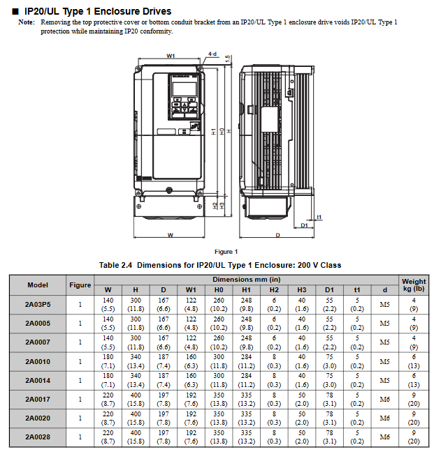
3. Classification of enclosure types
IP20/UL Type 1: Suitable for indoor wall mounted or control cabinet installation, retaining IP20 protection even after removing the top protective cover;
IP00/Open Type: It needs to be installed inside a protective panel, without additional shell protection, and relies on external environmental isolation.
Mechanical Installation: Environmental Requirements and Operating Standards
1. Installation environment requirements
Specific requirements for environmental dimensions: Remarks
Temperature IP00 model: -10~+50 ℃; IP20 model: -10~+40 ℃ overheating requires capacity reduction to avoid severe temperature fluctuations
Humidity ≤ 95% RH, no condensation to prevent moisture and short circuit of the circuit board
Altitude ≤ 1000 meters (without capacity reduction); 1000~3000 meters: For every 100 meters increase, the capacity is reduced by 1%. At high altitudes, the heat dissipation capacity needs to be evaluated
Vibration low-power models (2A03P5~2A0053, etc.): 10-20Hz (9.8m/s ²), 20-55Hz (5.9m/s ²); High power models (2A0073~2A0105, etc.): 20~55Hz (2.0m/s ²) Avoid direct contact with vibration sources
The surrounding environment should be free of dust, oil mist, metal debris, corrosive gases, and direct sunlight. Installation on flammable surfaces or placement of flammable materials is prohibited
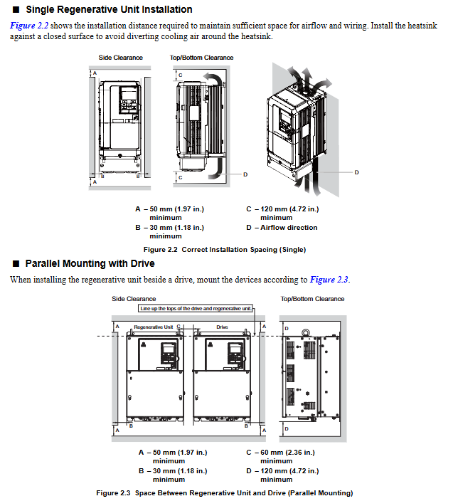
2. Installation method and spacing requirements
Installation direction: Only supports vertical installation. Tilting can cause poor heat dissipation and damage to internal components.
Single installation spacing:
Up and down direction: at least 120mm (heat dissipation space);
Left and right direction: at least 30mm (wiring and heat dissipation);
Rear: It should be tightly attached to the enclosed surface to avoid the dispersion of cooling airflow.
Side by side installation (with drive):
Ordinary side by side: minimum spacing of 50mm, top aligned;
Tightly side by side (only for low-power models 2A03P5~2A0028, etc.): spacing of 2mm, parameter L8-35=1 needs to be set, while considering capacity reduction.
3. Precautions for lifting and protection
High power models (2A0073, 2A0105, etc.) are equipped with lifting rings and are only used for temporary installation. Long term suspension is prohibited;
When lifting vertically, it is necessary to first fix the front cover, terminal block and other components. The vibration/impact during suspension should not exceed 1.96m/s ², and flipping or leaving unattended is prohibited.
Electrical installation: wiring specifications and safety requirements
1. Main circuit wiring (prevention and control of core risk points)
Terminal differentiation:
Input terminals (R/L1, S/L2, T/L3): connected to three-phase power supply, matched with equipment voltage level (200V level connected to 200~240V, 400V level connected to 380~480V);
Output terminals (+, -): Connect to the DC bus of the driver, be careful not to reverse the positive and negative poles;
Voltage detection terminals (r1/11, l/21, t1/31): detect the phase sequence and voltage of the input power supply, and take power from the primary side of the power coordination reactor.
Wiring requirements:
Wire specifications: Select according to the rated current of the model. For example, 2A03P5 uses 14AWG (American standard) or 3.5mm ² (European standard) wire, 4A0300 uses 300kcmil wire, and circular crimping terminals are required;
Tightening torque: M4 screws 2.1~2.3N · m, M8 screws 5.4~6.0N · m, excessive tightening may damage the terminals;
Grounding: Independently grounded, not sharing grounding wire with high current equipment such as welding machines; Grounding resistance of 200V level ≤ 100 Ω, 400V level ≤ 10 Ω.
- OMRON
- ABB
- General Electric
- EMERSON
- Honeywell
- HIMA
- ALSTOM
- Rolls-Royce
- MOTOROLA
- Rockwell
- Siemens
- Woodward
- YOKOGAWA
- FOXBORO
- KOLLMORGEN
- MOOG
- KB
- YAMAHA
- BENDER
- TEKTRONIX
- Westinghouse
- AMAT
- AB
- XYCOM
- Yaskawa
- B&R
- Schneider
- KONGSBERG
- NI
- WATLOW
- ProSoft
- SEW
- ADVANCED
- Reliance
- TRICONEX
- METSO
- MAN
- Advantest
- STUDER
- DANAHER MOTION
- Bently
- Galil
- EATON
- MOLEX
- DEIF
- B&W
- ZYGO
- Aerotech
- DANFOSS
- Beijer
- Moxa
- Rexroth
- Johnson
- WAGO
- TOSHIBA
- BMCM
- SMC
- HITACHI
- HIRSCHMANN
- Application field
- XP POWER
- CTI
- TRICON
- STOBER
- Thinklogical
- Horner Automation
- Meggitt
- Fanuc
- Baldor
- SHINKAWA
- Other Brands
- UniOP
- KUKA
- Iba
- Beckhoff
-
 OMRON C60H C6DR DE V1 Sysmac PLC
 -
 MITSUBISHI ELECTRIC A2ACPU21 S1 CPU Module
 -
 ABB BAILEY INNPM12 Network Process Module
 -
 HONEYWELL 620 0073C IPC PLC Module
 -
 Mitsubishi 15050 PR02B PLC Circuit Board
 -
 SIEMENS 6SY7000 0AC37 Drive Control Module
 -
 OMRON TJ2 ECT16 Traxial EtherCAT Controller
 -
 GE Fanuc IC698PSD300D Power Supply Module
 -
 Texas Instruments Series 505 16 Position Base
 -
 OMRON YASKAWA SGDH 10DE OY Servo Drive
 -
 Allen‑Bradley 440G-MT Safety Interlock Switch Specs
 -
 Rubycon PD27A 24V 8A Power Supply Module
 -
 SK-H1-GDB1-F11D PLC Gate Driver Board Kit
 -
 VIPA 441-4UA14 451-4UA14 PLC Module Rack
 -
 Mitsubishi FX5U-80MT ESS PLC Controller Specs
 -
 Mitsubishi Q64TCRTN Temperature PLC Module
 -
 GE 1C31170G Rev10 PLC Circuit Board Module
 -
 Schneider TWDLMDA40DTK PLC Controller Module
 -
 Omron FQM1-MMA22 Motion Control Module Specs
 -
 OMRON CJ1W-NCF71 Position Control Unit Specs
 -
 Schneider TSXETY4103 Ethernet Module
 -
 Mitsubishi Q12PHCPU Process CPU
 -
 Yaskawa 3G3HV-A4022-CE AC Drive
 -
 Cincinnati Milacron 3-533-0669G Temperature Control Board
 -
 Allen Bradley 20AC030A3AYNANC0 PowerFlex 70 Drive
 -
 Siemens 6ES7314-6BG03-0AB0 CPU 314C-2 DP
 -
 Carrier 17EX54007903 PLC Module
 -
 OMRON CS1W-V600C12 ID Controller Module
 -
 Honeywell 51402755-100 PCB Card
 -
 Heidenhain ECN 113 Rotary Encoder
 -
 OMRON B7AM-8B16 I/O Terminal Block
 -
 Fanuc A06B-6110-H026 Power Supply Module
 -
 Schneider TSXETG3021 Ethernet Gateway
 -
 OMRON CS1W-CLK21-V1 Controller Link Unit
 -
 NP1W6406T-Z704 PLC I/O Module
 -
 OMRON CJ1W-DA08C Analog Output Module
 -
 Yaskawa 3G3HV-A4022-CE AC Drive
 -
 OMRON NB7W-TW01B CP1L-EL20DR-D Power Panel
 -
 OMRON C500-NC103-E Position Control Unit
 -
 Steag Hamatech PLC DCS Servo Control System
 -
 Siemens 6SN1123-1AA00-0DA1 Power Supply Module
 -
 GE IC693CHS391H CPU & AD693CMM301A PLC Module
 -
 Siemens 6FC5303-0AF23-1AA1 PLC Control Panel
 -
 Square D CM4000T PowerLogic Circuit Monitor J1 F16
 -
 Siemens 6FX5002-5DG10-1BA0 MOTION-CONNECT 500 Cable
 -
 Schmersal SRB324ST 101195504 Safety Relay 24V
 -
 Mitsubishi 15050-PR02A PLC Circuit Board Module
 -
 OMRON CQM1-AD041 Analog Input PLC Module
 -
 Beckhoff EL5042 EtherCAT PLC Terminal Module
 -
 OMRON C200HW-MC402-E Motion Control Unit
 -
 C36TC0UA1100 Industrial Temperature Controller
 -
 NL8048BC24 12 Industrial Control LCD Module
 -
 OMRON R88D Servo Drive and Motor System
 -
 OMRON CS1W CLK21 V1 Controller Link Module
 -
 OMRON YASKAWA R7M A20030 S1 D Servo Motor
 -
 SIEMENS 6AV2128 3KB06 0AX1 Unified Comfort Panel
 -
 Schneider Electric METSEPM8240 PowerLogic Meter
 -
 Advanced AMCI 1PLC 1 31F Programmable Limit Switch
 -
 ABB PM582 ETH Programmable Logic Processor
 -
 SIEMENS 6FC5110 0CB01 0AA0 CPU Control Board
 -
 Schleicher P03GS13A CPU Module
 -
 Siemens 6SN1123-1AA00-0BA1 Power Module
 -
 Mitsubishi A1S61PN Power Supply Module
 -
 Yaskawa CPS-IONB DC Power Supply Module
 -
 Siemens 6ES7215-2BD00 CPU 215-2
 -
 Mitsubishi A2ACPU MELSEC PLC System Kit
 -
 ProSoft 3150-MCM Communication Module
 -
 Mitsubishi OSE104ET Incremental Encoder
 -
 OMRON CJ1W-AD081-V1 Analog Input Module
 -
 Broadcom BCM5464A1KRB Quad Port Ethernet IC
 -
 Modicon M221-24IO TM221C24 PLC 24 PNP Transistor
 -
 Allen-Bradley 1321-3R160-B Line Reactor 3R160B
 -
 Beckhoff CX1020-0012 Embedded PLC Module Specs
 -
 Turck BL20-PF-24VDC-D Power Feed Module Specs
 -
 Siemens 6SY7000-0AC37 Power Supply Module
 -
 Yaskawa SGDH-10DE-OY 1kW 400V Servo Drive Specs
 -
 Omron 3G3SV-BB015-E 1.5kW 220V VFD Specs
 -
 Uni-Pro CPU91-PLC J 23.020167X Processor Module
 -
 PASABAN MTC-3044 PLC Rack Power Supply 4835-A
 -
 XYCOM 3015T Operator Interface Panel BIN4.4.4
 -
 OMRON CJ1W-MD261 Mixed I/O Module
 -
 Omron NJ301-1100 PLC CPU eCat EIP Specs
 -
 Omron F500-C15-ETN Vision System PLC Module
 -
 Modicon M241-24IO TM/T2UK PLC with Ethernet
 -
 SIXNET YS-800-001 RTU PLC Module
 -
 BEMAC UST-202-D Interface Board 1307D V08B2
 -
 Yaskawa JANCD-MMOIC-02 Drive Circuit Board
 -
 ABB 3BSE005028R1 SDCS-COM-1 Comm Board
 -
 Omron 3G3MX2-A4110 A4150 Inverter Drives Specs
 -
 KEYENCE CA-E100 PLC Module
 -
 GE IC693ALG223-GB Analog Input Module Specs
 -
 ABB BAILEY IMMFP01 Multi Function Processor System
 -
 SIEMENS 6FC5372 0AA00 0AA1 NCU 7202 Controller
 -
Modicon TM241CE4 40I O Transistor Programmable Controller
-
 SIEMENS 6ES7 315 2EH13 0AB0 CPU 3152 PN DP
 -
 NORIS A1 91 PCB Card Rack Module System
 -
 SIEMENS 6ES7 313 5BE01 0AB0 Compact CPU
 -
 SCHNEIDER ELECTRIC S144B MICROLOGIC 60A Trip Unit
 -
 CNI PLC269 v3 Control Module Board Rev H
 -
ABB BAILEY IIMCP02 Processor Module
-
 OMRON NT20S ST121 EV3 Operator Interface Terminal
 -
 OMRON NS-CA001 Video Input Unit
 -
 GE Fanuc IC695CHS012 RX3i Backplane
 -
 Allen Bradley 2711E-K14C6 PanelView 1400e Terminal
 -
 Siemens Sinamics CCB 10000432.71 Power Cell
 -
 Siemens 6SL3210-1SE21-8UA0 Power Module PM340
 -
 Yaskawa CIMR-F7A20P4 AC Drive
 -
 Beckhoff EP1918-0002 EtherCAT Box I/O Module
 -
 OMRON CQM1-TC001 Temperature Control Module
 -
 GE Fanuc SGHA36AT0400 Industrial Contactor
 -
 OMRON NJ501-1500 PLC Machine Automation Controller
 -
 Mitsubishi MAZAK QX084 Power Supply MELDAS 500 CNC
 -
 B&R 0AC808.9 PLC Automation Module
 -
 OMRON CP1H-XA40DT1-D PLC Module
 -
 G&W Electric PLC15 5111 011 15kV Capnut Assembly
 -
 GE DS200SLCCG3AGH PCB Circuit Board
 -
 Siemens SINUMERIK 6FC3981-4FD PLC Extension
 -
 OMRON F300-DC I/O Image Processing Unit
 -
 FANUC A06B-0314-B002 AC Servo Motor
 -
 GC-S84 Programmable Controller Logic Module
 -
 PASABAN MONTELEC MTC3001-DC Drive Control PLC
 -
 Allen Bradley 100E460EJ11 Auxiliary Contactor
 -
 Bosch Rexroth 1070075337-101 Card Parameters
 -
 HMS Anybus AB7646-F Gateway Specifications
 -
 Bosch 062633-303401 CNC Servo PLC Card
 -
 TI 500-5023 Series PLC Power Supply
 -
 Siemens C98043-A7002-L1-12 Circuit Board
 -
 Omron E5CC-RX3A5M-000 Controller


