
ABB PFEA113 Tension Electronic Equipment
ABB PFEA113 Tension Electronic Equipment
Product positioning
PFEA113 is based on Presductor ® The high-precision tension measurement and control system of technology is used for tension detection and control in the production process of coil materials such as paper, metal strips, and plastic films. It supports multiple types of weighing sensors (PFCL 301E, PFTL 301E, etc.) and is widely used in industries such as papermaking, printing, and metallurgy.
System composition and core technology
1. System composition
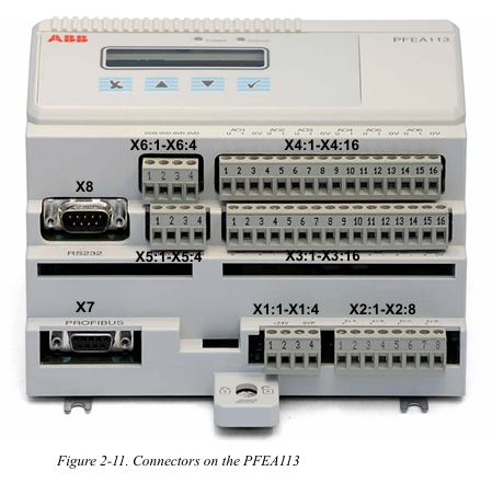
Core components: Tension electronic unit (PFEA113), weighing sensors (such as PFCL/PFTL series), junction box (PFXC 141), power module, and communication interface.
Measurement principle: Based on the magnetostriction effect, the sensor core is a stacked alloy sheet. A 330Hz AC current is passed through the primary winding to generate a magnetic field. The secondary winding induces a voltage signal proportional to the tension due to mechanical force, and has strong resistance to lateral and axial force interference (error ≤± 0.5%).
2. Core Features
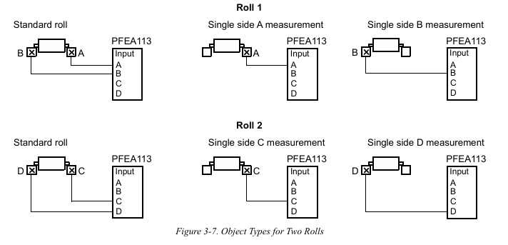
Multi scenario adaptation: Supports single roll, double roll, and segmented roll applications, and can connect up to 12 sensors (cascaded through 3 PFEA113).
Flexible expansion: 6 configurable analog outputs, 4 digital outputs, supports Profibus DP communication, compatible with remote control and data upload.
High reliability: It has protection functions such as overvoltage (OVP), overcurrent (OCP), and over temperature (OTP), and supports fault self diagnosis.
Installation and wiring specifications
1. Installation environment requirements
Physical environment: Operating temperature -10~+55 ℃ (IP20 version), -25~+70 ℃ (IP65 version), relative humidity ≤ 95% (no condensation), avoid strong electromagnetic interference sources (such as frequency converters).
Mechanical requirements: The flatness error of the installation surface should be ≤ 0.1mm, and the gap between the sensor and the adapter plate should be clean and free of debris to avoid force diversion affecting measurement accuracy.
2. Hardware wiring
Sensor wiring:
Analog input supports CT (1A/5A), VT (100V), and sensor signals, and the cable needs to be twisted shielded with a single end grounding of the shielding layer.
Switching input/output adopts optocoupler isolation, with digital output capacity 5A@250V AC/DC, Inductive loads require parallel freewheeling diodes.
Power and Communication:
Wide range auxiliary power supply (24-250V AC/DC, IP20 version) or 85-264V AC (IP65 version), power consumption<15W.
The communication interface supports Profibus DP (RS485) and RS232, with a standard 120 Ω terminal resistor and a maximum communication distance of 1200m.
Debugging and configuration process
1. Basic settings
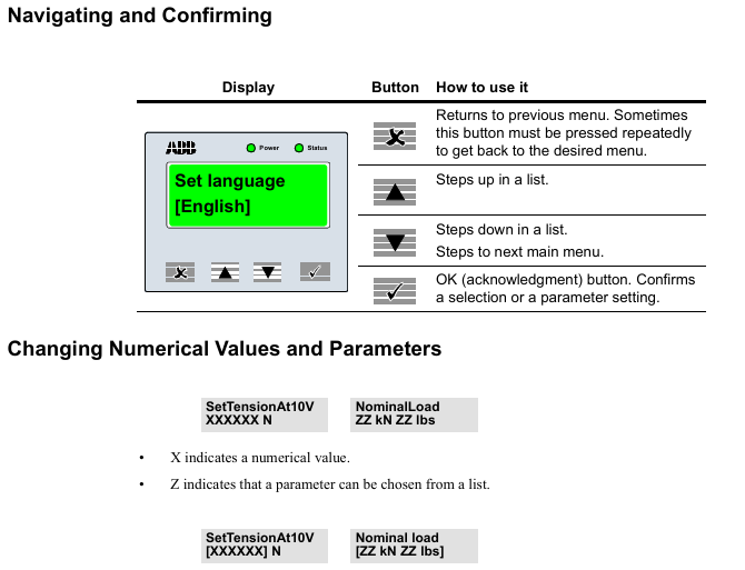
Quick configuration: Set language (English/German/French, etc.), unit (N/kN/kg, etc.), and web width (applicable to N/m, etc.) through panel buttons, supporting fast zero calibration and gain scheduling.
Complete configuration: including system definition (single roll/double roll/segmented roll), sensor type selection, nominal load setting, zero calibration, and wrrap gain calculation (calculated by hanging weight or formula).
2. Key parameter configuration
Wrap gain: the ratio of tension (T) to sensor measured force (FR), calculated as Wrap gain=T/FR, which needs to be derived through geometric relationships based on the installation angle (horizontal/inclined).
Communication settings: Profibus DP address (0-125), baud rate (up to 12Mbps), supports real-time data exchange with PLC or SCADA systems.
Operation and maintenance
Daily operating procedures
1. Startup and shutdown
(1) Startup steps
Pre inspection
Confirm that the main power supply voltage matches the rated value of the equipment (IP20 version: 24V DC; IP65 version: 85-264V AC).
Check that the sensors, junction boxes, and communication cables are securely connected without looseness or damage.
Power on operation
Turn on the external power switch, and the IP65 version requires the internal switch of the device to be turned on at the same time.
The "Power" indicator light (green) on the observation panel is on, and the "Status" indicator light (green) is constantly on, indicating that the system is normal; If the "Status" light is red, the fault information needs to be viewed through the display screen.
(2) Shutdown steps
Turn off the external power switch. For IP65 version, the internal switch of the device needs to be turned off first.
When the machine is shut down for a long time, it is recommended to disconnect the main power supply and protect the equipment from dust.
2. Operation monitoring
(1) Panel operation
Display switching: Use the "Step up/down" button to switch display content, including single sensor tension (such as Tension A), total tension (such as TensionRoll 1), differential tension (such as TensionDiff A-B), and analog output values (AO1-AO6).
Parameter viewing: Press and hold the "OK" button for 5 seconds to enter the menu, where you can browse the system status, fault records, and configuration parameters (such as w_rap gain _, nominal load).
(2) Remote monitoring
Through Profibus DP communication, the upper computer (such as PLC) can read tension values, sensor status, and alarm information in real time, and support remote sending of zero calibration, gain switching, and other instructions.
3. Key operational functions
(1) Zero point calibration
Trigger condition: When no tension is applied (such as when the coil is not running), execute it through the "Zero Set" menu on the panel or remote command.
Operation steps:
Enter the "ZeroSet" menu and select the corresponding sensor group (such as A, B).
After confirming that there is no tension, press "OK" and the display screen will show "ActionDone" to indicate completion.
(2) Gain scheduling
Application scenario: Suitable for changes in coil path (such as different wrrap angles), switching preset wrrap gain parameters through digital input or Profibus.
Setting method: Enable "GainScheduling" in the "SystemDefinition" menu, and configure the w_rap gain 1_ and w_rap gain 2h respectively.
Maintenance and upkeep
1. Preventive maintenance
(1) Regular check (recommended every 6 months)
Key operating points for inspection items
Check the torque of the fixing screws for sensors and connectors (e.g. 24Nm for M12 screws), and clean the dust or debris in the gap between the sensor and adapter board.
Confirm that the cable and shielding layer are not worn, and that the shielding layer is grounded at one end (distance ≤ 50mm) to avoid interference caused by grounding at both ends.
Ventilation openings for heat dissipation and environmental cleaning equipment ensure that the working environment temperature and humidity are within the rated range (without condensation or corrosive gases).
(2) Calibration and verification
Calibration cycle: It is recommended to perform accuracy calibration once a year, using standard weight or calibration equipment to verify measurement errors (should be ≤ ± 0.5% FS).
Verification method: Enter a known tension value through the simulation function in "DataMenu", and compare the displayed value with the theoretical value.

- OMRON
- ABB
- General Electric
- EMERSON
- Honeywell
- HIMA
- ALSTOM
- Rolls-Royce
- MOTOROLA
- Rockwell
- Siemens
- Woodward
- YOKOGAWA
- FOXBORO
- KOLLMORGEN
- MOOG
- KB
- YAMAHA
- BENDER
- TEKTRONIX
- Westinghouse
- AMAT
- AB
- XYCOM
- Yaskawa
- B&R
- Schneider
- KONGSBERG
- NI
- WATLOW
- ProSoft
- SEW
- ADVANCED
- Reliance
- TRICONEX
- METSO
- MAN
- Advantest
- STUDER
- DANAHER MOTION
- Bently
- Galil
- EATON
- MOLEX
- DEIF
- B&W
- ZYGO
- Aerotech
- DANFOSS
- Beijer
- Moxa
- Rexroth
- Johnson
- WAGO
- TOSHIBA
- BMCM
- SMC
- HITACHI
- HIRSCHMANN
- Application field
- XP POWER
- CTI
- TRICON
- STOBER
- Thinklogical
- Horner Automation
- Meggitt
- Fanuc
- Baldor
- SHINKAWA
- Other Brands
- UniOP
- KUKA
- Iba
- Beckhoff
-
 Basler DECS-200-2L Digital Excitation Control
 -
 Basler BE1-47N Voltage Phase Sequence Relay
 -
 Basler AEC63-7 Analog Excitation Controller 220-277V
 -
 Basler BE1-50/51B-107 Overcurrent Relay
 -
 Basler Electric BE1‑32R BE1‑E1P‑BON0F Protective Relay
 -
 Basler BE1-25 Solid State Time Overcurrent Relay M1EA6PA5S1F
 -
 Basler MVC 232 Manual Voltage Control Module 90 37000 103 60VAC 55VDC
 -
 Basler RAL6144-16GM Racer GigE Line Scan Camera
 -
 Basler SSR 63-12 Static Voltage Regulator
 -
 Basler BE1-51A Overcurrent Relay
 -
 Basler BE1-87T Solid State Protective Relay
 -
 Basler SR4A2B01B3A Static Voltage Regulator
 -
 Basler SSR 32-12 Static Voltage Regulator
 -
 Basler TRR00696 Transformer 1KVA 115V
 -
 Basler DECS-100-B15 AVR Replacement
 -
Basler BE1-27 Under-Voltage Relay
-
 Basler ACA2000-50GM Interface Module
 -
 Basler AEC63-7 Analog Excitation Controller
 -
 Basler PRS 250 Veri-Sync Relay
 -
 Basler SR4A-2B15B3A Static Voltage Regulator
 -
Basler BE1-32R Power Relay
-
Basler SR8A-2B06B3E Static Voltage Regulator
-
Basler BE1-81 O/U Frequency Relay
-
 Basler BE1-51A-K2E-W6M-B1N0F Overcurrent Relay
 -
Basler BE1-851 Overcurrent Relay G3A1S1 – 48-125V AC/DC
-
 Basler BEI-51 Overcurrent Relay – NSN 5945-01-293-2363
 -
Basler Electric L301KC Protective Relay – L301KC
-
 Basler DECS-100-B15 Automatic Voltage Regulator – Generator AVR
 -
 Basler SR4A-2B15B3A Static Voltage Regulator – SR4A2B15B3A
 -
 Basler UF 312 Under Frequency Protective Module – 9094700100
 -
Basler Electric MVC 232 Manual Control Module – 60VAC 55VDC 20A
-
Basler PRS 250 Veri-Sync Relay – Generator Synchronizing Relay
-
 Basler DECS-100-A05 Digital Regulator Review
 -
 Basler AEM-2020 Analog Expansion Module Specs
 -
 Basler DECS-100-B15 Digital Excitation Specs
 -
Basler Electric 9125600106 Regulator Component
-
Basler BE1-51A-K1E-W6M-B1N0F Overcurrent Relay
-
 Basler MVC-301 MVC 300 Excitation Controller
 -
 Basler SSR 32-12 Static Voltage Regulator
 -
 Basler 9-2849-00-101 Control Module
 -
Basler BE1-51A Overcurrent Relay
-
 Basler BE1-51/27R Overcurrent Relay
 -
 Basler BE1-51 Overcurrent Relay
 -
 Basler SR8A-2B15B3A Static Voltage Regulator
 -
 Basler BE32965001 Transformer and Timer Board
 -
 Basler 9174700100 EL200-7 Excitation Limiter
 -
 Basler BE2000E AVR Voltage Regulator
 -
Basler BE1-87G Differential Relay
-
 Basler BE21834001 Generator Control Module
 -
Basler DECS-100-B15 AVR
-
 Basler D90 96801 100 PCB Card
 -
 Basler XR2002F Voltage Regulator (110 VAC, 48-480 Hz)
 -
 Basler SR8A-2B14B3A Regulator
 -
 Basler 9561500100 Module
 -
 Basler DECS-400 BE1-11 System
 -
 Basler DECS-100-B15 Excitation Control
 -
 Basler SCP 210 Frequency Controller
 -
Basler SR4A-2B15B3A Static Voltage Regulator
-
Basler BE1-32R Power Relay
-
 Basler PIA2400-17GM Power Interface Adapter
 -
 Basler MVC 232 Manual Voltage Control Module
 -
 Basler SSR 32-12 Static Voltage Regulator
 -
Basler 5MW AVR Generator Voltage Regulator
-
 Basler VR63-4B Voltage Regulator
 -
Basler DECS-100-A05 AVR for Engine Generator
-
Basler DECS-100-B15 Automatic Voltage Regulator
-
Basler BE1-32R Directional Power Relay
-
Basler BE1-87B Differential Relay
-
 Basler UFOV 260A Protective Module
 -
 Basler 9-2614-02-100 PCB Rev M
 -
Basler DECS-100-B15 Digital AVR
-
 Basler 9284900103 PS DECS-400N
 -
 Basler D4N3H1U Intertie Protection
 -
 Basler DECS-100-B15 A15 AVR
 -
 Basler KR4F Voltage Regulator
 -
 Basler BE26434 T14 Transformer
 -
 Basler SR8A-2B15B3A Regulator
 -
 Westinghouse 774B472A12 AR Relay
 -
Basler DECS-100-B15 AVR
-
Basler XR2002F Regulator 110V
-
Basler SR125-E Static Regulator
-
Basler SSR 125-12 Regulator
-
Basler MOC2599 Motor Pot
-
 Basler BE1-DFPR Feeder Relay
 -
 Basler CBS 305 Current Boost
 -
Basler BE1-25 AutoSync
-
Basler MVC 300 Voltage Control
-
 Basler BE3-25A AutoSync
 -
 Basler KR7FF Static Regulator
 -
Basler 90-49000-100 Regulator
-
 Basler 880 kVA Dry Type Transformer Specs
 -
Basler Electric BE1-25 Sync-Check Relay Specs
-
 Basler SSR 125-12 Voltage Regulator Specs
 -
 Basler Electric BE1-851 Overcurrent Relay Review
 -
Basler Electric 149D930G02 Control Sub-Assembly
-
 Basler Electric BE1-81O/UT Frequency Relay Specs
 -
 Basler Electric BE1-51/27C Overcurrent Relay
 -
 Basler Electric 149D956G02 Industrial Component
 -
Basler Electric BE1-51A Overcurrent Relay Specs
-
 Basler Electric BE1-40Q Loss of Excitation Relay
 -
Basler DECS-200 Excitation Control System
-
 Basler DECS-200 Voltage Regulator 56-277V AC / 125V DC
 -
Basler BE1-87T Transformer Differential Relay
-
 Basler RDP-110-S1 Protection Relay
 -
 Basler BE1-700V Digital Protective Relay
 -
 Basler BE1-951 Overcurrent Protection System
 -
 Basler DECS-300 Digital Excitation Control
 -
 Basler DECS-200 Digital Excitation Control
 -
 Basler DECS-200-1C Excitation Control System
 -
Basler DECS-200-1L Digital Excitation Control
-
 Basler Electric BE1-GPS Generator Protection System
 -
Basler Electric DECS-200-1C Digital Excitation Controller
-
 Basler Electric DECS125-15 Excitation Control with Power Module
 -
Basler Electric BE1-87G Differential Relay
-
 Basler Electric BE1-11 Protection System I5A3M2P2N0EA00
 -
Basler Electric DECS-200-1C Excitation Control System
-
Basler Electric BE1-11g Generator Protection Relay
-
Basler Electric DECS 125-15-B2C1 V2.0.9 Excitation Control
-
Basler Electric BE1-81O/UT3ED1JA7N2F Frequency Relay
-
Basler Electric BE1-81O/UT3EE1YB7N1F Frequency Relay
-
 Basler Electric DECS-200-1L Digital Excitation Control System
 -
Basler DECS125-15-B2C1 Excitation Control
-
 Basler 9507900205 SSR Retrofit Voltage Regulator
 -
 Basler BE2000E Digital Voltage Regulator
 -
 Basler BE1-GPS Generator Protection System
 -
Basler DECS-250-CN1CN1N Digital Excitation Control
-
 Basler DGC-2020 Genset Controller
 -
Basler BE1-81O UT3ED1LA7N0F Frequency Relay (Variant)


