ABB PFEA113 Tension Electronic Equipment
ABB PFEA113 Tension Electronic Equipment
Product positioning
PFEA113 is based on Presductor ® The high-precision tension measurement and control system of technology is used for tension detection and control in the production process of coil materials such as paper, metal strips, and plastic films. It supports multiple types of weighing sensors (PFCL 301E, PFTL 301E, etc.) and is widely used in industries such as papermaking, printing, and metallurgy.

System composition and core technology
1. System composition
Core components: Tension electronic unit (PFEA113), weighing sensors (such as PFCL/PFTL series), junction box (PFXC 141), power module, and communication interface.
Measurement principle: Based on the magnetostriction effect, the sensor core is a stacked alloy sheet. A 330Hz AC current is passed through the primary winding to generate a magnetic field. The secondary winding induces a voltage signal proportional to the tension due to mechanical force, and has strong resistance to lateral and axial force interference (error ≤± 0.5%).
2. Core Features
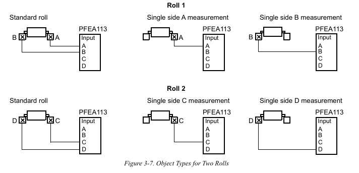
Multi scenario adaptation: Supports single roll, double roll, and segmented roll applications, and can connect up to 12 sensors (cascaded through 3 PFEA113).
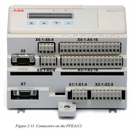
Flexible expansion: 6 configurable analog outputs, 4 digital outputs, supports Profibus DP communication, compatible with remote control and data upload.
High reliability: It has protection functions such as overvoltage (OVP), overcurrent (OCP), and over temperature (OTP), and supports fault self diagnosis.
Installation and wiring specifications
1. Installation environment requirements
Physical environment: Operating temperature -10~+55 ℃ (IP20 version), -25~+70 ℃ (IP65 version), relative humidity ≤ 95% (no condensation), avoid strong electromagnetic interference sources (such as frequency converters).
Mechanical requirements: The flatness error of the installation surface should be ≤ 0.1mm, and the gap between the sensor and the adapter plate should be clean and free of debris to avoid force diversion affecting measurement accuracy.
2. Hardware wiring
Sensor wiring:
Analog input supports CT (1A/5A), VT (100V), and sensor signals, and the cable needs to be twisted shielded with a single end grounding of the shielding layer.
Switching input/output adopts optocoupler isolation, with digital output capacity 5A@250V AC/DC, Inductive loads require parallel freewheeling diodes.
Power and Communication:
Wide range auxiliary power supply (24-250V AC/DC, IP20 version) or 85-264V AC (IP65 version), power consumption<15W.
The communication interface supports Profibus DP (RS485) and RS232, with a standard 120 Ω terminal resistor and a maximum communication distance of 1200m.

Debugging and configuration process
1. Basic settings
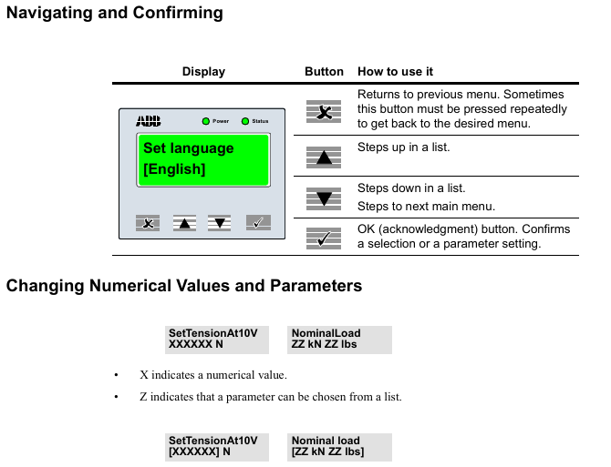
Quick configuration: Set language (English/German/French, etc.), unit (N/kN/kg, etc.), and web width (applicable to N/m, etc.) through panel buttons, supporting fast zero calibration and gain scheduling.
Complete configuration: including system definition (single roll/double roll/segmented roll), sensor type selection, nominal load setting, zero calibration, and wrrap gain calculation (calculated by hanging weight or formula).
2. Key parameter configuration
Wrap gain: the ratio of tension (T) to sensor measured force (FR), calculated as Wrap gain=T/FR, which needs to be derived through geometric relationships based on the installation angle (horizontal/inclined).
Communication settings: Profibus DP address (0-125), baud rate (up to 12Mbps), supports real-time data exchange with PLC or SCADA systems.
Operation and maintenance
Daily operating procedures
1. Startup and shutdown
(1) Startup steps
Pre inspection
Confirm that the main power supply voltage matches the rated value of the equipment (IP20 version: 24V DC; IP65 version: 85-264V AC).
Check that the sensors, junction boxes, and communication cables are securely connected without looseness or damage.
Power on operation
Turn on the external power switch, and the IP65 version requires the internal switch of the device to be turned on at the same time.
The "Power" indicator light (green) on the observation panel is on, and the "Status" indicator light (green) is constantly on, indicating that the system is normal; If the "Status" light is red, the fault information needs to be viewed through the display screen.
(2) Shutdown steps
Turn off the external power switch. For IP65 version, the internal switch of the device needs to be turned off first.
When the machine is shut down for a long time, it is recommended to disconnect the main power supply and protect the equipment from dust.

2. Operation monitoring
(1) Panel operation
Display switching: Use the "Step up/down" button to switch display content, including single sensor tension (such as Tension A), total tension (such as TensionRoll 1), differential tension (such as TensionDiff A-B), and analog output values (AO1-AO6).
Parameter viewing: Press and hold the "OK" button for 5 seconds to enter the menu, where you can browse the system status, fault records, and configuration parameters (such as w_rap gain _, nominal load).
- ABB
- General Electric
- EMERSON
- Honeywell
- HIMA
- ALSTOM
- Rolls-Royce
- MOTOROLA
- Rockwell
- Siemens
- Woodward
- YOKOGAWA
- FOXBORO
- KOLLMORGEN
- MOOG
- KB
- YAMAHA
- BENDER
- TEKTRONIX
- Westinghouse
- AMAT
- AB
- XYCOM
- Yaskawa
- B&R
- Schneider
- Kongsberg
- NI
- WATLOW
- ProSoft
- SEW
- ADVANCED
- Reliance
- TRICONEX
- METSO
- MAN
- Advantest
- STUDER
- KONGSBERG
- DANAHER MOTION
- Bently
- Galil
- EATON
- MOLEX
- DEIF
- B&W
- ZYGO
- Aerotech
- DANFOSS
- Beijer
- Moxa
- Rexroth
- Johnson
- WAGO
- TOSHIBA
- BMCM
- SMC
- HITACHI
- HIRSCHMANN
- Application field
- XP POWER
- CTI
- TRICON
- STOBER
- Thinklogical
- Horner Automation
- Meggitt
- Fanuc
- Baldor
- SHINKAWA
- Other Brands


